Electrode For Electrolysis
MIYASAKA; Toyomitsu ; et al.
U.S. patent application number 16/462367 was filed with the patent office on 2019-11-07 for electrode for electrolysis. This patent application is currently assigned to ASAHI KASEI KABUSHIKI KAISHA. The applicant listed for this patent is ASAHI KASEI KABUSHIKI KAISHA. Invention is credited to Yoshifumi KADO, Toyomitsu MIYASAKA, Makoto NISHIZAWA.
| Application Number | 20190338429 16/462367 |
| Document ID | / |
| Family ID | 62195992 |
| Filed Date | 2019-11-07 |


| United States Patent Application | 20190338429 |
| Kind Code | A1 |
| MIYASAKA; Toyomitsu ; et al. | November 7, 2019 |
ELECTRODE FOR ELECTROLYSIS
Abstract
An electrode for electrolysis according to the present invention is an electrode for electrolysis including a conductive substrate; and a catalyst layer formed on a surface of the conductive substrate, wherein the catalyst layer comprises ruthenium element, iridium element, titanium element, and at least one first transition metal element selected from the group consisting of Sc, V, Cr, Fe, Co, Ni, Cu, and Zn, a content ratio of the first transition metal element contained in the catalyst layer based on 1 mol of the titanium element is 0.25 mol % or more and less than 3.4 mol %, and a D value being an indicator of an electric double layer capacitance of the electrode for electrolysis is 120 C/m.sup.2 or more and 420 C/m.sup.2 or less.
| Inventors: | MIYASAKA; Toyomitsu; (Tokyo, JP) ; NISHIZAWA; Makoto; (Tokyo, JP) ; KADO; Yoshifumi; (Tokyo, JP) | ||||||||||
| Applicant: |
|
||||||||||
|---|---|---|---|---|---|---|---|---|---|---|---|
| Assignee: | ASAHI KASEI KABUSHIKI
KAISHA Tokyo JP |
||||||||||
| Family ID: | 62195992 | ||||||||||
| Appl. No.: | 16/462367 | ||||||||||
| Filed: | November 17, 2017 | ||||||||||
| PCT Filed: | November 17, 2017 | ||||||||||
| PCT NO: | PCT/JP2017/041559 | ||||||||||
| 371 Date: | May 20, 2019 |
| Current U.S. Class: | 1/1 |
| Current CPC Class: | C25B 9/00 20130101; C25B 11/0415 20130101; C25B 11/0494 20130101; C25B 1/46 20130101; C25B 9/10 20130101; C25B 11/0484 20130101 |
| International Class: | C25B 11/04 20060101 C25B011/04; C25B 9/10 20060101 C25B009/10 |
Foreign Application Data
| Date | Code | Application Number |
|---|---|---|
| Nov 22, 2016 | JP | 2016-227066 |
Claims
1. An electrode for electrolysis comprising: a conductive substrate; and a catalyst layer formed on a surface of the conductive substrate, wherein the catalyst layer comprises ruthenium element, iridium element, titanium element, and at least one first transition metal element selected from the group consisting of Sc, V, Cr, Fe, Co, Ni, Cu, and Zn, a content ratio of the first transition metal element contained in the catalyst layer based on 1 mol of the titanium element is 0.25 mol % or more and less than 3.4 mol %, and a D value being an indicator of an electric double layer capacitance of the electrode for electrolysis is 120 C/m.sup.2 or more and 420 C/m.sup.2 or less.
2. The electrode for electrolysis according to claim 1, wherein the first transition metal element forms a solid solution with a solid solution of a ruthenium oxide, an iridium oxide, and a titanium oxide.
3. The electrode for electrolysis according to claim 1, wherein the first transition metal element comprises at least one metal element selected from the group consisting of vanadium, cobalt, copper, and zinc.
4. The electrode for electrolysis according to claim 1, wherein the first transition metal element comprises vanadium element.
5. The electrode for electrolysis according to claim 1, wherein a content ratio of the first transition metal element based on all metal elements contained in the catalyst layer is 10 mol % or more and 30 mol % or less.
6. The electrode for electrolysis according to claim 1, wherein a content ratio of the first transition metal element contained in the catalyst layer based on 1 mol of the ruthenium element is 0.3 mol or more and less than 2 mol.
7. The electrode for electrolysis according to claim 1, wherein the D value is 120 C/m.sup.2 or more and 380 C/m.sup.2 or less.
8. A method for producing the electrode for electrolysis according to claim 1, comprising: preparing a coating liquid comprising a ruthenium compound, an iridium compound, a titanium compound and a compound comprising the first transition metal element; coating at least one surface of the conductive substrate with the coating liquid to form a coating film; and calcining the coating film under an oxygen-containing atmosphere to form the catalyst layer.
9. An electrolyzer comprising the electrode for electrolysis according to claim 1.
Description
TECHNICAL FIELD
[0001] The present invention relates to an electrode for electrolysis and a method for producing the same, and an electrolyzer comprising the electrode for electrolysis.
BACKGROUND ART
[0002] Sodium chloride electrolysis by ion exchange membrane process is a method for electrolyzing brine using electrode for electrolysis to thereby produce caustic soda, chlorine, and hydrogen. For the process of sodium chloride electrolysis by ion exchange membrane process, a technique that can maintain low electrolysis voltage over a long period of time is required for power consumption reduction.
[0003] When the breakdown of electrolysis voltage is analyzed in detail, it becomes clear that in addition to theoretically necessary electrolysis voltage, voltage resulting from the resistance of the ion exchange membrane and the structural resistance of the electrolyzer, the overvoltage of the anode and the cathode, which are electrodes for electrolysis, voltage resulting from the distance between the anode and the cathode, and the like are included. In addition, when electrolysis is continued over a long period of time, voltage increase and the like induced by various causes such as impurities in brine may occur.
[0004] Among the various electrolysis voltages described above, studies have been conducted for the purpose of reducing the overvoltage of the chlorine generating anode. For example, Patent Literature 1 discloses the technique of an insoluble anode obtained by coating a titanium substrate with an oxide of a platinum group metal such as ruthenium. This anode is referred to as DSA (registered trademark, Dimension Stable Anode). In addition, Non Patent Literature 1 describes the historical developments in soda electrolysis techniques using DSA.
[0005] Regarding the above-described DSA, also until now, various improvements have been made and studies for performance improvement have been conducted.
[0006] For example, Patent Literature 2 reports a chlorine generating electrode obtained by alloying platinum and palladium, paying attention to the low chlorine overvoltage and high oxygen overvoltage of palladium in the platinum group. Patent Literature 3 and Patent Literature 4 propose an electrode obtained by subjecting the surface of a platinum-palladium alloy to oxidation treatment to form palladium oxide on the surface. In addition, Patent Literature 5 proposes an electrode coated with an external catalyst layer containing an tin oxide as the main component and containing oxides of ruthenium, iridium, palladium, and niobium. With this electrode, an attempt is made to suppress an oxygen generation reaction in the anode occurring simultaneously with chlorine generation, in order to obtain high purity chlorine having a low oxygen concentration.
CITATION LIST
Patent Literature
[0007] Patent Literature 1: Japanese Patent Publication No. 46-021884 [0008] Patent Literature 2: Japanese Patent Publication No. 45-11014 [0009] Patent Literature 3: Japanese Patent Publication No. 45-11015 [0010] Patent Literature 4: Japanese Patent Publication No. 48-3954 [0011] Patent Literature 5: National Publication of International Patent Application No. 2012-508326
Non Patent Literature
[0011] [0012] Non Patent Literature 1: Hiroaki Aikawa, "National Museum of Nature and Science, Survey Reports on the Systemization of Technologies No. 8", published by Independent Administrative Institution National Museum of Nature and Science, Mar. 30, 2007, p 32
SUMMARY OF INVENTION
Technical Problem
[0013] However, a problem of the conventional anodes such as DSA described in Patent Literature 1 is that the overvoltage immediately after the start of electrolysis becomes high, and a certain period is required before stabilization at low overvoltage due to the activation of the catalyst, and therefore power consumption loss occurs during electrolysis.
[0014] In addition, the chlorine generating electrodes described in Patent Literatures 2 to 4 may have high overvoltage and low durability. Further, in the production of the electrodes described in Patent Literatures 3 and 4, it is necessary to use an alloy for the substrate itself, and in addition, a complicated step is required, such as forming an oxide on the substrate by thermal decomposition followed by alloying by reduction and further the formation of palladium oxide by electrolytic oxidation; great improvement is thus needed both practically and in terms of the production method.
[0015] The electrode described in Patent Literature 5 has a certain effect on improvement in the electrolysis duration (electrode life) of palladium (Note: palladium is considered to be poor in chemical resistance), but cannot be said to sufficiently lower the chlorine generating overvoltage.
[0016] As described above, the techniques described in Patent Literatures 1 to 5 and Non Patent Literature 1 cannot provide an electrode for electrolysis that has sufficiently low overvoltage at the initial stage of electrolysis and allows electrolysis to be carried out at low voltage and low power consumption over a long period of time.
[0017] The present invention has been made in order to solve the above-described problems. Therefore, an object of the present invention is to provide an electrode for electrolysis that can reduce overvoltage at the initial stage of electrolysis and allows electrolysis to be carried out at low voltage and low power consumption over a long period of time, and a method for producing the same, and an electrolyzer comprising the electrode for electrolysis.
Solution to Problem
[0018] The present inventors have studied diligently in order to solve the above problems. As a result, the present inventors have found that by adjusting, in a particular range, a numerical value that is an indicator of the electric double layer capacitance of an electrode for electrolysis having a catalyst layer containing predetermined metal elements at a predetermined ratio, the overvoltage at the initial stage of electrolysis can be reduced, and electrolysis can be carried out at low voltage and low power consumption over a long period of time, thereby completing the present invention.
[0019] Specifically, the present invention is as follows.
[1]
[0020] An electrode for electrolysis comprising:
[0021] a conductive substrate; and
[0022] a catalyst layer formed on a surface of the conductive substrate, wherein
[0023] the catalyst layer comprises ruthenium element, iridium element, titanium element, and at least one first transition metal element selected from the group consisting of Sc, V, Cr, Fe, Co, Ni, Cu, and Zn,
[0024] a content ratio of the first transition metal element contained in the catalyst layer based on 1 mol of the titanium element is 0.25 mol % or more and less than 3.4 mol %, and
[0025] a D value being an indicator of an electric double layer capacitance of the electrode for electrolysis is 120 C/m.sup.2 or more and 420 C/m.sup.2 or less.
[2]
[0026] The electrode for electrolysis according to [1], wherein the first transition metal element forms a solid solution with a solid solution of a ruthenium oxide, an iridium oxide, and a titanium oxide.
[3]
[0027] The electrode for electrolysis according to [1] or [2], wherein the first transition metal element comprises at least one metal element selected from the group consisting of vanadium, cobalt, copper, and zinc.
[4]
[0028] The electrode for electrolysis according to any of [1] to [3], wherein the first transition metal element comprises vanadium element.
[5]
[0029] The electrode for electrolysis according to any of [1] to [4], wherein a content ratio of the first transition metal element based on all metal elements contained in the catalyst layer is 10 mol % or more and 30 mol % or less.
[6]
[0030] The electrode for electrolysis according to any of [1] to [5], wherein a content ratio of the first transition metal element contained in the catalyst layer based on 1 mol of the ruthenium element is 0.3 mol or more and less than 2 mol.
[7]
[0031] The electrode for electrolysis according to any of [1] to [6], wherein the D value is 120 C/m.sup.2 or more and 380 C/m.sup.2 or less.
[8]
[0032] A method for producing the electrode for electrolysis according to any of [1] to [7], comprising the steps of:
[0033] preparing a coating liquid comprising a ruthenium compound, an iridium compound, a titanium compound and a compound comprising the first transition metal element;
[0034] coating at least one surface of the conductive substrate with the coating liquid to form a coating film; and
[0035] calcining the coating film under an oxygen-containing atmosphere to form the catalyst layer.
[9]
[0036] An electrolyzer comprising the electrode for electrolysis according to any of [1] to [7].
Advantageous Effects of Invention
[0037] The present invention provides an electrode for electrolysis that can reduce overvoltage at the initial stage of electrolysis and allows electrolysis to be carried out at low voltage and low power consumption over a long period of time.
BRIEF DESCRIPTION OF DRAWINGS
[0038] FIG. 1 illustrates a cross-sectional schematic view according to one example of an electrolyzer of the present embodiment.
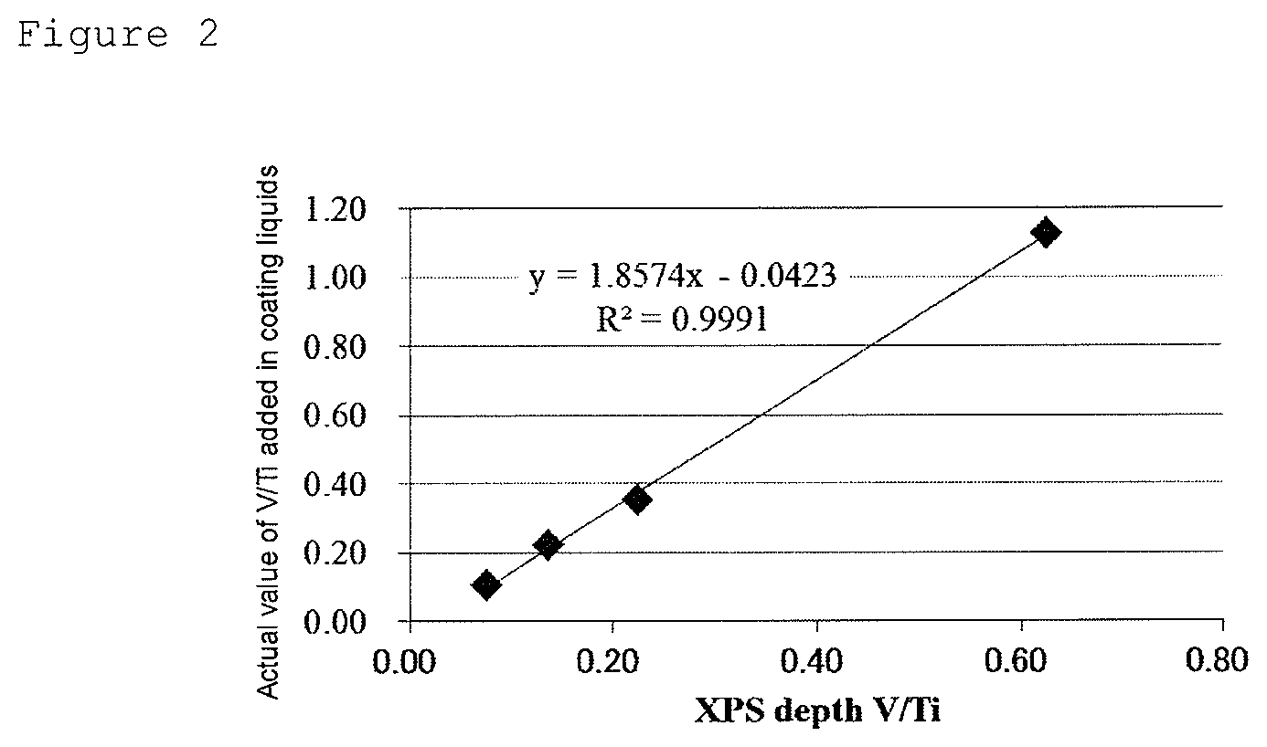
[0039] FIG. 2 illustrates a graph showing the results of plotting and linearly approximating the measured values of V/Ti obtained by XPS depth profile analysis and actual values of V/Ti added in coating liquids, for four samples having different element ratios (molar ratios) between V and Ti.
DESCRIPTION OF EMBODIMENTS
[0040] An embodiment for carrying out the present invention (hereinafter simply referred to as "present embodiment") will be described in detail below. The present embodiment below is an illustration for describing the present invention and is not intended to limit the present invention to the following contents. Appropriate modifications can be made to the present invention without departing from the spirit thereof.
[0041] An electrode for electrolysis of the present embodiment is an electrode for electrolysis comprising a conductive substrate; and a catalyst layer formed on a surface of the conductive substrate, wherein the catalyst layer comprises ruthenium element, iridium element, titanium element, and at least one first transition metal element selected from the group consisting of scandium, vanadium, chromium, iron, cobalt, nickel, copper, and zinc (these transition metal elements are hereinafter also collectively referred to as "first transition metal elements"). Further, the electrode for electrolysis of the present embodiment is configured such that the content ratio of the first transition metal element contained in the catalyst layer based on 1 mol of the titanium element is 0.25 mol % or more and less than 3.4 mol %, and the D value being an indicator of the electric double layer capacitance of the electrode for electrolysis is 120 C/m.sup.2 or more and 420 C/m.sup.2 or less.
[0042] In the present embodiment, using the first transition metal element in addition to the ruthenium element, the iridium element, and the titanium element in the catalyst layer provides an electrode for electrolysis in which the peak position of the peak attributed to Ru 3d5/2 derived from RuO.sub.2, measured by X-ray photoelectron spectroscopy (XPS), shifts from 280.5 eV for RuO.sub.2 to the high binding energy side. For charging correction in XPS, correction is performed so that the binding energy of Ti 2p3/2 is 458.4 eV. The shift of the peak position of Ru 3d5/2 to the high binding energy side indicates a state in which Ru is more oxidized in terms of the charge, and this is considered to be due to the addition of the first transition metal element. For example, when vanadium is added as the first transition metal element, the following polarization occurs.
RuO.sub.2+VO.sub.2->RuO.sub.2.sup..delta.++VO.sub.2.sup..delta.-
[0043] RuO.sub.2.sup..delta.+ is an active adsorption site for adsorbing chlorine and promotes chlorine adsorption, and thus chlorine generating overvoltage can be reduced.
[0044] Although limitation to the above-described mechanism of action is not intended, the electrode for electrolysis of the present embodiment has the above-described configuration, and therefore when electrolysis is performed using the electrode for electrolysis, the overvoltage at the initial stage of the electrolysis can be reduced and the electrolysis can be performed at low voltage and low power consumption over a long period of time. The electrode for electrolysis of the present embodiment can be preferably used as a chlorine generating electrode particularly for sodium chloride electrolysis by ion exchange membrane process.
(Conductive Substrate)
[0045] The electrode for electrolysis of the present embodiment may be used in brine of a high concentration close to saturation in a chlorine gas generating atmosphere. Therefore, as the material of the conductive substrate in the present embodiment, corrosion-resistant valve metals are preferred. Examples of the valve metals include, but are not limited to, titanium, tantalum, niobium, and zirconium. From the viewpoint of economy and affinity for the catalyst layer, titanium is preferred.
[0046] The shape of the conductive substrate is not particularly limited, and a suitable shape can be selected according to the purpose. For example, shapes such as an expanded shape, a porous plate shape, and a wire mesh shape are preferably used. The thickness of the conductive substrate is preferably 0.1 to 2 mm.
[0047] The surface of the conductive substrate to be in contact with the catalyst layer is preferably subjected to surface area increasing treatment in order to improve adhesiveness to the catalyst layer. Examples of the method of surface area increasing treatment include, but are not limited to, blasting treatment using cut wires, a steel grid, an alumina grid, or the like; and acid treatment using sulfuric acid or hydrochloric acid. Of these treatments, a method of forming irregularities on the surface of the conductive substrate by blasting treatment and then further performing acid treatment is preferred.
(Catalyst Layer)
[0048] The catalyst layer to be formed on the surface of the conductive substrate subjected to the above-described treatment comprises ruthenium element, iridium element, titanium element, and a first transition metal element.
[0049] The ruthenium element, the iridium element, and the titanium element are each preferably in the form of an oxide.
[0050] Examples of the ruthenium oxide include, but are not limited to, RuO.sub.2.
[0051] Examples of the iridium oxide include, but are not limited to, IrO.sub.2.
[0052] Examples of the titanium oxide include, but are not limited to, TiO.sub.2.
[0053] In the catalyst layer in the present embodiment, the ruthenium oxide, the iridium oxide, and the titanium oxide preferably form a solid solution. When the ruthenium oxide, the iridium oxide, and the titanium oxide form a solid solution, the durability of the ruthenium oxide improves further.
[0054] A solid solution generally refers to a material in which two or more types of substances dissolve in each other, and the whole is a uniform solid phase. Examples of the substances forming the solid solution include metal simple substances and metal oxides. Particularly in the case of a solid solution of metal oxides preferred for the present embodiment, two or more types of metal atoms are irregularly arranged on equivalent lattice points in a unit lattice in the oxide crystal structure. Specifically, a substitutional solid solution is preferred in which a ruthenium oxide, an iridium oxide, and a titanium oxide mix with each other, and in terms of the ruthenium oxide, ruthenium atoms are replaced by iridium atoms or titanium atoms or both of these. The dissolved state is not particularly limited, and a partially dissolved region may be present.
[0055] The size of the unit lattice in the crystal structure changes slightly due to dissolution. The degree of this change can be confirmed, for example, from the fact that in the measurement of powder X-ray diffraction, the diffraction pattern due to the crystal structure does not change, and the peak position due to the size of the unit lattice changes.
[0056] In the catalyst layer in the present embodiment, for the content ratio of the ruthenium element, the iridium element, and the titanium element, it is preferred that the content ratio of the iridium element is 0.06 to 3 mol and the content ratio of the titanium element is 0.2 to 8 mol, based on 1 mol of the ruthenium element; it is more preferred that the content ratio of the iridium element is 0.2 to 3 mol and the content ratio of the titanium element is 0.2 to 8 mol, based on 1 mol of the ruthenium element; it is further preferred that the content ratio of the iridium element is 0.3 to 2 mol and the content ratio of the titanium element is 0.2 to 6 mol, based on 1 mol of the ruthenium element; and it is particularly preferred that the content ratio of the iridium element is 0.5 to 1.5 mol and the content ratio of the titanium element is 0.2 to 3 mol, based on 1 mol of the ruthenium element. By setting the content ratio of the three types of elements in the above-described ranges, the long-term durability of the electrode for electrolysis tends to improve more. Iridium, ruthenium, and titanium may each be contained in the catalyst layer in the form of a material other than an oxide, for example, as a metal simple substance.
[0057] The catalyst layer in the present embodiment comprises the first transition metal element together with the above-described ruthenium element, iridium element, and titanium element. The existence form of the first transition metal element is not particularly limited, and the first transition metal element should be contained in the catalyst layer whether, for example, it is in the form of an oxide or is a metal simple substance or an alloy. In the present embodiment, from the viewpoint of the durability of the catalyst layer, the first transition metal element preferably forms a solid solution with the solid solution of the ruthenium oxide, the iridium oxide, and the titanium oxide. The formation of such a solid solution can be confirmed, for example, by XRD. The above solid solution can be formed by adjusting calcination temperature in forming the catalyst layer, the amount of the first transition metal element added, and the like in suitable ranges.
[0058] In the present embodiment, from the viewpoint of achieving both the voltage and durability of the catalyst layer, the first transition metal element preferably comprises a metal element selected from the group consisting of vanadium, cobalt, copper, and zinc, and the first transition metal element more preferably comprises vanadium element.
[0059] The content ratio of the first transition metal element based on all metal elements contained in the catalyst layer in the present embodiment is preferably 10 mol % or more and 30 mol % or less, more preferably more than 10 mol % and 22.5 mol % or less, and further preferably 12 mol % or more and 20 mol % or less. When the first transition metal element comprises vanadium, the content ratio of vanadium based on all metal elements contained in the catalyst layer especially preferably satisfies the above range.
[0060] The above content ratio is mainly derived from the actual ratio of elements added in a coating liquid prepared in a preferred method for producing an electrode for electrolysis described later, and can be confirmed by depth profile analysis by cross-sectional STEM-EDX or X-ray photoelectron spectroscopy (XPS) described later.
[0061] When the content ratio of the first transition metal element is 10 mol % or more, chlorine generating overvoltage or electrolysis voltage tends to be able to be reduced from the initial stage of electrolysis. When the content ratio of the first transition metal element is 30 mol % or less, the durability of the ruthenium oxide tends to be sufficiently ensured.
[0062] The content ratio of the first transition metal element contained in the catalyst layer in the present embodiment based on 1 mol of the ruthenium element is preferably 0.3 mol or more and less than 2 mol, more preferably 0.5 mol or more and less than 2 mol, and further preferably 0.5 mol or more and less than 1.8 mol. When the first transition metal element comprises vanadium, the content ratio of vanadium based on 1 mol of the ruthenium element contained in the catalyst layer especially preferably satisfies the above range.
[0063] The above content ratio is mainly derived from the actual ratio of the elements added in the coating liquid prepared in the preferred method for producing an electrode for electrolysis described later, and can be confirmed by the depth profile analysis by cross-sectional STEM-EDX or X-ray photoelectron spectroscopy (XPS) described later.
[0064] When the content ratio of the first transition metal element is 0.3 mol or more as the number of moles based on 1 mol of the ruthenium element, chlorine generating overvoltage or electrolysis voltage tends to be able to be reduced from the initial stage of electrolysis, and the D value being an indicator of electric double layer capacitance described later tends to be able to be sufficiently increased. When the content ratio of the first transition metal element is less than 2 mol, the durability of the ruthenium oxide tends to be sufficiently ensured.
[0065] The content ratio of the first transition metal element contained in the catalyst layer in the present embodiment based on 1 mol of the titanium element, is 0.25 mol or more and less than 3.4 mol, preferably 0.25 mol or more and less than 2.6 mol. When the first transition metal element comprises vanadium, the content ratio of vanadium based on 1 mol of the titanium element contained in the catalyst layer especially preferably satisfies the above range.
[0066] The above content ratio is mainly derived from the actual ratio of the elements added in the coating liquid prepared in the preferred method for producing an electrode for electrolysis described later, and can be confirmed by the depth profile analysis by cross-sectional STEM-EDX or X-ray photoelectron spectroscopy (XPS) described later.
[0067] When the content ratio of the first transition metal element is 0.25 mol or more as the number of moles based on 1 mol of the titanium element, chlorine generating overvoltage or electrolysis voltage tends to be able to be reduced from the initial stage of electrolysis, and the D value being an indicator of electric double layer capacitance described later tends to be able to be sufficiently increased. When the content ratio of the first transition metal element is less than 3.4 mol, the durability of the ruthenium oxide tends to be sufficiently ensured.
[0068] The element ratio (molar ratio) between V and Ti in the catalyst layer in the electrode for electrolysis can be confirmed, for example, by depth profile analysis by cross-sectional STEM-EDX or X-ray photoelectron spectroscopy (XPS). For example, a method for obtaining the element ratio (molar ratio) between V and Ti in a catalyst layer comprising ruthenium element, iridium element, titanium element, and vanadium element as the first transition metal element by XPS depth profile quantitative analysis will be shown below. Here, a Ti substrate is used as a conductive substrate.
[0069] The XPS measurement conditions can be as follows.
[0070] apparatus: PHI 5000 VersaProbe II manufactured by ULVAC-PHI, INC.,
[0071] excitation source: monochromatic AlK.alpha. (15 kV.times.0.3 mA),
[0072] analysis size: about 200 .mu.m .PHI.,
[0073] photoelectron take-off angle: 45.degree.,
[0074] Pass Energy: 46.95 eV (Narrow scan)
[0075] The Ar.sup.+ sputtering conditions can be as follows.
[0076] acceleration voltage: 2 kV,
[0077] raster range: 2 mm square,
[0078] with Zalar rotation.
[0079] For the method of calculation of concentration, the spectroscopic levels of photoelectron peaks used for the quantification of Ru, Ir, Ti, and V are Ru 3d, Ir 4f, Ti 2p, and V 2p3/2. Ru 3p3/2 and Ti 3s overlap Ti 2p and Ir 4f respectively, and therefore quantification can be performed by the following procedure.
(1) The area intensities of the peaks (hereinafter peak area intensities) of Ru 3d, Ir 4f (including Ti 3s), Ti 2p (including Ru 3p3/2), and V 2p3/2 at each sputtering time (each depth) are obtained using analysis software "MaltiPak" associated with the apparatus. (2) The peak area intensity of Ru 3p3/2 is calculated based on the peak area intensity of Ru 3d. The calculation is performed using the ratio of Corrected RSF (relative sensitivity factor corrected by the value of pass energy) in MaltiPak. This is subtracted from the peak area intensity of Ti 2p including Ru 3p3/2 to calculate the peak area intensity of only Ti 2p. (3) The peak area intensity of Ti 3s is calculated based on the corrected peak area intensity of Ti 2p using the ratio of Corrected RSF. This is subtracted from the peak area intensity of Ir 4f including Ti 3s to calculate the peak area intensity of only Ir 4f.
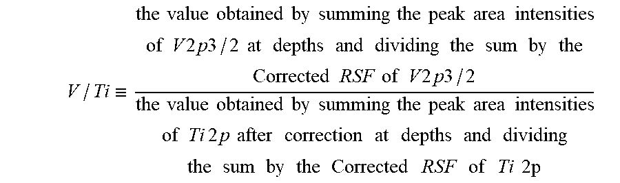
[0080] The measured value of the element ratio (molar ratio) between V and Ti in the catalyst layer obtained by XPS depth profile quantitative analysis is the ratio of the value obtained by summing the peak area intensities of V 2p3/2 at depths in the depth range of the catalyst layer in which V is detected and dividing the sum by the Corrected RSF of V 2p3/2 to the value obtained by summing the peak area intensities of Ti 2p at depths and dividing the sum by the Corrected RSF of Ti 2p, based on the following calculation formula. The depth range of the catalyst layer in which the peak area intensities of the elements are summed is, for example, the depth range from the outermost surface until the signal of Ti derived from the Ti substrate begins to be detected, when the catalyst layer is a single layer. Here, when the catalyst layer is a multilayer, the depth range is the depth range of each catalyst layer for the layers other than the catalyst layer formed directly on the Ti substrate surface, and the depth range until the signal of Ti derived from the Ti substrate begins to be detected, for the catalyst layer formed directly on the Ti substrate surface.
V / Ti .ident. the value obtained by summing the peak area intensities of V 2 p 3 / 2 at depths and dividing the sum by the Corrected RSF of V 2 p 3 / 2 the value obtained by summing the peak area intensities of Ti 2 p after correction at depths and dividing the sum by the Corrected RSF of Ti 2 p ##EQU00001##
[0081] FIG. 2 shows the results of the following four samples a to d having different element ratios (molar ratios) between V and Ti, in which the measured values of V/Ti obtained by XPS depth profile analysis by the above-described measurement method and actual values of V/Ti for the amounts of V and Ti added in coating liquids are plotted.
(Sample a) an Electrode for Electrolysis Having an Actual V/Ti Ratio Added of 0.11
[0082] An electrode for electrolysis obtained by the same method as in Example 1 described later except that a conductive substrate is coated using a coating liquid a formulated so that the element ratio (molar ratio) of ruthenium, iridium, titanium, and vanadium is 23.75:23.75:47.5:5.
(Sample b) an Electrode for Electrolysis Having an Actual V/Ti Ratio Added of 0.22
[0083] An electrode for electrolysis obtained by the same method as in Example 1 except that a conductive substrate is coated using a coating liquid b formulated so that the element ratio (molar ratio) of ruthenium, iridium, titanium, and vanadium is 22.5:22.5:45:10.
(Sample c) an Electrode for Electrolysis Having an Actual V/Ti Ratio Added of 0.35
[0084] An electrode for electrolysis obtained by the same method as in Example 1 described later. (Sample d) an electrode for electrolysis having an actual V/Ti ratio added of 1.13
[0085] An electrode for electrolysis obtained by the same method as in Example 3 described later.
[0086] As FIG. 2 showed a positive correlation between the measured and actual V/Ti values, and the element ratio (molar ratio) between V and Ti in a catalyst layer comprising ruthenium element, iridium element, titanium element and vanadium element can be obtained by referring to a calibration curve. When the components contained in the catalyst layer are changed, the element ratio (molar ratio) between V and Ti in the catalyst layer can be obtained by referring to a calibration curve of measured and actual V/Ti values by the same method.
[0087] In the electrode for electrolysis of the present embodiment, the catalyst layer may be composed of only one layer or may be a multilayer structure of two or more layers. When the catalyst layer is a multilayer structure, the content ratio of the first transition metal element contained in at least one layer therein based on 1 mol of the titanium element should be 0.25 mol or more and less than 3.4 mol, and other layers need not satisfy the content ratio.
[0088] The electrode for electrolysis of the present embodiment is characterized in that the D value being an indicator of electric double layer capacitance is 120 C/m.sup.2 or more and 420 C/m.sup.2 or less. The D value is more preferably 120 C/m.sup.2 or more and 380 C/m.sup.2 or less, further preferably 150 C/m.sup.2 or more and 360 C/m.sup.2 or less. When the D value is 120 C/m.sup.2 or more, chlorine generating overvoltage can be suppressed, and electrolysis voltage can be decreased. When the D value is 420 C/m.sup.2 or less, the durability of the ruthenium oxide can be maintained.
[0089] The D value being an indicator of electric double layer capacitance here is a value calculated using the concept of electric double layer capacitance, and it is considered that the larger the surface area of the electrode (that is, the specific surface area of the catalyst layer on the electrode) is, the larger the value is. For example, by adjusting the content of the first transition metal element in the above-described preferred range, the D value can be in the above-described range. Particularly, by increasing the content of the first transition metal element, the D value also tends to increase. By increasing calcination temperature in forming the catalyst layer (post-baking temperature), the D value tends to decrease. Specifically, the D value can be calculated using the values of electrolysis current density (A/m.sup.2) measured with respect to certain sweep rates (V/s) by a method described in Examples described later, that is, cyclic voltammetry. In more detail, an inherent current density difference (difference between current density during forward sweep and current density during backward sweep) is obtained for each sweep rate, and data are plotted with the vertical axis being the product of the current density difference and 0.3 V, the sweep range, and the horizontal axis being the sweep rate, and the slope when the plots are linearly approximated is the D value. Here, the product of the current density difference and 0.3 V, the sweep range, is well proportional to the sweep rate, and therefore the D value can be expressed by the following formula (a). By setting the D value being an indicator of electric double layer capacitance in the above-described range, overvoltage at the initial stage of electrolysis can be reduced without impairing the durability of the obtained electrode for electrolysis.
D(C/m.sup.2)=[difference in electrolysis current density(A/m.sup.2).times.0.3(V)]/[sweep rate(V/s)] (a)
[0090] When the catalyst layer in the present embodiment contains ruthenium element, iridium element, titanium element, and a first transition metal element, and further the content ratio of the first transition metal element and the titanium element is in a particular range, the function as an catalyst for electrolysis associated with an increase in the D value being an indicator of electric double layer capacitance improves, and overvoltage at the initial stage of electrolysis can be reduced.
[0091] The catalyst layer in the present embodiment may contain only the ruthenium element, the iridium element, the titanium element, and the first transition metal element described above, as constituent elements, or may comprise another metal element in addition to these. Specific examples of another metal element include, but are not limited to, elements selected from tantalum, niobium, tin, platinum, and the like. Examples of the existence form of these other metal elements include being present as metal elements contained in oxides.
[0092] When the catalyst layer in the present embodiment comprises another metal element, its content ratio is preferably 20 mol % or less, more preferably 10 mol % or less, as the molar ratio of another metal element to all metal elements contained in the catalyst layer.
[0093] The thickness of the catalyst layer in the present embodiment is preferably 0.1 to 5 .mu.m, more preferably 0.5 to 3 .mu.m. By setting the thickness of the catalyst layer at the above-described lower limit value or more, initial electrolysis performance tends to be able to be sufficiently maintained. By setting the thickness of the catalyst layer at the above-described upper limit value or less, an electrode for electrolysis excellent in economy tends to be obtained.
[0094] The catalyst layer may comprise only one layer, or the number of catalyst layers may be two or more.
[0095] When the number of catalyst layers is two or more, at least one of them should be the catalyst layer in the present embodiment. When the number of catalyst layers is two or more, at least the outermost layer is preferably the catalyst layer in the present embodiment. A mode of having two or more catalyst layers in the present embodiment with the same composition or different compositions is also preferred.
[0096] Even when the number of catalyst layers is two or more, the thickness of the catalyst layer in the present embodiment is preferably 0.1 to 5 .mu.m, more preferably 0.5 to 3 .mu.m, as described above.
(Method for Producing Electrode for Electrolysis)
[0097] Next, one example of a method for producing an electrode for electrolysis of the present embodiment will be described in detail.
[0098] The electrode for electrolysis of the present embodiment can be produced, for example, by forming a catalyst layer comprising ruthenium element, iridium element, titanium element, and a first transition metal element on a conductive substrate subjected to the above-described surface area increasing treatment. The formation of the catalyst layer is preferably performed by a thermal decomposition method.
[0099] In the production method according to the thermal decomposition method, the catalyst layer can be formed by coating a conductive substrate with a coating liquid comprising a mixture of compounds (precursors) containing the above elements followed by calcination under an oxygen-containing atmosphere for the thermal decomposition of the components in the coating liquid. According to this method, the electrode for electrolysis can be produced with high productivity in a smaller number of steps than in conventional production methods.
[0100] The thermal decomposition here means calcining metal salts or the like being precursors under an oxygen-containing atmosphere to decompose them into metal oxides or metals and gaseous substances. The obtained decomposition products can be controlled by the metal species contained in the precursors blended into the coating liquid as starting materials, the types of metal salts, the atmosphere in which thermal decomposition is performed, and the like. Usually, under an oxidizing atmosphere, many metals tend to easily form oxides. In an industrial production process of an electrode for electrolysis, thermal decomposition is usually performed in air. Also in the present embodiment, the range of oxygen concentration in calcination is not particularly limited, and performing calcination in air is sufficient. However, air may be flowed into a calcining furnace, or oxygen may be supplied, as needed.
[0101] As a preferred mode of the method for producing an electrode for electrolysis of the present embodiment, the method preferably comprises the steps of preparing a coating liquid containing a ruthenium compound, an iridium compound, a titanium compound, and a compound comprising a first transition metal element; coating at least one surface of a conductive substrate with the coating liquid to form a coating film; and calcining the coating film under an oxygen-containing atmosphere to form a catalyst layer. The ruthenium compound, the iridium compound, the titanium compound, and the compound comprising the first transition metal element correspond to precursors containing the metal elements contained in the catalyst layer in the present embodiment. An electrode for electrolysis having a uniform catalyst layer can be produced by the above-described method.
[0102] For the compounds contained in the coating liquid, the ruthenium compound, the iridium compound, and the titanium compound may be oxides but need not necessarily be oxides. For example, they may be metal salts or the like. Examples of these metal salts include, but are not limited to, any one selected from the group consisting of chloride salts, nitrates, dinitrodiammine complexes, nitrosyl nitrates, sulfates, acetates, and metal alkoxides.
[0103] Examples of the metal salt of the ruthenium compound include, but are not limited to, ruthenium chloride and ruthenium nitrate.
[0104] Examples of the metal salt of the iridium compound include, but are not limited to, iridium chloride and iridium nitrate.
[0105] Examples of the metal salt of the titanium compound include, but are not limited to, titanium tetrachloride.
[0106] For the compounds contained in the coating liquid, the compound containing the first transition metal element may be an oxide but need not necessarily be an oxide. For example, the compound is preferably one or more selected from the group consisting of an oxoacid of vanadium and a salt thereof; a chloride of vanadium; and a nitrate of vanadium.
[0107] Examples of the countercation in the above oxoacid salt can include, but are not limited to, Na.sup.+, K.sup.+, and Ca.sup.2+.
[0108] As specific examples of such compounds, specific examples of the oxoacid or the salt thereof can include sodium metavanadate, sodium orthovanadate, and potassium orthovanadate; specific examples of the chloride can include vanadium chloride; and specific examples of the nitrate can include vanadium nitrate.
[0109] The above compounds are appropriately selected and used according to the desired metal element ratio in the catalyst layer.
[0110] The coating liquid may further comprise another compound other than compounds included in the above-described compounds. Examples of another compound include, but are not limited to, metal compounds containing metal elements such as tantalum, niobium, tin, platinum, and rhodium; and organic compounds containing metal elements such as tantalum, niobium, tin, platinum, and rhodium.
[0111] The coating liquid is preferably a liquid composition obtained by dissolving or dispersing the above compound group in an appropriate solvent. The solvent of the coating liquid used here can be selected according to the types of the above compounds. For example, water; and alcohols such as butanol can be used. The total compound concentration in the coating liquid is not particularly limited but is preferably 10 to 150 g/L from the viewpoint of properly controlling the thickness of the catalyst layer.
[0112] The method for coating a surface on a conductive substrate with the coating liquid is not limited to the following, and, for example, a dipping method in which a conductive substrate is immersed in the coating liquid, a method in which the coating liquid is applied to a surface of a conductive substrate with a brush, a roll method in which a conductive substrate is passed over a sponge-like roll impregnated with the coating liquid, and an electrostatic coating method in which spray atomization is performed with a conductive substrate and the coating liquid charged with opposite charges can be used. Among these coating methods, the roll method and the electrostatic coating method are preferred from the viewpoint of being excellent in industrial productivity. A coating film of the coating liquid can be formed on at least one surface of a conductive substrate by these coating methods.
[0113] After the conductive substrate is coated with the coating liquid, the step of drying the coating film is preferably performed as needed. The coating film can be more firmly formed on the surface of the conductive substrate by this drying step. The drying conditions can be appropriately selected according to the composition and solvent species of the coating liquid, and the like. The drying step is preferably performed at a temperature of 10 to 90.degree. C. for 1 to 20 minutes.
[0114] After the coating film of the coating liquid is formed on the surface of the conductive substrate, the coating is calcined under an oxygen-containing atmosphere. The calcination temperature can be appropriately selected according to the composition and solvent species of the coating liquid. The calcination temperature is preferably 300 to 650.degree. C. When the calcination temperature is less than 300.degree. C., the decomposition of the precursors such as the ruthenium compound is insufficient, and a catalyst layer comprising ruthenium oxide and the like may not be obtained. When the calcination temperature is more than 650.degree. C., the conductive substrate may undergo oxidation, and therefore the adhesiveness of the interface between the catalyst layer and the substrate may decrease. This tendency should be regarded as important particularly when a substrate made of titanium is used as the conductive substrate.
[0115] The calcination time is preferably long. On the other hand, from the viewpoint of the productivity of the electrode, adjustment is preferably performed so that the calcination time is not excessively long. Considering these, one calcination time is preferably 5 to 60 minutes.
[0116] It is possible to repeat the steps of the coating, drying, and calcination of the catalyst layer described above a plurality of times as needed, to form the catalyst layer to the desired thickness. It is also possible to form the catalyst layer, and then further perform long time calcination as needed, to further improve the stability of the chemically, physically, and thermally extremely stable catalyst layer. As the conditions of the long time calcination, 400 to 650.degree. C. for about 30 minutes to 4 hours is preferred.
[0117] The electrode for electrolysis of the present embodiment has low overvoltage even at the initial stage of electrolysis and allows electrolysis at low voltage and low power consumption over a long period of time. Therefore, the electrode for electrolysis of the present embodiment can be used for various types of electrolysis. Particularly, the electrode for electrolysis of the present embodiment is preferably used as a chlorine generating anode and more preferably used as an anode for sodium chloride electrolysis by ion exchange membrane process.
(Electrolyzer)
[0118] An electrolyzer of the present embodiment comprises the electrode for electrolysis of the present embodiment. In this electrolyzer, initial voltage in electrolysis is reduced. FIG. 1 shows a cross-sectional schematic view according to one example of the electrolyzer of the present embodiment.
[0119] An electrolyzer 200 comprises electrolyte solutions 210, a container 220 for containing the electrolyte solutions 210, an anode 230 and a cathode 240 immersed in the electrolyte solutions 210, an ion exchange membrane 250, and wiring 260 for connecting the anode 230 and the cathode 240 to a power supply. In the electrolyzer 200, the space on the anode side divided by the ion exchange membrane 250 is referred to as an anode chamber, and the space on the cathode side is referred to as a cathode chamber. The electrolyzer of the present embodiment can be used for various types of electrolysis. As a typical example thereof, a case where the electrolyzer of the present embodiment is used for the electrolysis of an alkali chloride aqueous solution will be described below.
[0120] As the electrolyte solutions 210 supplied to the electrolyzer of the present embodiment, for example, an alkali chloride aqueous solution such as a 2.5 to 5.5 normal (N) sodium chloride aqueous solution (brine) or potassium chloride aqueous solution can be used in the anode chamber, and a dilute alkali hydroxide aqueous solution (for example, sodium hydroxide aqueous solution or potassium hydroxide aqueous solution) or water can be used in the cathode chamber.
[0121] As the anode 230, the electrode for electrolysis of the present embodiment is used.
[0122] As the ion exchange membrane 250, for example, a fluororesin film having an ion exchange group can be used. Specific examples thereof can include "Aciplex" (R) F6801 (manufactured by Asahi Kasei Corporation). As the cathode 240, a hydrogen generating cathode being an electrode obtained by coating a conductive substrate with a catalyst, or the like is used. As this cathode, a known one can be adopted. Specific examples include a cathode obtained by coating a nickel substrate with nickel, nickel oxide, an alloy of nickel and tin, a combination of activated carbon and an oxide, ruthenium oxide, platinum, or the like; and a cathode obtained by forming a coating of ruthenium oxide on a wire mesh substrate made of nickel.
[0123] The configuration of the electrolyzer of the present embodiment is not particularly limited and may be unipolar or bipolar. The materials constituting the electrolyzer are not particularly limited, but, for example, as the material of the anode chamber, titanium and the like resistant to alkali chlorides and chlorine are preferred; and as the material of the cathode chamber, nickel and the like resistant to alkali hydroxides and hydrogen are preferred.
[0124] The electrode for electrolysis of the present embodiment (the anode 230) may be disposed at an appropriate interval from the ion exchange membrane 250, and can be used without any problem even if disposed in contact with the ion exchange membrane 250. The cathode 240 may be disposed at an appropriate interval from the ion exchange membrane 250, and even a contact type electrolyzer without an interval from the ion exchange membrane 250 (zero-gap base electrolyzer) can be used without any problem.
[0125] The electrolysis conditions of the electrolyzer of the present embodiment are not particularly limited, and the electrolyzer of the present embodiment can be operated under known conditions. For example, electrolysis is preferably carried out with the electrolysis temperature adjusted at 50 to 120.degree. C. and the current density adjusted at 0.5 to 10 kA/m.sup.2.
[0126] The electrode for electrolysis of the present embodiment can decrease electrolysis voltage in sodium chloride electrolysis compared to conventional techniques. Therefore, according to the electrolyzer of the present embodiment comprising the electrode for electrolysis, power consumption required for sodium chloride electrolysis can be decreased.
[0127] Further, the electrode for electrolysis of the present embodiment has a chemically, physically, and thermally extremely stable catalyst layer and therefore is excellent in long-term durability. Thus, according to the electrolyzer of the present embodiment comprising the electrode for electrolysis, the catalytic activity of the electrode is maintained high over a long time, and high purity chlorine can be stably produced.
EXAMPLES
[0128] The present embodiment will be described in more detail below based on Examples. The present embodiment is not limited only to these Examples.
[0129] First, the evaluation methods in the Examples and Comparative Examples will be shown below.
(Sodium Chloride Electrolysis by Ion Exchange Membrane Process Test)
[0130] As an electrolytic cell, an electrolytic cell including an anode cell having an anode chamber, and a cathode cell having a cathode chamber was provided.
[0131] Each of the electrodes for electrolysis prepared in the Examples and the Comparative Examples was cut to a predetermined size (95.times.110 mm=0.01045 m.sup.2) to provide a test electrode, and the test electrode was mounted on the rib in the anode chamber of the anode cell by welding and used as an anode.
[0132] As the cathode, one obtained by coating a wire mesh substrate made of nickel with a catalyst of ruthenium oxide was used. First, an expanded substrate made of metal nickel, as a current collector, was cut to the same size as the anode and welded on the rib in the cathode chamber of the cathode cell, then a cushion mat obtained by knitting wires made of nickel was placed, and the cathode was disposed thereon.
[0133] As the gasket, a rubber gasket made of EPDM (ethylene propylene diene) was used, and an ion exchange membrane was sandwiched between the anode cell and the cathode cell. As this ion exchange membrane, a sodium chloride electrolysis cation exchange membrane "Aciplex" (R) F6801 (manufactured by Asahi Kasei Corporation) was used.
[0134] In order to measure chlorine overvoltage, a platinum wire coated with PFA (tetrafluoroethylene-perfluoroalkyl vinyl ether copolymer) in which the coating of a portion of about 1 mm at a tip was removed to expose platinum was fixed to the surface of the anode opposite to the ion exchange membrane by tying with a string made of polytetrafluoroethylene, and used as a reference electrode. During the electrolysis test, the reference electrode was supposed to give chlorine generating potential due to an atmosphere saturated with generated chlorine gas. Therefore, the result obtained by subtracting the potential of the reference electrode from the potential of the anode was evaluated as the chlorine overvoltage of the anode.
[0135] On the other hand, as electrolysis voltage, the potential difference between the cathode and the anode was measured.
[0136] In order to measure the initial electrolysis performance of the anode, for the overvoltage and the electrolysis voltage, values 7 days after the start of electrolysis were respectively measured. For the electrolysis conditions, electrolysis was performed at a current density of 6 kA/m.sup.2, a brine concentration of 205 g/L in the anode cell, a NaOH concentration of 32 wt % in the cathode cell, and a temperature of 90.degree. C. As the electrolytic rectifier, "PAD36-100LA" (manufactured by KIKUSUI ELECTRONICS CORPORATION) was used.
(Acceleration Test)
[0137] The same electrolytic cell as the above-described sodium chloride electrolysis by ion exchange membrane process test was used except that as the test electrode mounted in the anode cell, one cut to a size of 58.times.48 mm=0.002748 m.sup.2 was used.
[0138] For the electrolysis conditions, electrolysis was performed at a current density of 6 kA/m.sup.2, a brine concentration of 205 g/L in the anode cell, a NaOH concentration of 32 wt % in the cathode cell, and a temperature of 90.degree. C. In order to confirm the durability of the test electrode, a series of operations, the stop of electrolysis, water washing in the electrolytic cell (10 minutes), and the start of electrolysis, was performed at a frequency of once every 7 days, and chlorine overvoltage (anode overvoltage) was measured every 7 days after the start of electrolysis. Further, the residual ratios of Ru and Ir in the catalyst layer in the test electrode after electrolysis (100.times.content before electrolysis/content after electrolysis; %) were calculated using numerical values obtained by the X-ray fluorescence measurement (XRF) of the metal components before and after electrolysis. As the XRF measurement apparatus, Niton XL3t-800 or XL3t-800s (trade name, manufactured by Thermo Scientific) was used.
(D Value being Indicator of Electric Double Layer Capacitance)
[0139] A test electrode was cut to a size of 30.times.30 mm=0.0009 m.sup.2 and fixed to an electrolytic cell by a screw made of titanium. A platinum mesh was used for the counter electrode, and electrolysis was performed in a NaCl aqueous solution at 85 to 90.degree. C. and a brine concentration of 205 g/L at electrolysis current densities of 1 kA/m.sup.2, 2 kA/m.sup.2, and 3 kA/m.sup.2 for 5 minutes each and at 4 kA/m.sup.2 for 30 minutes so that the test anode evolved chlorine.
[0140] After the above-described electrolysis, using Ag/AgCl for a reference electrode, in the applied potential range of 0 V to 0.3 V, at sweep rates of 10 mV/s, 30 mV/s, 50 mV/s, 80 mV/s, 100 mV/s, and 150 mV/s, a cyclic voltammogram was measured, and electrolysis current density at 0.15 V that was the center of the applied potential range during forward sweep from 0 V to 0.3 V, and electrolysis current density at 0.15 V that was the center of the applied potential range during backward sweep from 0.3 V to 0 V were measured, and the difference between the two electrolysis current densities was obtained at each sweep rate described above. The product of the difference in electrolysis current density obtained at each sweep rate and 0.3 V, the sweep range, was generally directly proportional to the sweep rate, and the slope was calculated as the D value (C/m.sup.2) being an indicator of electric double layer capacitance.
Example 1
[0141] As a conductive substrate, an expanded substrate made of titanium in which the larger dimension (LW) of the opening was 6 mm, the smaller dimension (SW) of the opening was 3 mm, and the plate thickness was 1.0 mm was used. This expanded substrate was calcined in the air at 540.degree. C. for 4 hours to form an oxide film on the surface, and then subjected to acid treatment in 25 wt % sulfuric acid at 85.degree. C. for 4 hours for pretreatment for providing fine irregularities on the surface of the conductive substrate.
[0142] Next, while a ruthenium nitrate aqueous solution (manufactured by Furuya Metal Co., Ltd., ruthenium concentration 100 g/L) was cooled to 5.degree. C. or less with dry ice and stirred, titanium tetrachloride (manufactured by Wako Pure Chemical Industries, Ltd.) was added in small amounts, and then an iridium chloride aqueous solution (manufactured by TANAKA KIKINZOKU KOGYO K.K., iridium concentration 100 g/L) and vanadium(III) chloride (manufactured by KISHIDA CHEMICAL Co., Ltd.) were further added in small amounts, so that the element ratio (molar ratio) of ruthenium, iridium, titanium, and vanadium was 21.25:21.25:42.5:15. Thus, a coating liquid A1 being an aqueous solution having a total metal concentration of 100 g/L was obtained.
[0143] This coating liquid A1 was injected into the liquid-receiving vat of a coating machine, a sponge roll made of EPDM was rotated to suck up the coating liquid A1 for impregnation, and a roll made of PVC was disposed so as to be in contact with the upper portion of the sponge roll. Then, the conductive substrate subjected to the pretreatment was passed between the sponge roll made of EPDM and the roll made of PVC for coating. Immediately after the coating, the conductive substrate after the above coating was passed between two sponge rolls made of EPDM wrapped with cloths to wipe off the excess coating liquid. Then, drying was performed at 50.degree. C. for 10 minutes, and then calcination was performed in the air at 400.degree. C. for 10 minutes.
[0144] The cycle comprising the above roll coating, drying, and calcination was further repeated three times with the increased calcination temperature of 450.degree. C., and finally calcination at 520.degree. C. for 1 hour was further performed to form a blackish brown catalyst layer on the conductive substrate to make an electrode for electrolysis.
Comparative Example 1
[0145] While a ruthenium chloride aqueous solution (manufactured by TANAKA KIKINZOKU KOGYO K.K., ruthenium concentration 100 g/L) was cooled to 5.degree. C. or less with dry ice and stirred, titanium tetrachloride (manufactured by Wako Pure Chemical Industries, Ltd.) was added in small amounts, and then an iridium chloride aqueous solution (manufactured by TANAKA KIKINZOKU KOGYO K.K., iridium concentration 100 g/L) was further added in small amounts, so that the element ratio (molar ratio) of ruthenium, iridium, and titanium was 25:25:50. Thus, a coating liquid B1 being an aqueous solution having a total metal concentration of 100 g/L was obtained. An electrode for electrolysis was made by the same method as in Example 1 except that this coating liquid B1 was used, and the cycle comprising roll coating, drying, and calcination was performed with the first calcination temperature set at 440.degree. C. and then repeated three times with the increased calcination temperature of 475.degree. C., and finally calcination at 520.degree. C. for 1 hour was further performed.
Example 2
[0146] An electrode for electrolysis was made by the same method as in Example 1 except that the conductive substrate was coated using a coating liquid A2 formulated so that the element ratio (molar ratio) of ruthenium, iridium, titanium, and vanadium was 25.45:25.45:30:19.1.
Example 3
[0147] An electrode for electrolysis was made by the same method as in Example 1 except that the conductive substrate was coated using a coating liquid A3 formulated so that the element ratio (molar ratio) of ruthenium, iridium, titanium, and vanadium was 28.75:28.75:20:22.5.
Example 4
[0148] An electrode for electrolysis was made by the same method as in Example 1 except that the conductive substrate was coated using a coating liquid A4 formulated so that the element ratio (molar ratio) of ruthenium, iridium, titanium, and vanadium was 32.05:32.05:10:25.9.
Example 5
[0149] An electrode for electrolysis was made by the same method as in Example 1 except that the conductive substrate was coated using a coating liquid A5 formulated so that the element ratio (molar ratio) of ruthenium, iridium, titanium, and vanadium was 17.5:17.5:35:30.
[0150] Table 1 shows the configuration (the metal composition of the coating liquid used for the formation of the catalyst layer) of each of the electrodes for electrolysis made in Examples 1 to 5 and Comparative Example 1 respectively, together with the measured D value being an indicator of electric double layer capacitance. The unit "mol %" in the table means molar percentage (actual value of ratio of the elements added) based on all metal elements contained in the formed catalyst layer. A value of first transition metal element/Ru and a value of first transition metal element/Ti were values calculated from the actual value of ratio of the elements added.
TABLE-US-00001 TABLE 1 Metal elements [mol %] First transition First transition First transition metal metal D value Ru Ir Ti metal element element/Ru element/Ti [C/m.sup.2] Example 1 21.25 21.25 42.5 15 0.71 0.35 296 Comparative 25 25 50 0 0 0 48 Example 1 Example 2 25.45 25.45 30 19.1 0.75 0.64 161 Example 3 28.75 28.75 20 22.5 0.78 1.13 222 Example 4 32.05 32.05 10 25.9 0.81 2.59 251 Example 5 17.5 17.5 35 30 1.71 0.86 353
[Sodium Chloride Electrolysis by Ion Exchange Membrane Process Test]
[0151] The sodium chloride electrolysis by ion exchange membrane process test was carried out using the electrodes for electrolysis made in Examples 1 to 5 and Comparative Example 1 respectively. The results are shown in Table 2.
TABLE-US-00002 TABLE 2 Electrolysis Anode voltage [V] overvoltage [V] 6 kA/m.sup.2 6 kA/m.sup.2 Example 1 2.94 0.032 Comparative 2.99 0.057 Example 1 Example 2 2.94 0.034 Example 3 2.92 0.032 Example 4 2.92 0.032 Example 5 2.91 0.031
[0152] The electrolysis voltage at a current density of 6 kA/m.sup.2 was 2.94 V for Example 1 and 2, 2.92 V for Example 3 and 4, and 2.91 V for Example 5. All were extremely low values compared with 2.99 V for Comparative Example 1.
[0153] The anode overvoltage was 0.032 V for Example 1, 0.034 V for Example 2, 0.032 V for Example 3 and Example 4, and 0.031 V for Example 5. All were low values compared with 0.057 V for Comparative Example 1.
Example 6
[0154] An electrode for electrolysis was made by the same method as in Example 1 except that the conductive substrate was coated using a coating liquid A6 formulated so that the element ratio (molar ratio) of ruthenium, iridium, titanium, and vanadium was 37:33.35:11.15:18.5, and the cycle comprising roll coating, drying, and calcination was performed with the first calcination temperature set at 310.degree. C. and then repeated three times with the increased calcination temperature of 520.degree. C., and further, calcination at 520.degree. C. for 1 hour was performed.
Example 7
[0155] An electrode for electrolysis was made by the same method as in Example 1 except that the conductive substrate was coated using a coating liquid A7 formulated so that the element ratio (molar ratio) of ruthenium, iridium, titanium, and vanadium was 31.25:28.1:9.4:31.25, and the cycle comprising roll coating, drying, and calcination was performed with the first calcination temperature set at 380.degree. C. and then repeated three times with the increased calcination temperature of 450.degree. C., and further, calcination at 450.degree. C. for 1 hour was performed.
Example 8
[0156] An electrode for electrolysis was made by the same method as in Example 1 except that a ruthenium chloride aqueous solution (manufactured by TANAKA KIKINZOKU KOGYO K.K., ruthenium concentration 100 g/L) rather than the ruthenium nitrate aqueous solution was used, the conductive substrate was coated using a coating liquid A8 formulated so that the element ratio (molar ratio) of ruthenium, iridium, titanium, and vanadium was 19.6:20.2:47.09:13.11, and the cycle comprising roll coating, drying, and calcination was repeated eight times with the calcination temperatures set at 393.degree. C., and then calcination at 485.degree. C. for 1 hour was further performed.
Example 9
[0157] An electrode for electrolysis was made by the same method as in Example 1 except that a ruthenium chloride aqueous solution (manufactured by TANAKA KIKINZOKU KOGYO K.K., ruthenium concentration 100 g/L) rather than the ruthenium nitrate aqueous solution was used, cobalt(II) chloride hexahydrate (manufactured by Wako Pure Chemical Industries, Ltd.) rather than vanadium(III) chloride was used, the conductive substrate was coated using a coating liquid A9 formulated so that the element ratio (molar ratio) of ruthenium, iridium, titanium, and cobalt was 50:3:30:17, and the cycle comprising roll coating, drying, and calcination was performed with the first calcination temperature set at 440.degree. C. and then repeated three times with the increased calcination temperature of 475.degree. C., and finally calcination at 520.degree. C. for 1 hour was further performed.
Example 10
[0158] An electrode for electrolysis was made by the same method as in Example 1 except that copper(II) nitrate trihydrate (manufactured by Wako Pure Chemical Industries, Ltd.) rather than vanadium(III) chloride was used, and the conductive substrate was coated using a coating liquid A10 formulated so that the element ratio (molar ratio) of ruthenium, iridium, titanium, and copper was 32.05:32.05:10:25.9.
Example 11
[0159] An electrode for electrolysis was made by the same method as in Example 1 except that zinc(II) nitrate hexahydrate (manufactured by Wako Pure Chemical Industries, Ltd.) rather than vanadium(III) chloride was used, and the conductive substrate was coated using a coating liquid A11 formulated so that the element ratio (molar ratio) of ruthenium, iridium, titanium, and zinc was 32.05:32.05:10:25.9.
Comparative Example 2
[0160] An electrode for electrolysis was made by the same method as in Example 1 except that the conductive substrate was coated using a coating liquid B2 formulated so that the element ratio (molar ratio) of ruthenium, iridium, titanium, and vanadium was 20:18:60:2, a ruthenium chloride aqueous solution (manufactured by TANAKA KIKINZOKU KOGYO K.K., ruthenium concentration 100 g/L) was used for the formulation of the coating liquid, and the cycle comprising roll coating, drying, and calcination was performed with the first calcination temperature set at 450.degree. C., and then repeated three times with the same calcination temperatures, and further, calcination at 450.degree. C. for 1 hour was performed.
Comparative Example 3
[0161] An electrode for electrolysis was made by the same method as in Example 1 except that the conductive substrate was coated using a coating liquid B3 formulated so that the element ratio (molar ratio) of ruthenium, iridium, titanium, and vanadium was 22.7:20.5:34.1:22.7, and the cycle comprising roll coating, drying, and calcination was performed with the first calcination temperature set at 380.degree. C., and then repeated three times with the same calcination temperatures, and finally calcination at 590.degree. C. for 1 hour was further performed.
Comparative Example 4
[0162] An electrode for electrolysis was made by the same method as in Example 1 except that the conductive substrate was coated using a coating liquid B4 formulated so that the element ratio (molar ratio) of ruthenium, iridium, titanium, and vanadium was 28.6:25.7:42.8:2.9, and the cycle comprising roll coating, drying, and calcination was performed with the first calcination temperature set at 450.degree. C. and then repeated three times with the increased calcination temperature of 520.degree. C., and further, calcination at 520.degree. C. for 1 hour was performed.
Comparative Example 5
[0163] An electrode for electrolysis was made by the same method as in Example 1 except that the conductive substrate was coated using a coating liquid B5 formulated so that the element ratio (molar ratio) of ruthenium, iridium, titanium, and vanadium was 18.5:16.7:55.55:9.25, a ruthenium chloride aqueous solution (manufactured by TANAKA KIKINZOKU KOGYO K.K., ruthenium concentration 100 g/L) was used for the formulation of the coating liquid, and the cycle comprising roll coating, drying, and calcination was performed with the first calcination temperature set at 310.degree. C. and then repeated three times with the increased calcination temperature of 380.degree. C., and finally calcination at 590.degree. C. for 1 hour was further performed.
Comparative Example 6
[0164] An electrode for electrolysis was made by the same method as in Example 1 except that manganese nitrate (manufactured by Wako Pure Chemical Industries, Ltd.) was used instead of the vanadium(III) chloride in Example 1, and the conductive substrate was coated using a coating liquid B6 formulated so that the element ratio (molar ratio) of ruthenium, iridium, titanium, and manganese was 21.25:21.25:42.5:15.
Comparative Example 7
[0165] An electrode for electrolysis was made by the same method as in Example 1 except that zinc nitrate (manufactured by Wako Pure Chemical Industries, Ltd.) was used instead of the vanadium(III) chloride in Example 1, and the conductive substrate was coated using a coating liquid B7 formulated so that the element ratio (molar ratio) of ruthenium, iridium, titanium, and zinc was 21.25:21.25:42.5:15.
Comparative Example 8
[0166] An electrode for electrolysis was made by the same method as in Example 1 except that palladium nitrate (manufactured by Wako Pure Chemical Industries, Ltd.) was used instead of the vanadium(III) chloride in Example 1, the conductive substrate was coated using a coating liquid B8 formulated so that the element ratio (molar ratio) of ruthenium, iridium, titanium, and palladium was 16.9:15.4:50.8:16.9, and the cycle comprising roll coating, drying, and calcination was performed with the first calcination temperature set at 450.degree. C. and then repeated three times with the increased calcination temperature of 520.degree. C., and finally calcination at 590.degree. C. for 1 hour was further performed.
Comparative Example 9
[0167] An electrode for electrolysis was made by the same method as in Example 1 except that the conductive substrate was coated using a coating liquid B9 formulated so that the element ratio (molar ratio) of ruthenium, titanium, and vanadium was 40:40:20, a ruthenium chloride aqueous solution (manufactured by TANAKA KIKINZOKU KOGYO K.K., ruthenium concentration 100 g/L) was used for the formulation of the coating liquid, and the cycle comprising roll coating, drying, and calcination was performed with the first calcination temperature set at 440.degree. C. and then repeated three times with the increased calcination temperature of 475.degree. C., and finally calcination at 520.degree. C. for 1 hour was further performed.
[0168] Table 3 shows the configuration (the metal composition of the coating liquid used for the formation of the catalyst layer) of each of the electrodes for electrolysis made in Examples 6 to 11 and Comparative Examples 2 to 9 respectively, together with the measured D value being an indicator of electric double layer capacitance. The unit "mol %" in the table means molar percentage (feed ratio) based on all metal elements contained in the formed catalyst layer. A value of first transition metal element/Ru and a value of first transition metal element/Ti were values calculated from the feed ratio.
TABLE-US-00003 TABLE 3 Metal elements [mol %] First First First transition transition transition metal element metal metal Another element/ element/ D value Ru Ir Ti V element .sup.(*.sup.) Ru Ti [C/m.sup.2] Example 6 37 33.35 11.15 18.5 -- 0.50 1.66 139 Example 7 31.25 28.1 9.4 31.25 -- 1.00 3.32 309 Example 8 19.6 20.2 47.09 13.11 -- 0.67 0.28 304 Example 9 50 3 30 -- 17 0.34 0.57 173 Example 10 32.05 32.05 10 -- 25.9 0.81 2.59 260 Example 11 32.05 32.05 10 -- 25.9 0.81 2.59 326 Comparative Example 2 20 18 60 2 -- 0.10 0.03 48 Comparative Example 3 22.7 20.5 34.1 22.7 -- 1.00 0.67 103 Comparative Example 4 28.6 25.7 42.8 2.9 -- 0.10 0.07 33 Comparative Example 5 18.5 16.7 55.55 9.25 -- 0.50 0.17 54 Comparative Example 6 21.25 21.25 42.5 -- -- -- -- 197 Comparative Example 7 21.25 21.25 42.5 -- 15 0.71 0.35 119 Comparative Example 8 16.9 15.4 50.8 -- 16.9 1.00 0.33 35 Comparative Example 9 40 -- 40 20 -- 0.50 0.50 161 Co for Example 9, Cu for Example 10, Zn for Example 11, Zn for Comparative Example 7, Pd for Comparative Example 8
[Acceleration Test]
[0169] The acceleration test was carried out using the electrodes for electrolysis made in Examples 1 to 11 and Comparative Examples 1 to 9 respectively. The results are shown in Table 4. For Comparative Example 9, the durability of ruthenium was low, and therefore the evaluation results at the point in time when the test was stopped after 14 days are shown.
TABLE-US-00004 TABLE 4 Anode overvoltage [V] Ru residual Ir residual 6 kA/m.sup.2 ratio [%] ratio [%] After 1 day After 21 days After 21 days After 21 days Example 1 0.031 0.032 97 98 Example 2 0.034 0.036 91 93 Example 3 0.030 0.033 88 90 Example 4 0.031 0.032 83 84 Example 5 0.030 0.031 76 78 Example 6 0.035 0.034 86 90 Example 7 0.032 0.034 52 46 Example 8 0.031 0.039 96 95 Example 9 0.044 0.030 71 80 Example 10 0.045 0.036 90 95 Example 11 0.036 0.034 89 88 Comparative 0.071 0.055 95 96 Example 1 Comparative 0.070 0.064 95 98 Example 2 Comparative 0.042 0.044 84 87 Example 3 Comparative 0.110 0.093 95 96 Example 4 Comparative 0.050 0.060 91 94 Example 5 Comparative 0.072 0.048 93 96 Example 6 Comparative 0.063 0.043 99 100 Example 7 Comparative 0.045 0.076 92 94 Example 8 Comparative 0.030 0.038 .sup.(.asterisk-pseud.) 23 .sup.(.asterisk-pseud.) -- Example 9 Comparative Example 9: a value at the point in time when the test was stopped after 14 days in the test
[0170] When the acceleration test for 21 days was carried out, the followings were found.
[0171] For the electrodes for electrolysis of Examples 1 to 11, the anode overvoltage 1 day after the start of the test was 0.030 to 0.045 V, and the anode overvoltage after 21 days was 0.030 to 0.039 V. In contrast to these, for the electrodes for electrolysis of Comparative Examples 1 to 8, the anode overvoltage 1 day after the start of the test was 0.042 to 0.110 V, and the anode overvoltage after 21 days was 0.043 to 0.093 V. In this manner, it was verified that the Examples allowed electrolysis at low voltage and low power consumption at the initial stage of the electrolysis and over a long period of time, compared with the Comparative Examples.
[0172] In addition, for Examples 1 to 11, the Ru and Ir residual ratios were both high even 21 days after the start of the test, compared with Comparative Example 9 for which the anode overvoltage was at the same level, and it was verified that while the anode overvoltage was maintained low, the durability in long-term electrolysis was also sufficient.
[0173] This application claims the priority based on Japanese Patent Application No. 2016-227066 filed on Nov. 22, 2016, the contents of which are incorporated herein by reference.
INDUSTRIAL APPLICABILITY
[0174] The electrode for electrolysis of the present invention provides low chlorine generating overvoltage and allows electrolysis at low voltage and low power consumption and therefore can be preferably used in the field of sodium chloride electrolysis. Particularly, the electrode for electrolysis of the present invention is useful as an anode for sodium chloride electrolysis by ion exchange membrane process, and can produce high purity chlorine gas having low oxygen gas concentration at low voltage and low power consumption over a long period of time.
REFERENCE SIGNS LIST
[0175] 200 electrolyzer for electrolysis [0176] 210 electrolyte solution [0177] 220 container [0178] 230 anode (electrode for electrolysis) [0179] 240 cathode [0180] 250 ion exchange membrane [0181] 260 wiring
* * * * *
uspto.report is an independent third-party trademark research tool that is not affiliated, endorsed, or sponsored by the United States Patent and Trademark Office (USPTO) or any other governmental organization. The information provided by uspto.report is based on publicly available data at the time of writing and is intended for informational purposes only.
While we strive to provide accurate and up-to-date information, we do not guarantee the accuracy, completeness, reliability, or suitability of the information displayed on this site. The use of this site is at your own risk. Any reliance you place on such information is therefore strictly at your own risk.
All official trademark data, including owner information, should be verified by visiting the official USPTO website at www.uspto.gov. This site is not intended to replace professional legal advice and should not be used as a substitute for consulting with a legal professional who is knowledgeable about trademark law.