Bottle And Method Of Using
Miros; Robert H.J. ; et al.
U.S. patent application number 16/514527 was filed with the patent office on 2019-11-07 for bottle and method of using. The applicant listed for this patent is Lifetime Brands, Inc. Invention is credited to Brittany V. Ballard, Robert H.J. Miros.
| Application Number | 20190337686 16/514527 |
| Document ID | / |
| Family ID | 55955086 |
| Filed Date | 2019-11-07 |


View All Diagrams
| United States Patent Application | 20190337686 |
| Kind Code | A1 |
| Miros; Robert H.J. ; et al. | November 7, 2019 |
BOTTLE AND METHOD OF USING
Abstract
A bottle having a reclosable and resealable lid is disclosed. The bottle can have a removable pedestal base. The base can elevate the remainder of the bottle off of the surface upon which the bottle is resting. The lid can have a seal for a drinking mouthpiece outlet and a pressure equalization port. The lid can have a concave indentation or seat aligned with a hinge connecting a top of the lid to a base or rim of the lid. When opened, the seat can rest against the lid rim, opening the lid to more than a 180.degree. lid opening angle.
| Inventors: | Miros; Robert H.J.; (Fairfax, CA) ; Ballard; Brittany V.; (Novato, CA) | ||||||||||
| Applicant: |
|
||||||||||
|---|---|---|---|---|---|---|---|---|---|---|---|
| Family ID: | 55955086 | ||||||||||
| Appl. No.: | 16/514527 | ||||||||||
| Filed: | July 17, 2019 |
Related U.S. Patent Documents
| Application Number | Filing Date | Patent Number | ||
|---|---|---|---|---|
| 15492804 | Apr 20, 2017 | |||
| 16514527 | ||||
| Current U.S. Class: | 1/1 |
| Current CPC Class: | B65D 23/001 20130101; B65D 81/3841 20130101; A47G 19/2272 20130101; A45F 3/18 20130101; B65B 7/2835 20130101; B65D 43/0225 20130101; B65D 81/3846 20130101; B65D 81/3844 20130101; B65D 47/0871 20130101; B65D 1/0246 20130101 |
| International Class: | B65D 47/08 20060101 B65D047/08; B65D 43/02 20060101 B65D043/02; B65B 7/28 20060101 B65B007/28; B65D 1/02 20060101 B65D001/02; A47G 19/22 20060101 A47G019/22; A45F 3/18 20060101 A45F003/18; B65D 81/38 20060101 B65D081/38; B65D 23/00 20060101 B65D023/00 |
Claims
1. A method of sealing a bottle having a body having a reservoir, a lid assembly rotatably attachable and detachable from the body and having open and closed configurations, a spout having an elastomer and a mouthpiece lip, and a spout seal having an elastomer, the method comprising: delivering a liquid to the reservoir; forming a fluid tight seal between the spout and the body by rotatably attaching the lid assembly to the body; forming a fluid tight seal between the mouthpiece lip and the spout seal by rotatably closing the lid assembly onto itself into the closed configuration; Releasing the fluid tight seal between the mouthpiece lip and the spout seal by rotatably opening the lid assembly.
2. The method of claim 1, wherein the forming of the fluid-tight seal between the mouthpiece lip and spout seal further comprises providing a seal between elastomer of the mouthpiece lip and elastomer of the spout seal.
3. The method of claim 1, wherein the forming of the fluid-tight seal between the spout and the body further comprises providing a seal between elastomer of the spout and metal of the body.
4. The method of claim 1, wherein the spout has a mouthpiece port and a pressure equalization hole.
Description
CROSS-REFERENCE TO RELATED APPLICATION
[0001] This application is a divisional of co-pending U.S. Ser. No. 15/492,804, filed on Apr. 20, 2017.
BACKGROUND
1. Field of the Invention
[0002] The present invention relates to a bottle, and more particularly to a reclosable and resealable bottle for carrying drinking fluids. 15
2. Description of the Related Art
[0003] Insulated bottles with removable covers are available in various embodiments. Consumer concern regarding leeching of toxic chemicals into liquid contents of bottles has grown as scientific understanding of health effects from typical bottle materials, such as BPA, has improved.
[0004] Accordingly, a sturdy, reusable bottle capable of keeping contents free from contact with particular materials, such as plastics, is desired. Furthermore, a bottle with a strong seal and sturdy construction to resist leakage and endure physical abuse is also desired.
SUMMARY
[0005] A bottle having a bottle longitudinal axis is disclosed. The bottle can have a cap or lid a cap or lid indentation. The bottle can have a spout. The spout can have a mouthpiece. The mouthpiece can have an axis for part or all of the mouthpiece at an angle offset from the bottle longitudinal axis. The bottle can have a base. The base can have at least three feet. The feet can extend in a longitudinal direction beyond the longitudinal extent of the remainder of the bottle. The feet can extend radially outward from the remainder of the base. The feet can extend up from the remainder of the base.
[0006] Furthermore, a bottle is disclosed that can have a lid having a lid top and a lid base. The lid base can have a lid base radius of curvature. The bottle can have a hinge rotatably attaching the lid top to the lid base. The lid top can have a lid top indentation. The lid top indentation can be concave and have a lid top indentation radius of curvature. The lid top indentation radius of curvature can be greater than the lid base radius of curvature.
[0007] Additionally, reusable bottle is disclosed that is capable of keeping contents free from contact with particular materials, such as plastics in the lid. The bottle can have a strong seal and sturdy construction to resist leakage and endure physical abuse with minimal damage and accidental opening of the lid.
[0008] A bottle is disclosed that can have a body having a reservoir, a lid having a lid top and a lid base, and a spout fixedly attached to the lid base. The lid top can be rotatably opened with respect to the lid base. The spout can be made from an elastomer. The spout can be attached to the lid base at least in part by compressive elastomeric forces. The spout can be in sealed contact with the body. The lid top comprises an elastomeric element. The elastomeric element is in sealed contact with the spout.
[0009] The spout can be in compressive contact with a top edge of the bottle body and sealed with the elastomeric element to seal the contents of the bottle in a water tight fashion. The bottle can be configured such that the sealing of the bottle prevents contents of the reservoir from coming into contact with the lid top or the lid base, other than the elastomeric element.
[0010] The elastomeric element can have a mouthpiece seal. The compressive elastomeric forces can be at least in part compressive elastomeric forces of the spout.
[0011] The spout can have a mouthpiece port and a pressure equalization hole. The spout can have a mouthpiece axis at an angle offset from a bottle longitudinal axis.
[0012] The bottle can have a base. The base can have three or more feet. The feet can extend in a longitudinal direction beyond the longitudinal extent of the remainder of the bottle. The feet can extend radially outward from the remainder of the base. The feet can extend up from the remainder of the base.
[0013] The bottle can have a hinge rotatably attaching the lid top to the lid base. The lid top can have a lid top indentation. The lid top indentation can be concave and can have a lid top indentation radius of curvature. The lid top indentation radius of curvature can be greater than the lid base radius of curvature.
[0014] Further disclosed is a bottle that can have a body having a reservoir, a lid assembly rotatably attachable and detachable from the body, a spout comprising an elastomer, and a spout seal comprising an elastomer. The lid assembly can have opened and closed configurations. The spout can be attached to the lid assembly. The spout can form a fluid-tight seal with the body when the lid assembly is attached to the body. The spout can have a mouthpiece terminating in a mouthpiece lip. The spout seal can be attached to the lid assembly. The spout seal can form a fluid-tight seal with the spout at least at the mouthpiece lip when the lid assembly is in the closed configuration.
[0015] The fluid-tight seal between the spout and the spout seal can be a seal between elastomer of the spout and elastomer of the spout seal. The fluid-tight seal between the spout and the body can be a seal between elastomer of the spout and metal of the body.
[0016] The spout can have a mouthpiece port and a pressure equalization hole. 19
BRIEF DESCRIPTION OF THE DRAWINGS
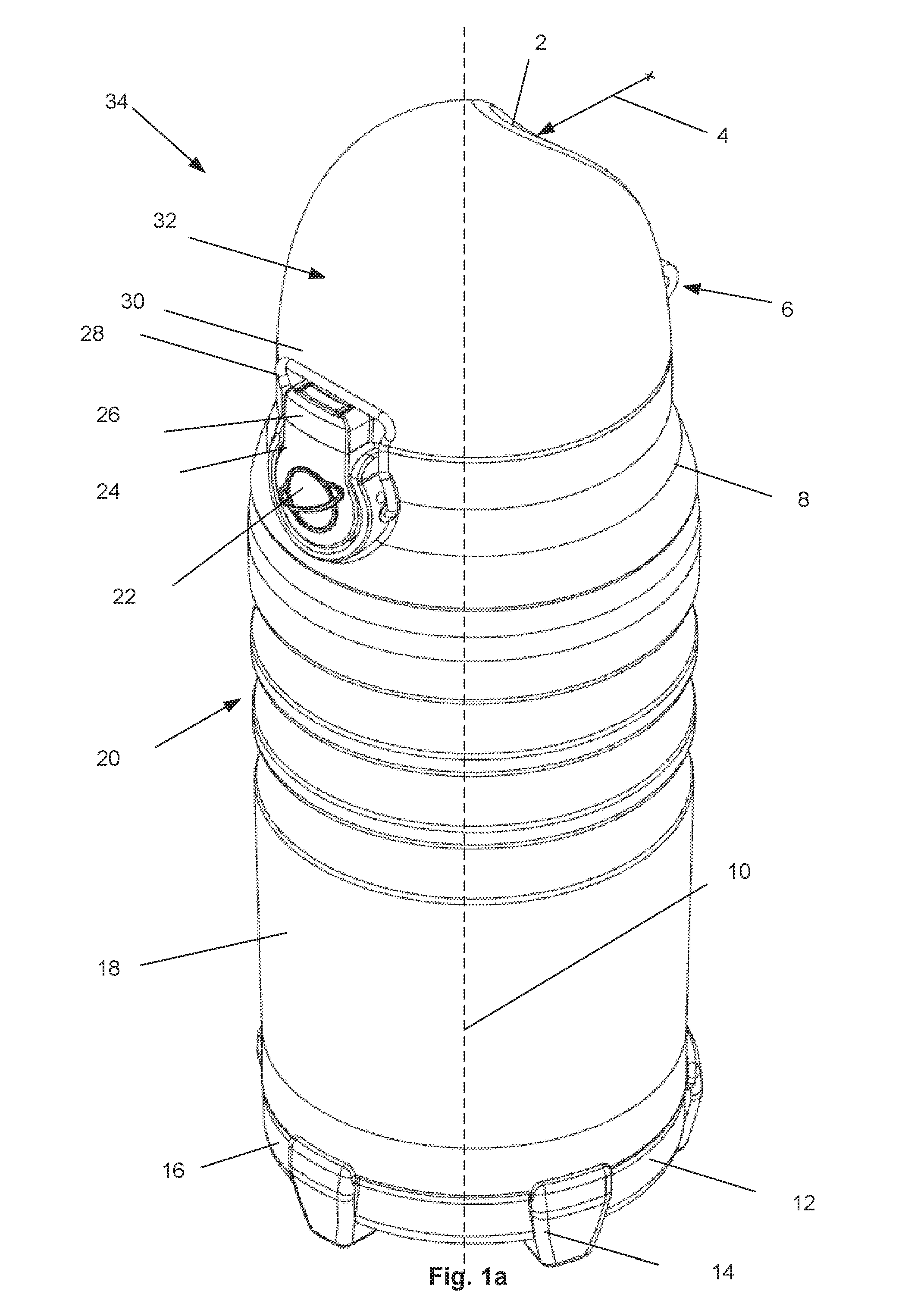
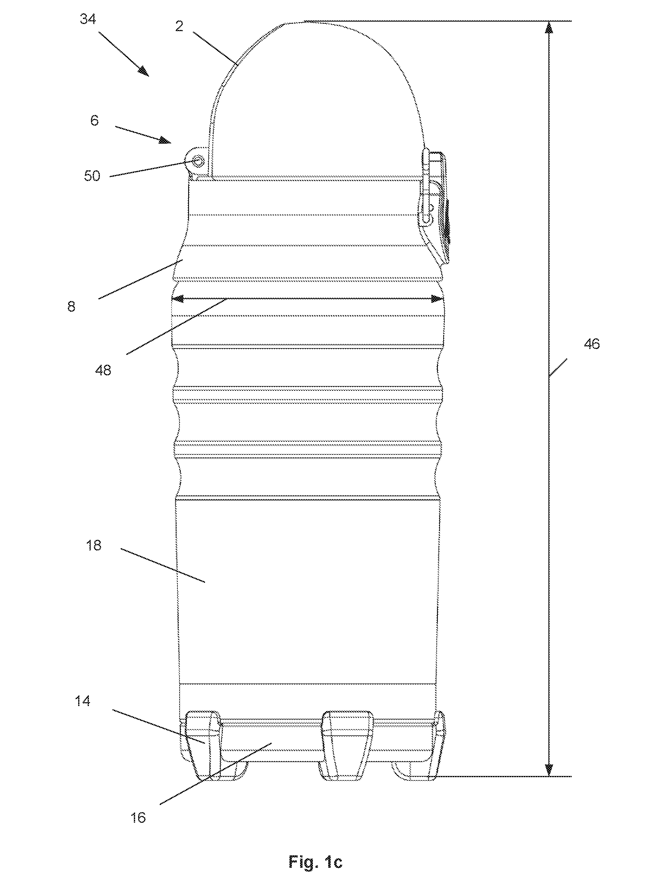
[0017] FIGS. 1a through 1e are top front perspective, front, right, rear, and left views, respectively, of a variation of the bottle in a closed configuration.
[0018] FIG. 1f is a variation of cross-sectional view A-A of FIG. 1e.
[0019] FIG. 2 is a left side view with the lid latch in an unlocked configuration.
[0020] FIG. 3 is a variation of cross-sectional view A-A with the lid release button in a released configuration.
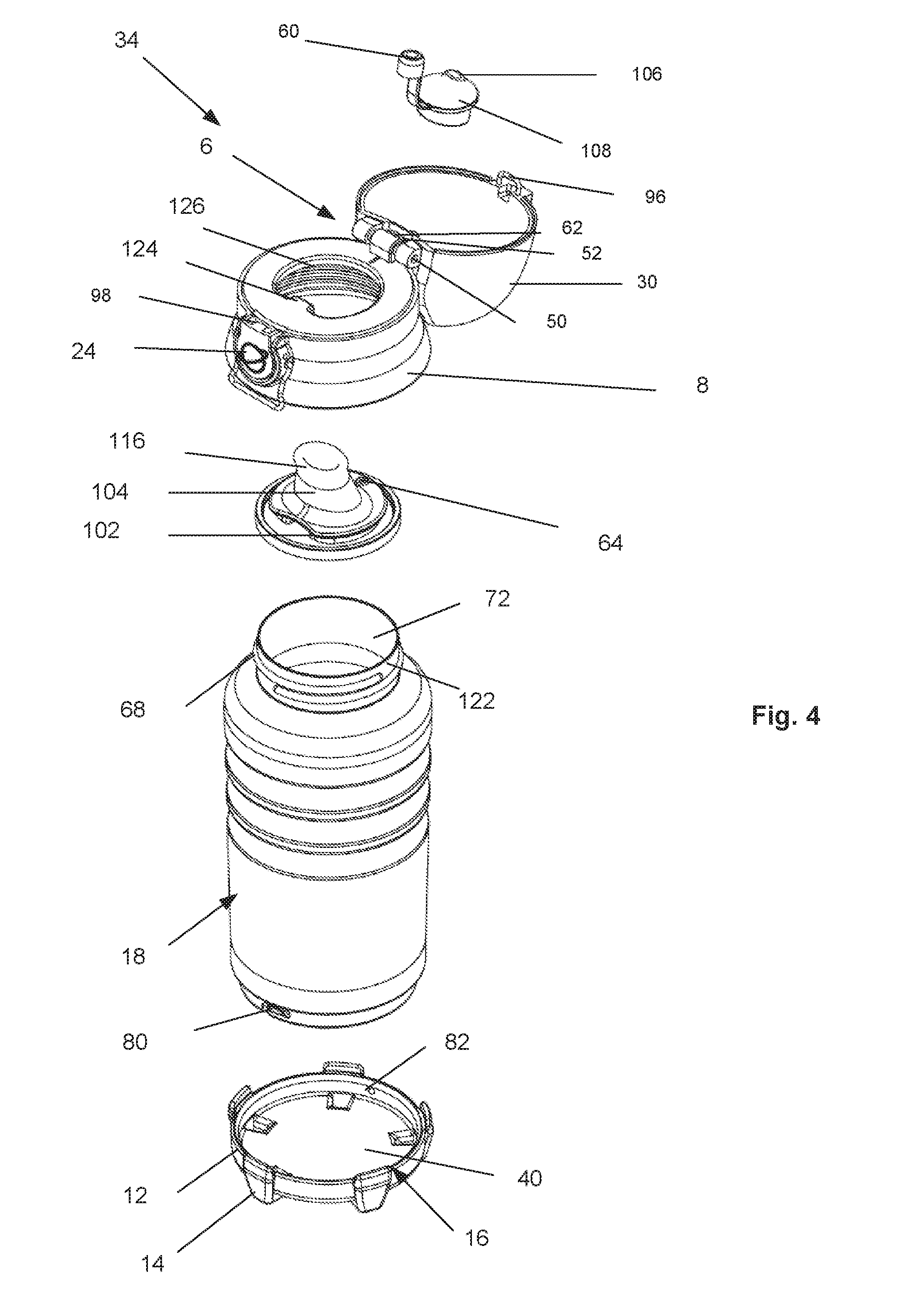
[0021] FIG. 4 is an exploded view of a variation of the bottle in an opened configuration.
[0022] FIG. 5a is a top front perspective view of a variation of the bottle in an opened configuration.
[0023] FIG. 5b is a variation of cross-sectional view B-B of FIG. 5a.
DETAILED DESCRIPTION
[0024] FIGS. 1a through 1f illustrate that a bottle 34 can have a body 18, lid 32, and base 16. The body 18 can be attached and detached from the lip and the base 16. The lip can be openable and closable. The lid 32 can be lockable. The body 18 can dispense liquid contents through the lid 32. The bottle 34 can have a bottle longitudinal axis.
[0025] The bottle 34 can have a bottle height 46 from about 4 in. to about 12 in., for example about 7.7 in. The bottle 34 can have a bottle width 48 at the maximum width of the bottle 34 from about 1.5 in. to about 5 in., for example about 2.8 in. The bottle 34 can have an empty weight from about 4 oz. to about 24 oz., for example about 8 oz.
[0026] The body 18 can have a body exterior wall 90 and a body interior wall 86. The body exterior and interior walls can be made from a plastic and/or metal, for example stainless steel, aluminum, or combinations thereof. An insulation chamber 88 can be between the body interior wall 86 and the body exterior wall 90. The insulation chamber 88 can be hollow (e.g., filled with a gas such as air, or a vacuum), or filled partially or completely with a liquid (e.g., water, anti-microbial solution such as an alcohol, saline solution, or combinations thereof), a gel, a solid (e.g., the material of the interior or exterior wall, and/or a closed-cell extruded polystyrene foam (e.g., Styrofoam from Dow Chemical Co.)), or combinations thereof.
[0027] The reservoir 74 can be closed on the sides and bottom. The top of the reservoir 74 can have a reservoir port 72. The reservoir 74 can be for example from about 100 ml to about 1 L, more narrowly from about 200 ml to about 500 ml, for example about 330 ml.
[0028] The body outer wall can have one, two, three, or more finger grooves 20 or grip rings extending around all or part of the circumference of the bottle 34. Each finger groove 20 can have a finger groove radius of curvature 38. The finger groove radius of curvature 38 can be from about 0.5 in. to about 3 in., for example about 1 in. or about 0.75 m.
[0029] The terminal bottom exterior surface of the body 18 can have a body seat 84. The body seat 84 can be flat. The terminal bottom interior surface of the body (i.e., the terminal bottom surface of the reservoir) can have a reservoir seat 78. The reservoir seat 78 can have a flat perimeter and an upwardly spherically-curved reservoir dimple 76.
[0030] The body 18 can radially example outward up from the body seat 84 and can radially example outward down from the body neck 70. The maximum bottle width 48 can be above the top-most finger groove or between two of the finger grooves.
[0031] The terminal top of the body 18 can radially taper to a body neck 70. The body neck 70 can have neck thread 68. The body neck 70 can have constant inner and outer diameters other than the neck thread 68.
[0032] The side of the body exterior wall 90 near the bottom of the reservoir 74 can have a base groove 80. The base groove 80 can be configured to removably attach to the base 16.
[0033] The lid 32 can have a lid rim 8 or lid base and a lid top 30, cover, or cap. The lid top 30 can be rotatably and lockably attached to the lid rim 8. The lid top 30 can have a rounded or domed configuration. The lid rim 8 can have a skirted or radially tapered configuration, for example expanding in radius as the lid rim 8 extends downward. The diameter of the top of the lid rim 8 and the diameter of the bottom of the lid top 30 can be substantially equal.
[0034] The lid rim 8 can have rim threads 66 configured to screw and attach to the neck thread 68 to form a fluid-tight seal. The lid rim 8 can be rotatably attached and detached from the neck 122, as well as the rest of the lid 32 from the rest of the body 18.
[0035] The lid rim 8 can have a button frame 36 extending radially outward from the remainder of the lid rim 8 and around some or all of the circumference of a lid release button 24.
[0036] The lid rim 8 can have a lid latch 28 extending out from the sides of the button frame 36. The lid latch 28 can be a wireframe rotatably attached to the button frame 36. The lid latch 28 can have two or four L-turns.
[0037] The lid release button 24 can have a button logo 22 on the face of the button. For example, the button logo 22 can be embossed or relief, for example, to increase the friction of the lid release button surface. The lid release button 24 can be rotatably attached to the remainder of the lid rim 8. For example, the lid release button 24 can have a lid release button hinge 94.
[0038] The lid release button 24 can have a lid release tab 98 extending radially inward from the top of the lid release button 24.
[0039] The lid top 30 can have a lid release catch 96. The lid top 30 can have a lid release catch frame 26. The lid release catch 96 can extend downward from the lid release catch frame 26. The lid release catch 96 can be held by the lid release tab 98 (e.g., by an interference fit) when the lid top 30 is in a closed configuration.
[0040] The lid release catch frame 26 can extend radially beyond the surrounding lid top 30. The lid latch 28 can be in tension when rotated onto the lid release catch frame 26 in a locked configuration. The lid latch 28 can compressively secure the lid top 30 to the lid rim 8.
[0041] The lid rim 8 can have a lid rim port on the reservoir port 72. The lid rim port can be on a lid rim port plane 92. The lid rim port can have a spout 104. The spout 104 can be attached to the lid rim 8 at the lid rim port. The spout 104 can have spout grommet 102, a mouthpiece 116 and a pressure equalization port. The spout 104 can be made from a soft polymer or rubber, such as food-grade silicone rubber.
[0042] The spout grommet 102 can attach to and form a fluid-tight seal around the inner perimeter of the lid rim port.
[0043] The mouthpiece 116 can be fluidly open and configured to deliver liquid from the reservoir 74 to a user. The mouthpiece 116 can have a mouthpiece front axis 110 and a mouthpiece rear axis 114. The mouthpiece front axis 110 can be at a mouthpiece front axis angle 100 to the lid rim port plane 92. The rim port plane can be perpendicular to the body longitudinal axis 10. The mouthpiece rear axis 114 can be at a mouthpiece rear axis angle 58 to the lid rim port plane 92. Either mouthpiece axis angle can be from about 45.degree. to about 135.degree., more narrowly from about 60.degree. to about 120.degree., yet more narrowly from about 75.degree. to about 90.degree., for example about 70.degree., about 75.degree., about 80.degree., or about 90.degree.. The mouthpiece axis angles can be equal, the mouthpiece front axis angle 100 can be greater than the mouthpiece rear axis angle 58, or the mouthpiece front axis angle 100 can be less than the mouthpiece rear axis angle 58. For example, the mouthpiece front axis angle 100 can be about 90.degree. and the rear axis angle can be about 75.degree..
[0044] The pressure equalization port can be in fluid communication with the reservoir 74 and the surrounding environment. When the bottle 34 is rotated with respect to gravity (e.g., from a vertical position to a declined position with the mouthpiece port 128 pointing at least downward from the horizontal), liquid in the reservoir 74 can flow from the mouthpiece 116 while gas (e.g., air) from the environment can enter the reservoir 74 through the pressure equalization port, balancing the gas pressure in the reservoir 74 with the gas pressure of the surrounding environment.
[0045] The lid top 30 can have or be removably attached to a spout seal 108. The spout seal 108 can have a pressure seal 60 and a mouthpiece seal 106. The spout seal 108, including for example the spout seal 108 and/or the pressure seal 60, can be made from the same material as the spout 104.
[0046] The pressure seal 60 can be configured to press onto and seal the pressure equalization hole 64 when the lid top 30 is in a closed configuration. The mouthpiece seal 106 can be configured to press onto and seal the mouthpiece port 128 when the lid top 30 is in a closed configuration.
[0047] The lid top 30 can have a mouthpiece seal frame 112. The mouthpiece seal frame 112 can securely attach to the mouthpiece seal 106. The lid top 30 can have a pressure seal frame 56. The pressure seal frame 56 can securely attach to the pressure seal 60. The pressure seal 60 and/or the mouthpiece seal 106 can be detached from and attached to the pressure seal frame 56 and/or mouthpiece seal frame 112, respectively, for example for cleaning or replacement.
[0048] The spout 104 can be detached from and attached to the lid rim 8, for example for cleaning or replacement.
[0049] The lid 32 can have a lid hinge 6 rotatably attaching the lid top 30 to the lid rim 8. The lid hinge 6 can have a piano hinge. For example, the lid hinge 6 can have two knuckles 54 attached to and extending from the lid top 30 and a knuckle 54 attached to and extending from the lid rim 8. The lid hinge 6 can have a hinge pin 50 extending through the knuckles 54.
[0050] The lid hinge 6 can have a lid spring catch 62 extending from the lid top 30 adjacent to the knuckle 54 extending from the lid rim 8.
[0051] The lid hinge 6 can have a lid spring 52 that can be in a closed loop. The lid spring 52 can be made from a resilient elastic material, such as a soft polymer or rubber, such as food-grade silicone rubber. The lid spring 52 can extend in (or below) the lid spring catch 62, radially outside and between two of the knuckles 54, along the radial inside of the bottom of the hinge, and radially outside and between the opposite knuckle and the central knuckle (where is continues to extend in a closed loop in or below the lid spring catch 62). The lid spring 52 can be in tension when the lid top 30 is in a closed configuration. The lid spring 52 can pull on the lid top 30 with respect to the lid rim 8 to open the lid top 30 when the lid top 30 is not latched or held to the lid rim 8, for example by the lid release tab 98 and lid release latch, or by the lid latch 28.
[0052] The lid latch 28, lid release button 24, and lid release catch 96 can be diametrically opposite from the lid hinge 6.
[0053] The lid top 30 can have a lid seat 2. The lid seat 2 can be a concave indentation on a side of the lid top 30. The angular center of the lid seat 2 can be aligned with the center of the lid hinge 6. The lid seat 2 can extend from the bottom of the lid top 30 to the vertex of the lid top 30.
[0054] The lid seat 2 can have a lid seat radius of curvature 4. The lid seat radius of curvature 4 can be from about 1 in. to about 12 in., for example about 3 in. or about 6 in.
[0055] The base 16 can have a base seat 40 on the bottom radially central portion of the base, a base rim 12 around the circumference of the base 16 and base feet 14, fins, or pedestals extending radially outward and downward from the base rim 12. The base feet 14 can extend downward past the base seat 40 by a foot extension height 42. The foot extension height 42 can be from about 0 to about 0.75 in, more narrowly from about 0.25 in. to about 0.5 in., for example about 0.375 in.
[0056] The base feet 14 can each have a base foot prong 44 extending upward from the base rim 12. The base foot prong 44 can be radially external to the body 18. For example, when the body 18 is inserted into and rotated with respect to the base 16, the body 18 can be pressed into (e.g., bump into or interference fit) the base foot prongs 44 to center the body 18 with respect to the base 16. When the body 18 and the base 16 are attached, the body 18 can contact the top of the base rim 12, the top of the base seat 40, and the inside of the base foot prongs 44.
[0057] The base 16 can have one or more base catches 82, tabs, or nubs extending radially inward from the inside of the base rim 12. The base catches 82 can be configured to slide into the base grooves 80 on the body 18. The base catches 82 can be configured to insert into the base grooves 80 to longitudinally secure the base 16 to the body 18.
[0058] The spout 104 can be in direct contact with the body interior wall 86. Contents (e.g., liquid, such as water) stored in the reservoir 74 may be in contact with only the body interior wall 86, spout 104, and spout seal 108 (for example on the mouthpiece seal) during storage, before the lid 32 is opened and the contents of the reservoir 74 are dispensed through the open spout 104 and into the outside environment (e.g., a user's mouth). Contents of the reservoir 74 may be in contact with only the materials of the body interior wall 86, spout 104, and spout seal 108, for example stainless steel and a soft polymer or rubber, such as food-grade silicone rubber, during storage of the contents.
[0059] For example, the contents may be kept out of contact with the lid 32 other than the mouthpiece seal 106--for example, being kept out of contact with plastic--during storage in the closed bottle. While the lid 32 is closed, the contents may not exit from the reservoir 74 through the pressure equalization hole 64 because of the pressure seal 60 and/or vacuum pressure in the otherwise sealed (e.g., at the spout and mouthpiece seal) reservoir 74.
[0060] FIG. 2 illustrates that the lid latch 28 can be rotated downward, as shown by arrow, into an unlocked position. The lip latch can be no longer holding the lid release catch frame 26 to the lid rim 8.
[0061] FIG. 3 illustrates that the lid release button 24 can be depressed, as shown by arrows 118, for example rotating the button around the button hinge, as shown by arrows 120, into a position releasing the lid top 30 from the lid rim 8. The depressed lid release button can rotate the lid release tab 98 radially outward from the lid release catch 96. The lid release catch 96 can then disengage and detach from the lid release tab 98. If the lid release latch is also in an unlocked configuration, the lid top 30 can then be rotated open manually and/or pulled open automatically by torque applied form the tension of the lid spring 52 onto the lid spring catch 62. The lid top 30 can rotate away from the lid rim 8, pulling away the mouthpeace seal and pressure seal 60 and exposing the open mouthpiece port 128 and pressure equalization hole 64.
[0062] The lid release button 24 can be spring-loaded to bias the lid release button 24 to a closed configuration. After the lid release button 24 is depressed and released, the lid release button 24 can return to an undepressed configuration. When the lid top 30 is rotated closed, the lid release catch 96 can press the lid release tab 98 out of the way and then reengage and re-attach to the lid release catch 96, reclosing the lid top 30 and sealing the mouthpiece 116 and pressure equalization hole 64. The lid latch 28 can then be rotated back into a locked configuration.
[0063] FIGS. 4 illustrates that the lid release catch 96 can have a U-shape. The lid release catch 96 can have a wireframe extending from the bottom of the lid top 30. The lid release catch 96 can be attached at both terminal ends to the lid top 30. The lid release catch 96 can have two right-angle turns (i.e., L-turns).
[0064] The base groove 80 can have a vertical length and an angular length around part of the circumference of the body 18. The base grooves 80 can be L-shaped. All of the base grooves 80 can be angularly spaced from each other at the same angular spacing as the base catches 82. For example, the body 18 can have two base grooves offset from each other by 180.degree., and the base 16 can have two base catches offset from each other by 180.degree..
[0065] The lid port 126 can have a lid port tab 124. The lid port tab 124 can extend into the otherwise circular lid port 126. The spout grommet 102 can seal around the lid port tab 124, as well as the remainder of the circumference of the lid port 126.
[0066] The circumference of the bottom layer of the spout grommet 102 can extend upward.
[0067] FIGS. 5a and 5b illustrate that the lid top 30 can have a lid top port plane 132. The intersection of the lid top port plane 132 and the lid rim port plane 92 can form a lid opening angle 130. When the lid top 30 is closed, the lid opening angle 130 can be about 0.degree..
[0068] When the lid top 30 is rotated open, the lid seat 2 can rest against the exterior of the lid rim 8. The lid seat radius of curvature 4 can be greater than or equal to the radius of curvature (e.g., the radius) of the lid rim 8. The lid seat 2 can be concave, allowing the lid seat 2 to open to a lid opening angle 130 of greater than about 180.degree.. For example, the lid opening angle 130 can be from about 180.degree. to about 225.degree., more narrowly from about 185.degree. to about 200.degree., for example about 190.degree.
[0069] The top terminal end of the mouthpiece 116 can have an open mouthpiece port 128. When the lid top 30 is closed, the mouthpiece seal 106 can seal the mouthpiece port 128 with a fluid-tight seal.
[0070] The variations above are for illustrative purposes and it will be apparent to those skilled in this art that various equivalent modifications or changes according to the idea of and without departing from the disclosing and teaching herein shall also fall within technical scope of the appended claims. For example, any of the materials disclosed herein can be used to make any of the elements.
[0071] Any elements described herein as singular can be pluralized (i.e., anything described as "one" can be more than one), and plural elements can be used individually. Any species element of a genus element can have the characteristics or elements of any other species element of that genus. The term "comprising" is not meant to be limiting. The above-described configurations, elements or complete assemblies and methods and their elements for carrying out the invention, and variations of aspects of the invention can be combined and modified with each other in any combination. 16
* * * * *
D00000
D00001
D00002
D00003
D00004
D00005
D00006
D00007
D00008
D00009
D00010
D00011
P00999
XML
uspto.report is an independent third-party trademark research tool that is not affiliated, endorsed, or sponsored by the United States Patent and Trademark Office (USPTO) or any other governmental organization. The information provided by uspto.report is based on publicly available data at the time of writing and is intended for informational purposes only.
While we strive to provide accurate and up-to-date information, we do not guarantee the accuracy, completeness, reliability, or suitability of the information displayed on this site. The use of this site is at your own risk. Any reliance you place on such information is therefore strictly at your own risk.
All official trademark data, including owner information, should be verified by visiting the official USPTO website at www.uspto.gov. This site is not intended to replace professional legal advice and should not be used as a substitute for consulting with a legal professional who is knowledgeable about trademark law.