Ball Structure And Manufacturing Method Thereof
WANG; Shui-Mu
U.S. patent application number 16/024922 was filed with the patent office on 2019-11-07 for ball structure and manufacturing method thereof. The applicant listed for this patent is CHAEI HSIN ENTERPRISE CO., LTD.. Invention is credited to Shui-Mu WANG.
| Application Number | 20190336830 16/024922 |
| Document ID | / |
| Family ID | 67348154 |
| Filed Date | 2019-11-07 |


View All Diagrams
| United States Patent Application | 20190336830 |
| Kind Code | A1 |
| WANG; Shui-Mu | November 7, 2019 |
BALL STRUCTURE AND MANUFACTURING METHOD THEREOF
Abstract
A ball structure includes an inner layer, at least two cover panels and a cover strip. The two cover panels are disposed on the inner layer. A groove is formed among the two cover panels adjacent to each other and the inner layer. The cover strip is engaged in the groove and connected between the two cover panels adjacent to each other.
| Inventors: | WANG; Shui-Mu; (TAICHUNG CITY, TW) | ||||||||||
| Applicant: |
|
||||||||||
|---|---|---|---|---|---|---|---|---|---|---|---|
| Family ID: | 67348154 | ||||||||||
| Appl. No.: | 16/024922 | ||||||||||
| Filed: | July 2, 2018 |
| Current U.S. Class: | 1/1 |
| Current CPC Class: | A63B 2071/0694 20130101; A63B 41/08 20130101; A63B 2243/0037 20130101; A63B 45/00 20130101 |
| International Class: | A63B 41/08 20060101 A63B041/08; A63B 45/00 20060101 A63B045/00 |
Foreign Application Data
| Date | Code | Application Number |
|---|---|---|
| May 3, 2018 | TW | 107115096 |
Claims
1. A ball structure, comprising: an inner layer; at least two cover panels disposed on the inner layer, each defining an inner surface and an outer surface, wherein a groove is formed among the two cover panels adjacent to each other and the inner layer; a cover strip engaged in the groove and connected between the two cover panels adjacent to each other; and a strip film layer adhered to the cover strip, wherein the strip film layer has a strip grain, a strip pattern or a strip color, each of the two cover panels adjacent to each other has a panel grain, a panel pattern or a panel color, wherein the strip grain is communicated with the panel grain, the strip pattern is communicated with the panel pattern, or the strip color is communicated with the panel color, wherein the cover strip comprises two convex portions, and the two convex portions cover part of the two outer surfaces of the two cover panels adjacent to each other, respectively.
2. (canceled)
3. (canceled)
4. A ball structure, comprising: an inner layer; at least two cover panels disposed on the inner layer, each defining an inner surface and an outer surface, wherein a groove is formed among the two cover panels adjacent to each other and the inner layer; a cover strip engaged in the groove, wherein the cover strip comprises a first layer and a second layer, the first layer is connected to the second layer, a hardness of the first layer is different from a hardness of the second layer, and the first layer is connected between the two cover panels adjacent to each other; and a strip film layer adhered to the first layer, wherein the strip film layer has a strip grain, a strip pattern or a strip color, each of the two cover panels adjacent to each other has a panel grain, a panel pattern or a panel color, wherein the strip grain is communicated with the panel grain, the strip pattern is communicated with the panel pattern, or the strip color is communicated with the panel color, wherein the first layer comprises two convex portions, and the two convex portions cover part of the two outer surfaces of the two cover panels adjacent to each other, respectively.
5. The ball structure of claim 4, wherein, the first layer comprises: a first outer surface; two side surfaces connected to the two cover panels adjacent to each other, respectively; and a first inner surface connected to the second layer and opposite to the first outer surface; and the second layer comprises: a second outer surface connected to the first inner surface; and a second inner surface connected to the inner layer and the second outer surface.
6. (canceled)
7. (canceled)
8. The ball structure of claim 4, further comprising: a protective layer covered outside the two cover panels and the cover strip, wherein the protective layer is transparent.
9. A manufacturing method of a ball structure, comprising: providing a cover panel forming step, wherein the cover panel forming step is for affixing at least two cover panels on an inner layer to form a groove among the inner layer and the two cover panels adjacent to each other; and providing a cover strip engaging step, wherein the cover strip engaging step is for injecting a gas into the ball structure to expand the inner layer so as to increase a width of the groove, engaging a cover strip in the groove, and then discharging the gas from the ball structure to shrink the inner layer so as to decrease the width of the groove and tightly connect the cover strip to the two cover panels.
Description
RELATED APPLICATIONS
[0001] This application claims priority to Taiwan Application Serial Number 107115096 filed on May 3, 2018, which is herein incorporated by reference.
BACKGROUND
Technical Field
[0002] The present disclosure relates to a ball structure and a manufacturing method thereof. More particularly, the present disclosure relates to a ball structure and a manufacturing method thereof having a supporting effect and a continuous pattern on a surface of the ball structure.
Description of Related Art
[0003] Game balls for sports such as basketballs, footballs, soccer balls, volleyballs, rugby balls, baseballs and softballs are well known. Many game balls, such as basketballs, typically include an inner layer, a plurality of cover panels and a cover strip. The inner layer is inflatable. The cover panels are commonly made of rubber, leather, synthetic leather or a polymeric material. The cover strip is commonly made of a filler material or rubber.
[0004] In a ball structure, a conventional technique utilizes a material of the cover strip which is harder than a material of the cover panels. The cover strip is typically engaged with the inner layer and the cover panels of the basketball, and the cover strip can facilitate a player's ability to grasp, handle, shoot, pass, dribble and otherwise control the ball during play. However, a poor touch effect of different hardness surfaces easily reduces the controllability and playability of the ball so as to increase the probability of missing during play. Moreover, the cover strip has a single color, such as black, so that the panel patterns between two cover panels adjacent to each other may not be continuous because of the cover strip. Therefore, a ball structure and a manufacturing method thereof having a supporting effect, consistent uniformity of hardness and a continuous pattern on a surface of the ball structure are commercially desirable.
SUMMARY
[0005] According to one aspect of the present disclosure, a ball structure includes an inner layer, at least two cover panels and a cover strip. The two cover panels are disposed on the inner layer. A groove is formed among the two cover panels adjacent to each other and the inner layer. The cover strip is engaged in the groove and connected between the two cover panels adjacent to each other.
[0006] According to another aspect of the present disclosure, a ball structure includes an inner layer, at least two cover panels and a cover strip. The two cover panels are disposed on the inner layer. A groove is formed among the two cover panels adjacent to each other and the inner layer. The cover strip is engaged in the groove. The cover strip includes a first layer and a second layer. The first layer is connected to the second layer. A hardness of the first layer is different from a hardness of the second layer, and the first layer is connected between the two cover panels adjacent to each other.
[0007] According to further another aspect of the present disclosure, a manufacturing method of a ball structure provides a cover panel forming step and a cover strip engaging step. The cover panel forming step is for affixing at least two cover panels on an inner layer to form a groove among the two cover panels adjacent to each other and the inner layer. The cover strip engaging step is for injecting a gas into the ball structure to expand the inner layer so as to increase a width of the groove, engaging a cover strip in the groove, and then discharging the gas from the ball structure to shrink the inner layer so as to decrease the width of the groove and tightly connect the cover strip to the two cover panels.
BRIEF DESCRIPTION OF THE DRAWINGS
[0008] The present disclosure can be more fully understood by reading the following detailed description of the embodiment, with reference made to the accompanying drawings as follows:
[0009] FIG. 1 shows a schematic view of a ball structure according to a first embodiment of the present disclosure;
[0010] FIG. 2 shows a cross-sectional view of the ball structure of FIG. 1;
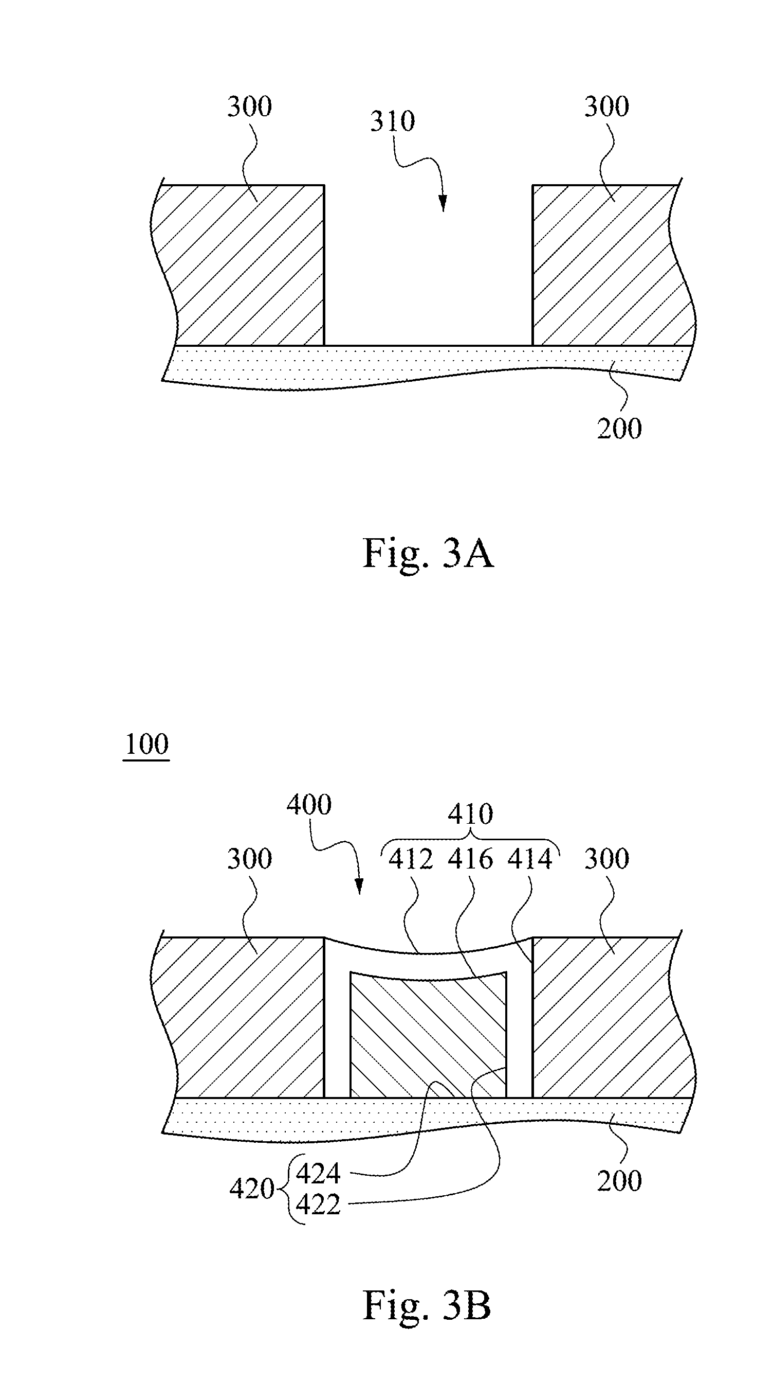
[0011] FIG. 3A shows a schematic view of a groove formed among two cover panels adjacent to each other and an inner layer of FIG. 2;
[0012] FIG. 3B shows a schematic view of the inner layer, the two cover panels and a cover strip of FIG. 2;
[0013] FIG. 4A shows a schematic view of a cover strip according to a second embodiment of the present disclosure;
[0014] FIG. 4B shows a schematic view of a cover strip according to a third embodiment of the present disclosure;
[0015] FIG. 5 shows a schematic view of an inner layer, two cover panels and a cover strip according to a fourth embodiment of the present disclosure;
[0016] FIG. 6 shows a schematic view of an inner layer, two cover panels and a cover strip according to a fifth embodiment of the present disclosure;
[0017] FIG. 7 shows a flow chart of a manufacturing method of a ball structure according to another embodiment of the present disclosure;
[0018] FIG. 8 shows a schematic view of a ball structure according to a sixth embodiment of the present disclosure;
[0019] FIG. 9 shows a flow chart of a manufacturing method of a ball structure according to further another embodiment of the present disclosure;
[0020] FIG. 10 shows a schematic view of a ball structure according to a seventh embodiment of the present disclosure;
[0021] FIG. 11 shows a schematic view of a ball structure according to an eighth embodiment of the present disclosure; and
[0022] FIG. 12 shows a schematic view of a ball structure according to a ninth embodiment of the present disclosure.
DETAILED DESCRIPTION
[0023] FIG. 1 shows a schematic view of a ball structure 100 according to a first embodiment of the present disclosure; FIG. 2 shows a cross-sectional view of the ball structure 100 of FIG. 1; FIG. 3A shows a schematic view of a groove 310 formed among two cover panels 300 adjacent to each other and an inner layer 200 of FIG. 2; and FIG. 3B shows a schematic view of the inner layer 200, the two cover panels 300 and a cover strip 400 of FIG. 2. In FIGS. 1, 2, 3A and 3B, the ball structure 100 may be a basketball and includes the inner layer 200, a plurality of cover panels 300 and a cover strip 400.
[0024] The cover panels 300 are disposed on the inner layer 200. A groove 310 is formed among every two of the cover panels 300 adjacent to each other and the inner layer 200. The cover panels 300 are made of a soft elastic material. In the embodiment of FIG. 1, the ball structure 100 is a basketball. Each of the cover panels 300 has a rugged surface.
[0025] The cover strip 400 is engaged in the groove 310. The cover strip 400 includes a first layer 410 and a second layer 420. The first layer 410 is connected to the second layer 420 and is supported by the second layer 420. A hardness of the first layer 410 is smaller than a hardness of the second layer 420 (i.e., a hard inner layer and a soft outer layer), and the first layer 410 is connected between the two cover panels 300 adjacent to each other. In detail, the first layer 410 includes a first outer surface 412, two side surfaces 414 and a first inner surface 416. The first outer surface 412 is arc-shaped and faces outwardly. The two side surfaces 414 are connected to the two cover panels 300 adjacent to each other, respectively. The first inner surface 416 is connected to the second layer 420 and opposite to the first outer surface 412. The second layer 420 includes a second outer surface 422 and a second inner surface 424. The second outer surface 422 is connected to the first inner surface 416. The second inner surface 424 is connected to the inner layer 200 and the second outer surface 422. Therefore, the ball structure 100 of the present disclosure utilizes the cover strip 400 having the soft first layer 410 and the hard second layer 420 to achieve a supporting effect.
[0026] In another embodiment, the hardness of the first layer 410 may be greater than the hardness of the second layer 420 (i.e., a soft inner layer and a hard outer layer). Accordingly, the ball structure 100 of the present disclosure utilizes the cover strip 400 having the hard first layer 410 and the soft second layer 420 to achieve the supporting effect.
[0027] FIG. 4A shows a schematic view of a cover strip 400a according to a second embodiment of the present disclosure; and FIG. 4B shows a schematic view of a cover strip 400b according to a third embodiment of the present disclosure. In FIG. 4A, the cover strip 400a includes a first layer 410a and a second layer 420a. The structure of the second layer 420a is the same as the structure of the second layer 420 of FIG. 3B and will not be described again herein. The first layer 410a includes a first outer surface 412a having a rugged shape and being arc-shaped. In FIG. 4A, the first layer 410a is made of the same material as the second layer 420a. A hardness of the first layer 410a is smaller than a hardness of the second layer 420a. In FIG. 4B, the cover strip 400b includes the first layer 410a and a second layer 420b. The structure of the second layer 420b is the same as the structure of the second layer 420 of FIG. 3B and will not be described again herein. The first layer 410a includes a first outer surface 412a having the rugged shape and the arc shape. In FIG. 4B, the first layer 410a is made of a material different from the second layer 420b. The first layer 410a and the second layer 420b are integrally injection molded. Therefore, the hardness of the first layer 410a is smaller than the hardness of the second layer 420a, 420b so as to achieve the supporting effect.
[0028] FIG. 5 shows a schematic view of an inner layer 200, two cover panels 300 and a cover strip 400c according to a fourth embodiment of the present disclosure. In FIG. 5, the structures of the inner layer 200 and the two cover panels 300 are the same as the structures of the inner layer 200 and the two cover panels 300 of FIG. 3A. The cover strip 400c includes a first layer 410c and a second layer 420c. The first layer 410c has a concave shape. The first layer 410c includes a first outer surface 412c, two first side surfaces 414c and a first inner surface 416c. The first outer surface 412c is arc-shaped. The two first side surfaces 414c are connected to the two cover panels 300 adjacent to each other, respectively. The first inner surface 416c is correspondingly connected to the second layer 420c. Moreover, the second layer 420c has a convex shape and is corresponding to the first layer 410c. The second layer 420c includes a second outer surface 422c, two second side surfaces 424c and a second inner surface 426c. The second outer surface 422c is connected to the first inner surface 416c. The two second side surfaces 424c are connected to the two cover panels 300 adjacent to each other, respectively. The second inner surface 426c is connected to the inner layer 200. Therefore, the inner layer 200 combined with the two cover panels 300 and the cover strip 400c of the present disclosure can achieve the supporting effect.
[0029] FIG. 6 shows a schematic view of an inner layer 200, two cover panels 300 and a cover strip 400d according to a fifth embodiment of the present disclosure. In FIG. 6, the structures of the inner layer 200 and the two cover panels 300 are the same as the structures of the inner layer 200 and the two cover panels 300 of FIG. 5. A difference between the cover strip 400c of FIG. 5 and the cover strip 400d of FIG. 6 is that the second outer surface 422c of the cover strip 400c of FIG. 5 has a convex shape, and the second outer surface 422d of the cover strip 400d of FIG. 6 has a flat shape. Therefore, the cover strip 400d of the present disclosure is implemented by a stacked structure having different hardness so as to achieve the supporting effect. The hardness of the first layer 410d (i.e., the upper layer) may be close to the hardness of each of the two cover panels 300.
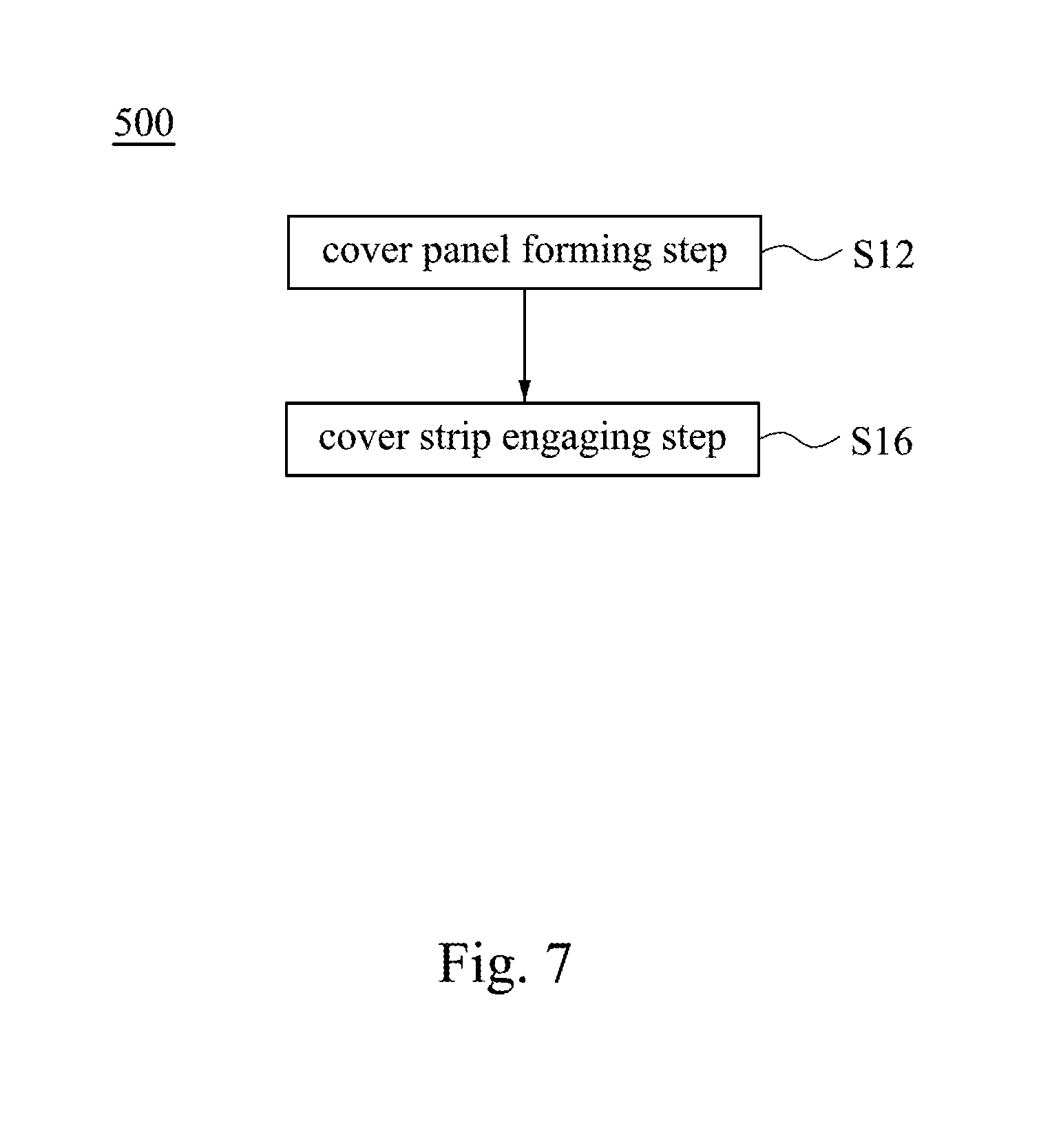
[0030] FIG. 7 shows a flow chart of a manufacturing method 500 of a ball structure 100 according to another embodiment of the present disclosure. The ball structure 100 is shown in FIG. 3B. The manufacturing method 500 of the ball structure 100 provides a cover panel forming step S12 and a cover strip engaging step S16. The cover panel forming step S12 is for affixing a plurality of cover panels 300 on an inner layer 200 to form a groove 310 among the inner layer 200 and every two of the cover panels 300 adjacent to each other. In the cover panel forming step S12, a grain, a pattern or a color of the cover panels 300 may be formed by using a digital printing method, a 3D printing method, an embossing method or a dyeing method. The cover strip engaging step S16 is for injecting a gas into the ball structure 100 to expand the inner layer 200 so as to increase a width of the groove 310, engaging a cover strip 400 in the groove 310, and then discharging the gas from the ball structure 100 to shrink the inner layer 200 so as to decrease the width of the groove 310 and tightly connect the cover strip 400 to the cover panels 300. Furthermore, the manufacturing method 500 of the present disclosure can not only produce the ball structure 100 of FIG. 3B, but also produce the ball structures of FIGS. 4A, 4B, 5 and 6. The structures of the cover strips 400, 400a, 400b, 400c, 400d are different from each other.
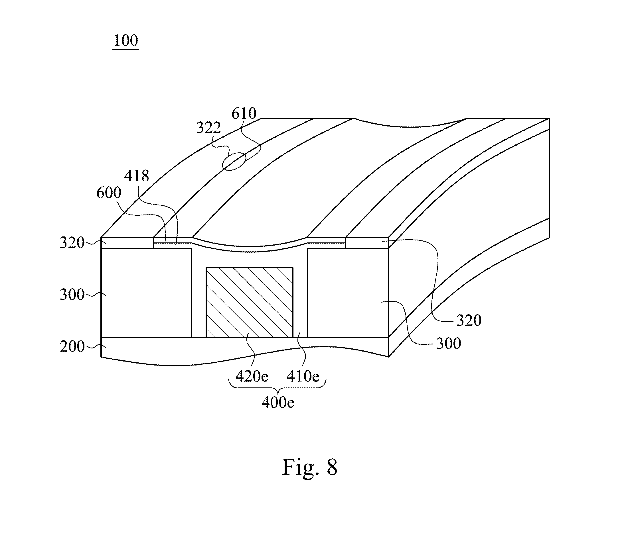
[0031] FIG. 8 shows a schematic view of a ball structure 100 according to a sixth embodiment of the present disclosure. The ball structure 100 includes an inner layer 200, a plurality of cover panels 300, a plurality of panel film layer 320, a cover strip 400e and a strip film layer 600.
[0032] In FIG. 8, the structures of the inner layer 200 and the cover panels 300 are the same as the structures of the inner layer 200 and the cover panels 300 of FIG. 3A and will not be described again herein. The ball structure 100 further includes the panel film layer 320, the cover strip 400e and the strip film layer 600. The panel film layer 320 is adhered to an upper surface of the cover panels 300 and has a panel pattern 322. The cover strip 400e includes a first layer 410e and a second layer 420e. The first layer 410e is connected to the second layer 420e. A hardness of the first layer 410e is different from a hardness of the second layer 420e. The first layer 410e is connected between the two cover panels 300 adjacent to each other. The first layer 410e of the cover strip 400e includes two convex portions 418, and the two convex portions 418 are abutted against two surfaces of the two cover panels 300 adjacent to each other, respectively. The strip film layer 600 is adhered to the first layer 410e and has a strip pattern 610. The strip pattern 610 of the strip film layer 600 is communicated with the panel pattern 322 of the panel film layer 320. Hence, the strip pattern 610 of the strip film layer 600 is consistent with the panel pattern 322 of the panel film layer 320. After injecting a gas into the ball structure 100 to expand the inner layer 200, the cover strip 400e is thermally engaged in the groove 310 to form a continuous pattern on the cover strip 400e and each of the cover panels 300 so as to solve a problem of a discontinuous pattern of a conventional technique. Moreover, in another embodiment, the strip film layer 600 has a strip grain or a strip color. Each of the two cover panels adjacent to each other has a panel grain or a panel color. The strip grain is communicated with the panel grain, or the strip color is communicated with the panel color. Accordingly, the ball structure 100 of the present disclosure utilizes the continuous pattern, the continuous grain or the continuous color on the cover strip 400e and each of the cover panels 300 to enhance integrity and consistency of the ball structure 100.
[0033] FIG. 9 shows a flow chart of a manufacturing method 500a of a ball structure 100 according to further another embodiment of the present disclosure. The ball structure 100 is shown in FIG. 8. The manufacturing method 500a of the ball structure 100 provides a cover panel forming step S22, a cover strip engaging step S26 and a film layer adhering step S28.
[0034] In FIG. 9, the detail of the cover panel forming step S22 and the cover strip engaging step S26 is the same as the cover panel forming step S12 and the cover strip engaging step S16 of FIG. 7, respectively, and will not be described again herein. The manufacturing method 500a of the ball structure 100 further provides the film layer adhering step S28 for thermally adhering the strip film layer 600 to the first layer 410e of the cover strip 400e. The strip pattern 610 of the strip film layer 600 is communicated with the panel pattern 322 of the panel film layer 320. Therefore, the manufacturing method 500a of the ball structure 100 of the present disclosure can produce the cover strip 400e having a precise size and allow the panel pattern 322 and the strip pattern 610 to communicate with each other, thereby forming the continuous pattern on the cover strip 400e and each of the cover panels 300.
[0035] FIG. 10 shows a schematic view of a ball structure 100 according to a seventh embodiment of the present disclosure. The ball structure 100 includes an inner layer 200, a plurality of cover panels 300, a plurality of panel film layer 320, a cover strip 400e, a strip film layer 600 and a protective layer 700.
[0036] In FIG. 10, the structures of the inner layer 200, the cover panels 300, the panel film layer 320, the cover strip 400e and the strip film layer 600 are the same as the structures of the inner layer 200, the cover panels 300, the panel film layer 320, the cover strip 400e and the strip film layer 600 of FIG. 8 and will not be described again herein. The ball structure 100 further includes the protective layer 700 covered outside the cover panels 300 and the cover strip 400e. The protective layer 700 is transparent. In other words, the protective layer 700 is covered outside the strip film layer 600 and the panel film layer 320, so that the strip film layer 600 and the panel film layer 320 are not affected by the external environment.
[0037] FIG. 11 shows a schematic view of a ball structure 100 according to an eighth embodiment of the present disclosure. The ball structure 100 includes an inner layer 200, a plurality of cover panels 300, a plurality of panel film layer 320, a cover strip 400f and a strip film layer 600.
[0038] In FIG. 11, the structures of the inner layer 200, the cover panels 300, the panel film layer 320 and the strip film layer 600 are the same as the structures of the inner layer 200, the cover panels 300, the panel film layer 320 and the strip film layer 600 of FIG. 8 and will not be described again herein. The ball structure 100 further includes the cover strip 400f having a single hardness and a single-layered structure. Accordingly, the ball structure 100 of the present disclosure utilizes the cover strip 400f engaged with the inner layer 200 and the cover panels 300 to achieve the supporting effect.
[0039] FIG. 12 shows a schematic view of a ball structure 100 according to a ninth embodiment of the present disclosure. The ball structure 100 includes an inner layer 200, a plurality of cover panels 300 and a cover strip 400g.
[0040] In FIG. 12, the structures of the inner layer 200 and the cover panels 300 are the same as the structures of the inner layer 200 and the cover panels 300 of FIG. 3A and will not be described again herein. The ball structure 100 further includes the cover strip 400g. The cover strip 400g includes a first layer 410g and a second layer 420g. The first layer 410g has a hollow shape. The first layer 410g includes an outer surface 412g, two side surfaces 414g, and an inner surface 416g and an inner ring surface 418g. The two side surfaces 414g are connected to the two cover panels 300 adjacent to each other, respectively. The inner surface 416g is corresponding to the outer surface 412g and is connected to the inner layer 200. The second layer 420g is surrounded by the inner ring surface 418g. The second layer 420g includes an outer ring surface 422g which is connected to the inner ring surface 418g. Therefore, the ball structure 100 of the present disclosure utilizes the cover strip 400g engaged with the inner layer 200 and the cover panels 300 to achieve the supporting effect.
[0041] According to the aforementioned embodiments and examples, the advantages of the present disclosure are described as follows.
[0042] 1. The ball structure of the present disclosure utilizes the cover strip having a single hardness, a soft inner layer combined with a hard outer layer or a hard inner layer combined with a soft outer layer to be capable of achieving the supporting effect.
[0043] 2. No mater whether the structure of the soft inner layer combined with the hard outer layer or the hard inner layer combined with the soft outer layer is manufactured by the same or different materials, the cover strip may be capable of achieving the supporting effect.
[0044] 3. In the ball structure of the present disclosure, the strip pattern may be communicated with the panel pattern. The strip grain may be communicated with the panel grain. The strip color may be communicated with the panel color. After injecting the gas into the ball structure to expand the inner layer, the cover strip is thermally engaged in the groove to form a continuous pattern, the continuous grain or the continuous color on the cover strip and each of the cover panels so as to solve a problem of a discontinuous pattern of a conventional technique and to enhance integrity and consistency of the ball structure.
[0045] 4. The protective layer of the present disclosure can be covered outside the cover panels and the cover strip, so that the strip film layer and the panel film layer are not affected by the external environment.
[0046] 5. The ball structure of the present disclosure utilizes the cover strip having different hardness in an inner-outer direction or an up-down direction to be capable of increasing the combinations of the cover panels and the cover strip.
[0047] Although the present disclosure has been described in considerable detail with reference to certain embodiments thereof, other embodiments are possible. Therefore, the spirit and scope of the appended claims should not be limited to the description of the embodiments contained herein.
[0048] It will be apparent to those skilled in the art that various modifications and variations can be made to the structure of the present disclosure without departing from the scope or spirit of the disclosure. In view of the foregoing, it is intended that the present disclosure cover modifications and variations of this disclosure provided they fall within the scope of the following claims.
* * * * *
D00000
D00001
D00002
D00003
D00004
D00005
D00006
D00007
D00008
D00009
D00010
D00011
XML
uspto.report is an independent third-party trademark research tool that is not affiliated, endorsed, or sponsored by the United States Patent and Trademark Office (USPTO) or any other governmental organization. The information provided by uspto.report is based on publicly available data at the time of writing and is intended for informational purposes only.
While we strive to provide accurate and up-to-date information, we do not guarantee the accuracy, completeness, reliability, or suitability of the information displayed on this site. The use of this site is at your own risk. Any reliance you place on such information is therefore strictly at your own risk.
All official trademark data, including owner information, should be verified by visiting the official USPTO website at www.uspto.gov. This site is not intended to replace professional legal advice and should not be used as a substitute for consulting with a legal professional who is knowledgeable about trademark law.