Sport Training Machine
HSU; CHING-LU
U.S. patent application number 15/969414 was filed with the patent office on 2019-11-07 for sport training machine. This patent application is currently assigned to GEE HOO FITEC CORP.. The applicant listed for this patent is GEE HOO FITEC CORP.. Invention is credited to CHING-LU HSU.
| Application Number | 20190336815 15/969414 |
| Document ID | / |
| Family ID | 68384513 |
| Filed Date | 2019-11-07 |


| United States Patent Application | 20190336815 |
| Kind Code | A1 |
| HSU; CHING-LU | November 7, 2019 |
SPORT TRAINING MACHINE
Abstract
A sport training machine including a machine base and at least one handle is disclosed. Wherein, the at least one handle is pivotally connected to the machine base; the at least one handle is pivotable between a first position and a second position, and the at least one handle has a grip for a user to hold; when the at least one handle is moved from the first position to the second position, a displacement of the grip in a first direction X is .DELTA.X, and a displacement of the grip in a second direction Y perpendicular to the first direction X is .DELTA.Y, which satisfies the following condition: .DELTA.X<.DELTA.Y. With the above design, it enables the user to perform upper limb stretching exercise or training sports.
| Inventors: | HSU; CHING-LU; (TAIPEI CITY, TW) | ||||||||||
| Applicant: |
|
||||||||||
|---|---|---|---|---|---|---|---|---|---|---|---|
| Assignee: | GEE HOO FITEC CORP. New Taipei City TW |
||||||||||
| Family ID: | 68384513 | ||||||||||
| Appl. No.: | 15/969414 | ||||||||||
| Filed: | May 2, 2018 |
| Current U.S. Class: | 1/1 |
| Current CPC Class: | A63B 22/0005 20151001; A63B 21/008 20130101; A63B 23/03566 20130101; A63B 22/001 20130101; A63B 2208/0233 20130101; A63B 21/0428 20130101; A63B 21/4035 20151001; A63B 22/0664 20130101; A63B 21/4034 20151001; A63B 21/00058 20130101; A63B 2022/0676 20130101; A63B 23/03533 20130101; A63B 21/151 20130101; A63B 2225/10 20130101; A63B 23/03591 20130101; A63B 22/0046 20130101; A63B 21/227 20130101; A63B 2225/09 20130101 |
| International Class: | A63B 22/00 20060101 A63B022/00; A63B 22/06 20060101 A63B022/06; A63B 21/00 20060101 A63B021/00; A63B 21/22 20060101 A63B021/22; A63B 21/04 20060101 A63B021/04 |
Claims
1. A sport training machine, comprising: a machine base; and at least one handle pivotally connected to the machine base, the at least one handle is pivotable between a first position and a second position, and the at least one handle has a grip for a user to hold; wherein, when the at least one handle is moved from the first position to the second position, a displacement of the grip in a first direction X is .DELTA.X, and a displacement of the grip in a second direction Y perpendicular to the first direction X is .DELTA.Y, which satisfies the following condition: .DELTA.X<.DELTA.Y.
2. The sport training machine as claimed in claim 1, wherein the first direction is a horizontal direction and the second direction is a vertical direction.
3. The sport training machine as claimed in claim 1, wherein a position of the grip is higher than the users shoulders when the at least one handle is at the first position, while the position of the grip is lower than the users shoulders when the at least one handle is at the second position.
4. The sport training machine as claimed in claim 3, wherein when the at least one handle is at the second position, the grip is close to the users waist and away from the users shoulders.
5. The sport training machine as claimed in claim 1, wherein the at least one handle includes a first section and a second section which are connected to each other, wherein the first section is pivotally connected to the machine base; a length of the second section of the at least one handle in a reference plane consist of the first direction and the second direction is greater than a length of the first section of the at least one handle in the reference plane; a predetermined angle is formed between the first section and the second section.
6. The sport training machine as claimed in claim 1, further comprising a seat disposed on the machine base, and the seat is adjustable to be toward or away from the at least one handle.
7. The sport training machine as claimed in claim 1, further comprising an exercise mechanism including at least one support and a rotary disk, wherein the at least one support is pivotally connected to the machine base; the at least one support has a first end and a second end corresponding to two sides of a pivoted portion thereof; a relative displacement is formed between the first end and the second end when the at least one handle swings; the first end is pivotally connected to the machine base via a linkage assembly; the rotary disk is driven to rotate when the second end moves.
8. The sport training machine as claimed in claim 7, further comprising a resistance unit connected to the support and adapted to provide a swing resistance to the support.
9. The sport training machine as claimed in claim 8, wherein the resistance unit includes a spring, wherein one end of the spring is connected to the first end of the support, and another end of the spring is connected to the machine base.
10. The sport training machine as claimed in claim 7, wherein the first end of the support is closer to the user than the second end.
11. The sport training machine as claimed in claim 7, wherein the linkage assembly includes a first link and a second link; one end of the first link is pivotally connected to the first end of the support, and another end is pivotally connected to the second link; one end of the second link is pivotally connected to the machine base.
12. The sport training machine as claimed in claim 11, wherein the second link includes a vertical rod and a cross rod; one end of the vertical rod is pivotally connected to the first link, and another end is connected to the cross rod; one end of the cross rod is pivotally connected to the machine base, and the other end is connected to a pedal.
13. The sport training machine as claimed in claim 7, wherein the exercise mechanism includes a swing member and a first belt; the swing member is pivotally connected to the machine base; both ends of the first belt are respectively connected to the second end of the support and the swing member; the first belt is adapted to drive the rotary disk.
14. The sport training machine as claimed in claim 7, wherein the exercise mechanism further includes a flywheel, and the flywheel is connected to the rotary disk with a drive connection.
15. The sport training machine as claimed in claim 7, wherein the exercise mechanism further includes a shaft and a gear; the shaft is pivotally connected to the machine base and passes through the rotary disk; the gear is connected to the shaft; the first belt is connected with the gear via a drive connection.
Description
BACKGROUND OF THE INVENTION
Technical Field
[0001] The present invention relates generally to a training machine, and more specifically to a sport training machine.
Description of Related Art
[0002] With the improvement in people's living standard, people's attention on their health is also increasing. Among them, many people would exercise to stay healthy, or to exercise to tone his body. Wherein, a training machine is one of the good choices for people to do self-training or limber up his muscles and joints since the training machine can be used indoors and a bad weather or poor air quality would not make people be unable to exercise or train his body.
[0003] Nowadays people usually have to work in the office with a sedentary posture and bury themselves in computers and desks, it is likely for people to have neck and shoulder aches because of a long-time fixed posture or a poor sitting posture. Moreover, with the development of technology, smartphones and tablets also become indispensable to modern people. After a long-time use of the smartphones and tablets, muscle tension and fatigue will be accumulated and result in shoulder and neck pains, arm-lifting difficulties, and even joint adhesion of the shoulders which cause some symptoms of frozen shoulders such as a moving angle of a shoulder joint being restricted.
BRIEF SUMMARY OF THE INVENTION
[0004] In view of the above, an object of the present invention is to provide a sport training machine which could be used by a user to limber up his muscles and joints, and particularly could be used by the user to exercise his upper limbs.
[0005] The present invention provides a sport training machine which includes a machine base and at least one handle. Wherein, the at least one handle is pivotally connected to the machine base and is pivotable between a first position and a second position; the at least one handle has a grip for a user to hold; when the at least one handle is moved from the first position to the second position, a displacement of the grip in a first direction X is .DELTA.X, and a displacement of the grip in a second direction Y perpendicular to the first direction X is .DELTA.Y, which satisfies the following condition: .DELTA.X<.DELTA.Y.
[0006] Wherein, the first direction is a horizontal direction, and the second direction is a vertical direction.
[0007] Wherein, a position of the grip is higher than the user's shoulders when the at least one handle is at the first position, while the position of the grip is lower than the user's shoulders when the at least one handle is at the second position.
[0008] Wherein, when the at least one handle is at the second position, the grip is close to the user's waist and away from the user's shoulders.
[0009] Wherein, the at least one handle includes a first section and a second section which are connected to each other; the first section is pivotally connected to the machine base; the second section includes the grip; a length of the second section of the at least one handle in a reference plane consists of the first direction and the second direction is greater than a length of the first section of the at least one handle in the reference plane; a predetermined angle is formed between the first section and the second section.
[0010] Wherein, the sport training machine further includes a seat disposed on the machine base, and the seat is adjustable to be toward or away from the at least one handle.
[0011] Wherein, the sport training machine further includes an exercise mechanism including at least one support and a rotary disk; the at least one support has a first end and a second end corresponding to two sides of a pivoted portion thereof; a relative displacement is formed between the first end and the second end when the at least one handle swings; the first end is pivotally connected to the machine base via a linkage assembly; the rotary disk is driven to rotate when the second end moves.
[0012] Wherein, the sport training machine further includes a resistance unit connected to the support and adapted to provide a swing resistance to the support.
[0013] Wherein, the resistance unit includes a spring; one end of the spring is connected to the first end of the support, and another end of the spring is connected to the machine base.
[0014] Wherein, the first end of the support is closer to the user than the second end.
[0015] Wherein, the linkage assembly includes a first link and a second link; one end of the first link is pivotally connected to the first end of the support, and another end is pivotally connected to the second link; one end of the second link is pivotally connected to the machine base.
[0016] Wherein, the second link includes a vertical rod and a cross rod; one end of the vertical rod is pivotally connected to the first link, and another end is connected to the cross rod; one end of the cross rod is pivotally connected to the machine base, and the other end is connected to a pedal.
[0017] Wherein, the exercise mechanism includes a swing member and a first belt; the swing member is pivotally connected to the machine base; both ends of the first belt are respectively connected to the second end of the support and the swing member; the first belt is adapted to drive the rotary disk.
[0018] Wherein, the exercise mechanism further includes a flywheel, and the flywheel is connected to the rotary disk with a drive connection.
[0019] Wherein, the exercise mechanism further includes a shaft and a gear; the shaft is pivotally connected to the machine base and passes through the rotary disk; the gear is connected to the shaft; the first belt is connected with the gear via a drive connection.
[0020] The advantage of the present invention is that by utilizing the movement track of the handle, it could effectively enable the user to exercise his upper limb, whereby limbering up his muscles and joints or strengthening his body so as to stay away from shoulder and neck pain, back pain and frozen shoulders.
BRIEF DESCRIPTION OF THE SEVERAL VIEWS OF THE DRAWINGS
[0021] The present invention will be best understood by referring to the following detailed description of some illustrative embodiments in conjunction with the accompanying drawings, in which
[0022] FIG. 1 is a perspective view of a sport training machine according to a first embodiment of the present invention;
[0023] FIG. 2 to FIG. 4 are side views of the sport training machine of the first embodiment;
[0024] FIG. 5 is a partial enlarged view of the sport training machine of FIG. 1; and
[0025] FIG. 6 is a perspective view of a sport training machine according to a second embodiment of the present invention.
DETAILED DESCRIPTION OF THE INVENTION
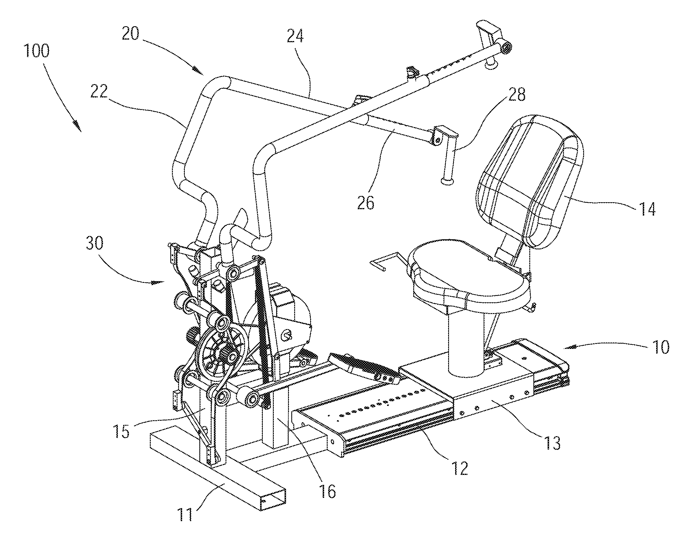
[0026] The present invention will now be described in detail with reference to a few preferred embodiments thereof as illustrated in the accompanying drawings. As shown in FIG. 1 to FIG. 3, a sport training machine 100 of a first embodiment according to the present invention includes a machine base 10, two handles 20, and an exercise mechanism 30.
[0027] In the current embodiment, the machine base 10 includes a bottom frame 11, a base 12, and a movable base 13. The base 12 is connected to the bottom frame 11. The movable base 13 is movably engaged with the base 12. A seat 14 is provided on the movable base 13 for a user to sit thereon. With the design of the movable base 13, it is capable to adjust a relative position of the seat 14 with respect to the handle 20 and the exercise mechanism 30 according to the requirements or the figure of the user. In addition, the bottom frame 11 is further provided with a first post 15 and a second post 16 for mounting the two handles 20 and the exercise mechanism 30. Furthermore, in the current embodiment, a fixing post 17 is further connected to a top of the first post 15 is further and adapted to be mounted with a dashboard 18.
[0028] The two handles 20 are pivotally connected to the machine base 10. In the current embodiment, the two handles 20 are symmetrically disposed on two sides of the first post 15, and the two handles 20 can be pivotally swung between a first position P1 and a second position P2 respectively. Since the two handles 20 have the same structure, in order to illustrate easily, one of the handles 20 is used for illustration. The handle 20 includes a first section 22 and a second section 24 which are connected to each other, wherein the first section 22 is pivotally connected to the machine base 10, and a predetermined angle is formed between the first section 22 and the second section 24. In the current embodiment, the first section 22 and the second section 24 are integrally formed as a monolithic unit of substantial L-shape, however, this is not a limitation of the present invention. For other applications, other types of the handle 20 also could be utilized. In addition, a telescopic rod 26 is connected to the second section 24 to be adjusted by the user to fit his figure or other user requirements. One end of the telescopic rod 26 is provided with a grip 28 which could be held by the user. Preferably, the grip 28 is pivotally connected to the telescopic rod 26, so that the grip 28 could be pivotally rotated according to different gripping angles of the user's hand when the user operates the handle 20.
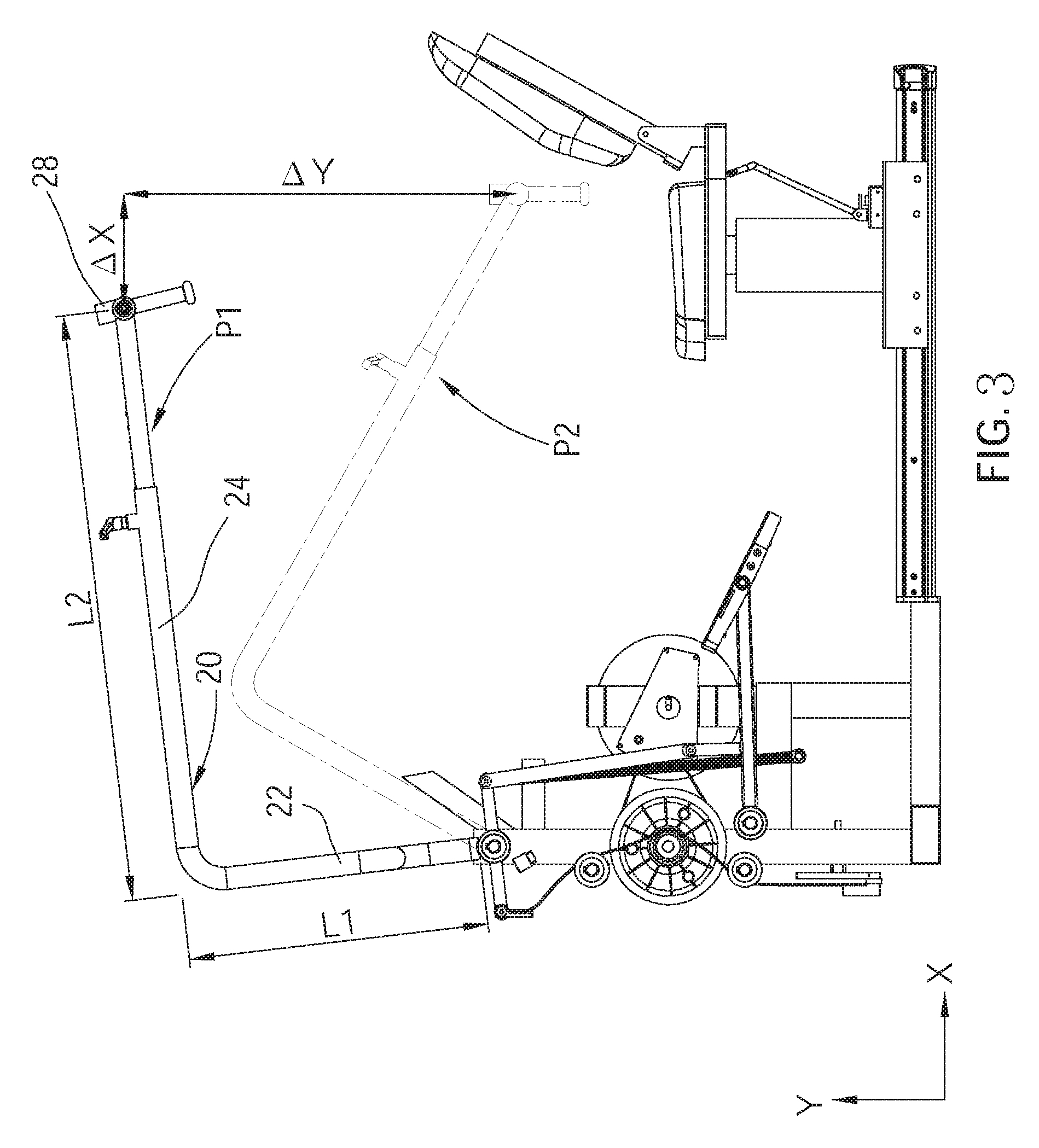
[0029] As illustrated in FIG. 2 and FIG. 3, when the handle 20 is moved from the first position P1 to the second position P2, or from the second position P2 to the first position P1, a displacement of the grip 28 in a first direction X is .DELTA.X, and a displacement of the grip 28 in a second direction Y perpendicular to the first direction X is .DELTA.Y, which satisfies the following condition: .DELTA.X<.DELTA.Y. In the current embodiment, the first direction X is a horizontal direction, and the second direction Y is a vertical direction. With the aforementioned design, the user's arm could swing with a greater range in the vertical direction than in the horizontal direction when the user operates the handle 20, thereby enabling the user to perform an upper limb exercise such as arm lifting and arm stretching down. However, in other applications, the first direction is not limited to the horizontal direction and the second direction is not limited to the vertical direction, i.e., the first direction and the second direction also could be reversed, or other directions. The above description is not a limitation of the present invention.
[0030] Meanwhile, in the current embodiment, a length L2 of the second section 24 of the handle 20 in a reference plane consists of the first direction X and the second direction Y is greater than a length L1 of the first section 22 of the handle 20 in the reference plane. With the aforementioned design, it is preferable to enable the user to perform an arm lifting or arm stretching down exercise. In addition, it is worth mentioning that, with reference to FIG. 2 and FIG. 3, a position of the grip 28 is higher than the user's shoulders when the handle 20 is at the first position P1, while the position of the grip 28 is lower than the user's shoulders when the handle 20 is at the second position. In more details, when the handle 20 is at the second position P2, the grip 28 is close to the user's waist and away from the user's shoulders. With the aforementioned design, it is favorable to enable the user to perform upper limb stretching exercise so as to exercise the upper limbs, shoulders and neck, chest muscles, back muscles, and the like.
[0031] Furthermore, since the seat 14 is movable in the current embodiment, the user can adjust a direction of the seat 14 to make the seat 14 face toward the handle 20 (as shown in FIG. 2), or to make the seat 14 face an opposite direction of the handle 20 (as shown in FIG. 4), which enables the user to choose and experience different exercise modes.
[0032] Referring to FIG. 1, FIG. 2 and FIG. 5, the exercise mechanism 30 includes a rotary disk 32, two supports 34, two linkage assemblies 40, two resistance units 50, two first belts 60, and a swing member 70.
[0033] The rotary disk 32 is pivotally connected to the machine base 10. In the current embodiment, the rotary disk 32 is pivotally connected to the first post 15 of the machine base 10 via a shaft 31, and each of both ends of the shaft 31 is connected to a gear 33, and the two gears 33 could be driven to drive the rotary disk 32 to rotate.
[0034] The two supports 34 are pivotally connected to two sides of the first post 15 of the machine base 10 respectively, and both could be driven to pivotally swing by the two handles 20. Since the two supports 34 have the same structure, in order to illustrate easily, one of the two supports 34 is used for illustration. The support 34 has a first end 34a and a second end 34b corresponding to two sides of the pivoted portion thereof, wherein the first end 34a is closer to the user or the seat 14 than the second end 34b; a relative displacement would be formed between the first end 34a and the second end 34b of the support 34 when the handle 20 swings; the first end 34a is pivotally connected to the machine base 10 via the linkage assembly. In addition, the rotary disk 32 would be driven to rotate when the second end 34b moves.
[0035] In the current embodiment, the linkage assembly 40 includes a first link 42 and a second link 44. Wherein, one end of the first link 42 is pivotally connected to the first end 34a of the support 34, and another end of the first link 42 is pivotally connected to the second link 44; one end of the second link 44 is pivotally connected to the machine base 10. In addition, the second link 44 includes a vertical rod 442 and a cross rod 444, wherein one end of the vertical rod 442 is pivotally connected to the first link 42, and another end of the vertical rod 442 is connected to the cross rod 444; one end of the cross rod 444 is pivotally connected to the machine base 10, and another end of the cross rod 444 is connected to a pedal 46 adapted for treading by the user's feet. By utilizing the design of the linkage assembly 40, it is favorable to enable the user to exercise his leg muscles together with the motion when the user operates the handle 20, which achieves an effect of whole body exercise. Particularly, the linkage assembly 40 is mounted on the first end 34a of the supports 34 which is close to the user. With the aforementioned design, the stability of the exercise mechanism 30 could be improved.
[0036] The two resistance units 50 have the same structure, in order to illustrate easily, one of the two resistance units 50 is used for illustration. The resistance unit 50 is connected to the support 34 to provide a swing resistance to the holder 34 such that the effect of exercise or rehabilitation could be enhanced. In the current embodiment, the resistance unit 50 is a spring 50 as an example, wherein both ends thereof are connected to a first end 34a of the holder 34 and the first post 15 of the machine base 10. However, in other applications, the resistance unit 50 also could be omitted. Further, in one embodiment, the resistance unit 50 could be designed to not only provide the swing resistance but also make the handle 20 or the pedal 46 to be returned to their initial positions, however, this is not a limitation of the present invention.
[0037] The swing member 70 is pivotally connected to the machine base 10. In the current embodiment, the swing member 70 is a longitudinal rod, and a middle portion thereof is pivotally connected to the first post 15 and is located in front of the first post 15. One end of each of the two belts 60 is connected to the second end 34b of the supports 34 respectively, and another end thereof is connected to one of the two ends of the swing member 70 respectively. Each of the two first belts 60 contacts with one of the gears 33 to establish a drive connection with the gear 33 such that the first belts 60 could drive the gears 33 to rotate, thereby driving the rotary disk 32 to rotate. In addition, in order to firmly fit or engage the first belts 60 to the gears 33, in the current embodiment, one idle wheel gear 62 is disposed on each of the upper and lower sides of the rotary disk 32 respectively, and is in contact with the first belt 60 to adjust a tension of the first belt 60, however, this is not a limitation of the present invention.
[0038] Meanwhile, the exercise mechanism 30 further includes a flywheel 80 disposed on a rear side of the rotary disk 32. In the current embodiment, the flywheel 80 is a magnetron flywheel as an example, and the flywheel 80 is mounted on the second post 16. A drive connection is formed between the second flywheel 80 and the rotary disk 32 through a second belt 82, which is adapted to control a rotation resistance of the rotary disk 32.
[0039] With the aforementioned design, when the user swings the two handles 20 and/or treads on the two pedals 46, the two supports 34 which are connected to the two handles 20 would be driven to swing together, and when the two supports 34 swing, the first belts 60 disposed on the two sides of the two supports 34 would be driven to move up and down, which further drive the gears 33 to rotate. The gear 33 then drives the shaft 31 and the rotary disk 32 to rotate. Wherein, in the current embodiment, the gear 33 is connected to the shaft 31 via a bearing (not shown), and the bearing is a deep groove ball bearing which has an outer side that can rotate bidirectionally and an inner side can only rotate in one direction, whereby the rotary disk 32 could be driven to rotate in the same direction when each of the gears 33 is rotated by each of the first belts 60, however, this is not a limitation of the present invention. In other applications, different bearing designs also could be utilized depending on the user's requirements.
[0040] With the aforementioned design, the sport training machine 100 of the present invention not only facilitates the user to perform upper limb exercise such as lifting, pulling up or down the arms, etc., and also enables the user to exercise with the muscles of both legs, or even the muscles of the waist, by treading on the pedals 46 synchronously such that it could provide the user both of health and fitness effects by stretching his limbs and strengthening his body. In addition, the seat 14 is designed to be rotatable. The seat 14 could be selectively orientated toward or opposite to the handle 20 and the exercise mechanism 30 depending on the user's requirement, thereby enabling the user to experience different sport modes.
[0041] Referring to FIG. 6, a sport training machine 200 of a second embodiment according to the present invention is illustrated. The structure of the sport training machine 200 is substantially the same as that of the sport training machine 100 of the first embodiment. The difference is that the exercise mechanism of the sport training machine 200 mainly includes two first resistance assemblies 220 and two second resistance assemblies 230, wherein the two first resistance assemblies 220 are connected to two ends of each of first supports 210 respectively, and the two second resistance assemblies 230 are connected to two ends of each of second supports 210 respectively; the first resistance assemblies 220 and the second resistance assemblies 230 could be hydraulic cylinders or pneumatic cylinders, however, this is not a limitation of the present invention. By utilizing the design of the aforementioned first resistance assemblies 220 and the second resistance assemblies 230, it is favorable to provide exercise resistance or swing resistance to the user during operating the sport training machine 200.
[0042] It must be pointed out that the embodiments described above are only some embodiments of the present invention. In practice, it is not necessary for the sport training machine to include two handles and could include only one handle. When there is only one handle, the sport training machine is provided with one support, one linkage assembly, one first belt and one resistance unit, and is not limited to the pair of components of the aforementioned embodiments. In addition, in the aforementioned embodiment, the sport training machine is an exercise bike as an example, and therefore a seat is designed for the user to sit thereon. However, the exercise bike is not a limitation of the present invention. In other applications, other types of sport training machine such as horizontal bikes, elliptical trainers, etc. also could be utilized. All equivalent structures which employ the concepts disclosed in this specification and the appended claims should fall within the scope of the present invention.
* * * * *
D00000
D00001
D00002
D00003
D00004
D00005
D00006
XML
uspto.report is an independent third-party trademark research tool that is not affiliated, endorsed, or sponsored by the United States Patent and Trademark Office (USPTO) or any other governmental organization. The information provided by uspto.report is based on publicly available data at the time of writing and is intended for informational purposes only.
While we strive to provide accurate and up-to-date information, we do not guarantee the accuracy, completeness, reliability, or suitability of the information displayed on this site. The use of this site is at your own risk. Any reliance you place on such information is therefore strictly at your own risk.
All official trademark data, including owner information, should be verified by visiting the official USPTO website at www.uspto.gov. This site is not intended to replace professional legal advice and should not be used as a substitute for consulting with a legal professional who is knowledgeable about trademark law.