Fixation Of Orthopaedic Devices
Stalcup; Gregory C. ; et al.
U.S. patent application number 16/511175 was filed with the patent office on 2019-11-07 for fixation of orthopaedic devices. This patent application is currently assigned to SMed-TA/TD, LLC. The applicant listed for this patent is SMed-TA/TD, LLC. Invention is credited to Joseph W. Jurick, Troy D. Knapp, Paul S. Nebosky, Gregory C. Stalcup, Kreigh R. Williams.
| Application Number | 20190336656 16/511175 |
| Document ID | / |
| Family ID | 51531152 |
| Filed Date | 2019-11-07 |


| United States Patent Application | 20190336656 |
| Kind Code | A1 |
| Stalcup; Gregory C. ; et al. | November 7, 2019 |
FIXATION OF ORTHOPAEDIC DEVICES
Abstract
An orthopaedic implant includes a bone screw having a surface with a plurality of threads extending from the surface and a plurality of holes formed through the surface and located between the threads. The bone screw defines an inner chamber that is in communication with the holes. A fixation material is placed in the inner chamber and configured to chemoattract tissue surrounding the bone screw following implantation to fill in at least some of the holes.
| Inventors: | Stalcup; Gregory C.; (Fort Wayne, IN) ; Knapp; Troy D.; (Alachua, FL) ; Jurick; Joseph W.; (Fort Wayne, IN) ; Nebosky; Paul S.; (Fort Wayne, IN) ; Williams; Kreigh R.; (Fort Wayne, IN) | ||||||||||
| Applicant: |
|
||||||||||
|---|---|---|---|---|---|---|---|---|---|---|---|
| Assignee: | SMed-TA/TD, LLC Columbia City IN |
||||||||||
| Family ID: | 51531152 | ||||||||||
| Appl. No.: | 16/511175 | ||||||||||
| Filed: | July 15, 2019 |
Related U.S. Patent Documents
| Application Number | Filing Date | Patent Number | ||
|---|---|---|---|---|
| 15602778 | May 23, 2017 | 10350332 | ||
| 16511175 | ||||
| 14204129 | Mar 11, 2014 | |||
| 15602778 | ||||
| 61787507 | Mar 15, 2013 | |||
| Current U.S. Class: | 1/1 |
| Current CPC Class: | A61L 31/06 20130101; A61B 17/8028 20130101; A61B 2017/8655 20130101; A61L 31/16 20130101; A61L 2300/404 20130101; A61L 31/022 20130101; C08L 71/00 20130101; A61L 31/146 20130101; A61L 2300/414 20130101; A61L 31/06 20130101; A61L 2400/18 20130101; A61B 17/8625 20130101; A61B 17/846 20130101; A61L 2300/41 20130101; A61B 17/7098 20130101 |
| International Class: | A61L 31/14 20060101 A61L031/14; A61L 31/02 20060101 A61L031/02; A61L 31/06 20060101 A61L031/06; A61B 17/80 20060101 A61B017/80; A61B 17/84 20060101 A61B017/84; A61B 17/70 20060101 A61B017/70; A61L 31/16 20060101 A61L031/16; A61B 17/86 20060101 A61B017/86 |
Claims
1. An orthopaedic implant, comprising: a bone screw having a surface with a plurality of threads extending from the surface and a plurality of holes formed through the surface and located between the threads, the bone screw defining an inner chamber that is in communication with the holes; and a fixation material placed in the inner chamber and configured to chemoattract tissue surrounding the bone screw following implantation to fill in at least some of the holes.
2. The orthopaedic implant of claim 1, wherein the bone screw defines a wall thickness in a range of 1 mm to 1.5 mm.
3. The orthopaedic implant of claim 1, wherein the holes are located axially in valleys between the threads and go through to a centerline of the bone screw.
4. The orthopaedic implant of claim 1, wherein the holes are placed along a full length of the bone screw.
5. The orthopaedic implant of claim 1, wherein the holes are concentrated near a distal end of the bone screw.
6. A method of forming an orthopaedic implant, the method comprising: adhering a fixation material to a screw blank; and cutting a plurality of threads into the screw blank and the adhered fixation material to form a completed orthopaedic implant.
7. The method of claim 6, wherein each of the threads are composed of half fixation material and half material of the screw blank.
8. The method of claim 6, wherein the fixation material is porous and comprises at least one titanium, cobalt chrome, stainless steel, polyether ether ketone, polylactic acid, polyglycolic acid, or polyethylene.
9. The method of claim 6, wherein the fixation material has pores that include at least one biologically active substance.
10. The method of claim 6, wherein adhering the fixation material to the screw blank comprises filling elongated pockets formed in the screw blank with the fixation material.
11. The method of claim 6, wherein adhering the fixation material to the screw blank comprises bonding the fixation material to the screw blank.
Description
CROSS REFERENCE TO RELATED APPLICATIONS
[0001] This is a continuation of U.S. patent application Ser. No. 15/602,778, entitled "FIXATION OF ORTHOPAEDIC DEVICES," filed May 23, 2017, which is incorporated herein by reference. U.S. patent application Ser. No. 15/602,778 is a division of U.S. patent application Ser. No. 14/204,129, entitled "FIXATION OF ORTHOPAEDIC DEVICES," filed Mar. 11, 2014, which is incorporated herein by reference. U.S. patent application Ser. No. 14/204,129 is a non-provisional application based upon U.S. provisional patent application Ser. No. 61/787,507, entitled "FIXATION OF ORTHOPAEDIC DEVICES", filed Mar. 15, 2013, which is incorporated herein by reference.
BACKGROUND OF THE INVENTION
1. Field of the Invention
[0002] The present invention relates to orthopaedic devices, and more particularly, to orthopaedic implants.
2. Description of the Related Art
[0003] Orthopaedic implants are known that are implanted into the body to achieve various surgical objectives. Such implants include bone pins, bone screws and bone plates. The implantation period of the implant can vary from a short period, such as a couple of days, to the end of a patient's life. During the implantation period, the implant will experience natural forces caused by surrounding anatomy structures due to static and dynamic conditions of the anatomy structures. These natural forces can cause the implant to either loosen from the implantation site or, worse, ultimately detach from the implant site.
[0004] To prevent the loosening and detachment of an orthopaedic implant from its implantation site, the implant is usually fixated to the implantation site by bone screws, which must be screwed into the implantation site. The implant can also be bonded to the implantation site with an adhesive, such as bone cement, or materials can be attached to the implant that encourage natural ingrowth of tissue onto or into the implant. Natural tissue ingrowth will help to fixate the implant in place and can form a strong bond with the implant.
[0005] One problem that arises with implanted devices is that there is a risk that a revision surgery, to remove the implant, may be required due to reasons such as an incorrect placement, an unforeseen event or an infection causing the implant to prematurely fail. In such cases, removing the implant can be a traumatic event for anatomy structures around the site if a lot of force is required to loosen the implant and remove it.
[0006] A similar problem can occur with devices that are meant to be temporary, i.e., have a relatively short implantation period. The device can become too integrated with the body and become very difficult to remove, which can lead to trauma at the implantation site during removal.
[0007] What is needed in the art is an orthopaedic implant that can resist natural pull out but does not require excessive force to remove.
SUMMARY OF THE INVENTION
[0008] The present invention provides an orthopaedic implant with a fixation material attached to the implant that is configured to provide a minimally sufficient adhesive force to resist natural pull out of the implant caused by forces acting on the implant during implantation and bone ingrowth.
[0009] The invention in one form is directed to an orthopaedic implant that includes a bone screw having a surface with a plurality of threads extending from the surface and a plurality of holes formed through the surface and located between the threads. The bone screw defines an inner chamber that is in communication with the holes. A fixation material is placed in the inner chamber and configured to chemoattract tissue surrounding the bone screw following implantation to fill in at least some of the holes.
[0010] The invention in another form is directed to a method of forming an orthopaedic implant. The method includes adhering a fixation material to a screw blank and cutting a plurality of threads into the screw blank and the adhered fixation material to form a completed orthopaedic implant.
[0011] An advantage of the present invention is that it provides an orthopaedic implant that can withstand natural pull out forces when implanted within a patient while not requiring excessive force to remove, if necessary.
BRIEF DESCRIPTION OF THE DRAWINGS
[0012] The above-mentioned and other features and advantages of this invention, and the manner of attaining them, will become more apparent and the invention will be better understood by reference to the following description of embodiments of the invention taken in conjunction with the accompanying drawings, wherein:
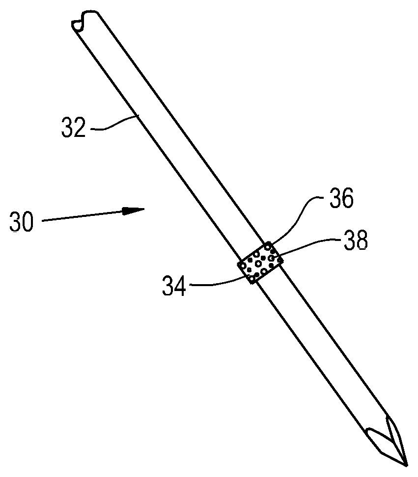
[0013] FIG. 1 is a perspective view of an embodiment of an orthopaedic implant of the present invention;
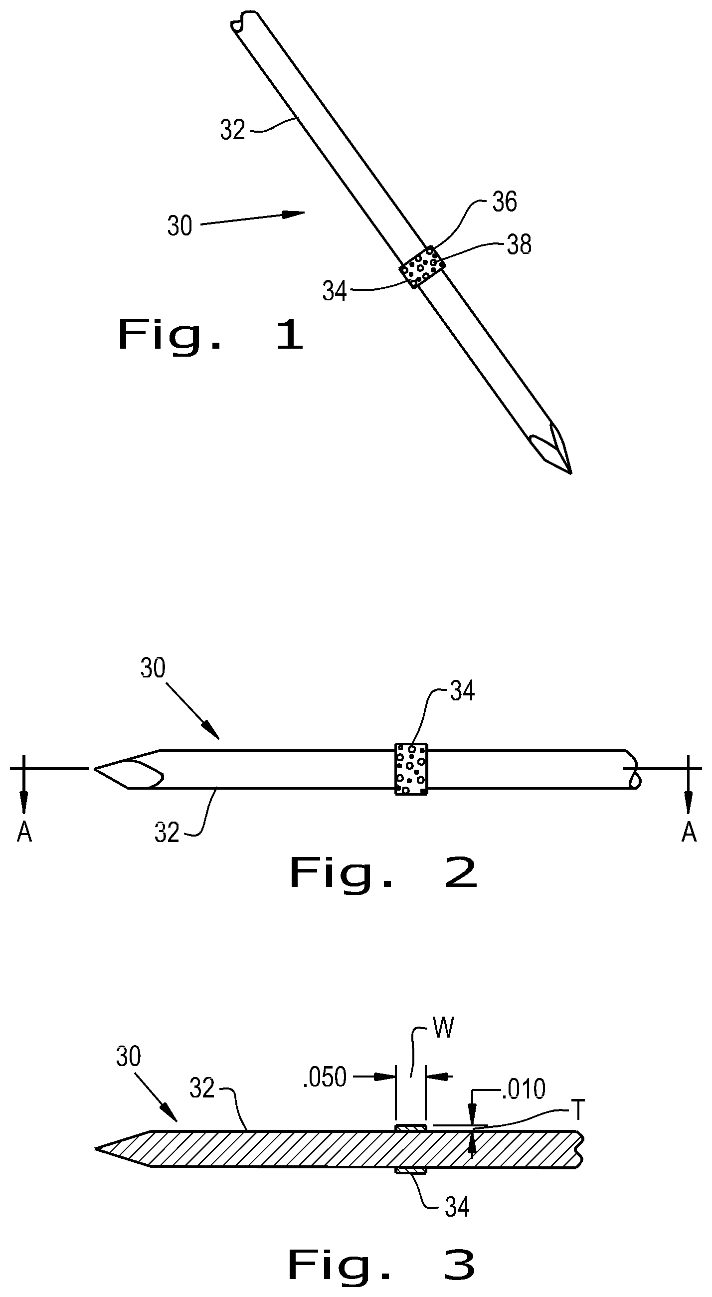
[0014] FIG. 2 is another perspective view of the orthopaedic implant shown in FIG. 1;
[0015] FIG. 3 is a cross-sectional view of the orthopaedic implant shown in FIG. 2 along line A-A;
[0016] FIG. 4 is a perspective view of another embodiment of an orthopaedic implant of the present invention;
[0017] FIG. 5 is a cross-sectional view of the orthopaedic implant shown in FIG. 4 along line A-A;
[0018] FIG. 6 is a perspective view of yet another embodiment of an orthopaedic implant of the present invention;
[0019] FIG. 7 is a sectional view of the orthopaedic implant shown in FIG. 6;
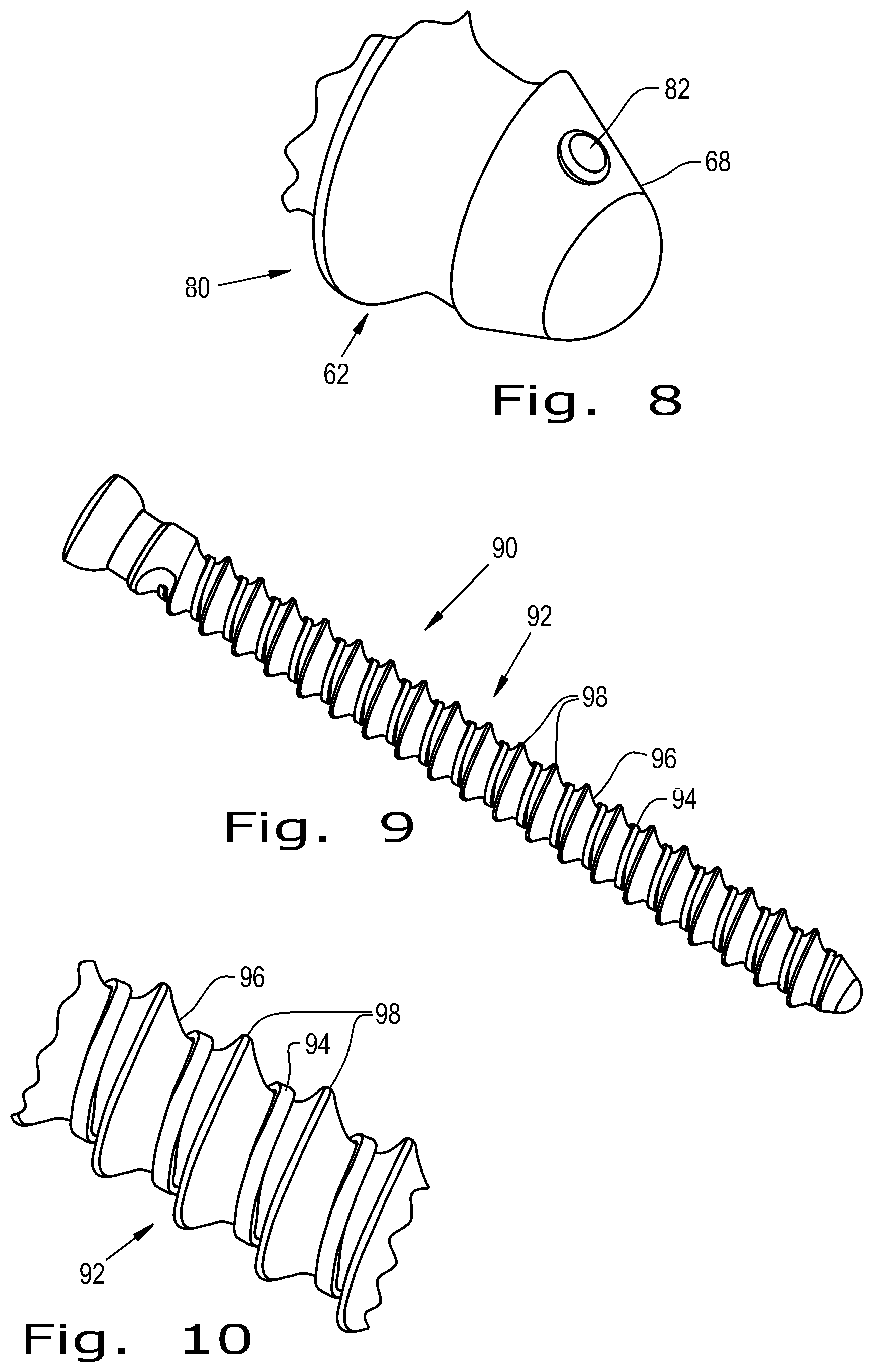
[0020] FIG. 8 is a sectional view of yet another embodiment of an orthopaedic implant of the present invention;
[0021] FIG. 9 is a perspective view of yet another embodiment of an orthopaedic implant of the present invention;
[0022] FIG. 10 is a sectional view of the orthopaedic implant shown in FIG. 9;
[0023] FIG. 11 is a perspective view of yet another embodiment of an orthopaedic implant of the present invention;
[0024] FIG. 12 is a sectional view of the orthopaedic implant shown in FIG. 11;
[0025] FIG. 13 is a perspective view of yet another embodiment of an orthopaedic implant of the present invention;
[0026] FIG. 14 is a sectional view of the orthopaedic implant shown in FIG. 13;
[0027] FIG. 15 is a perspective view of yet another embodiment of an orthopaedic implant of the present invention;
[0028] FIG. 16 is a sectional view of the orthopaedic implant shown in FIG. 15;
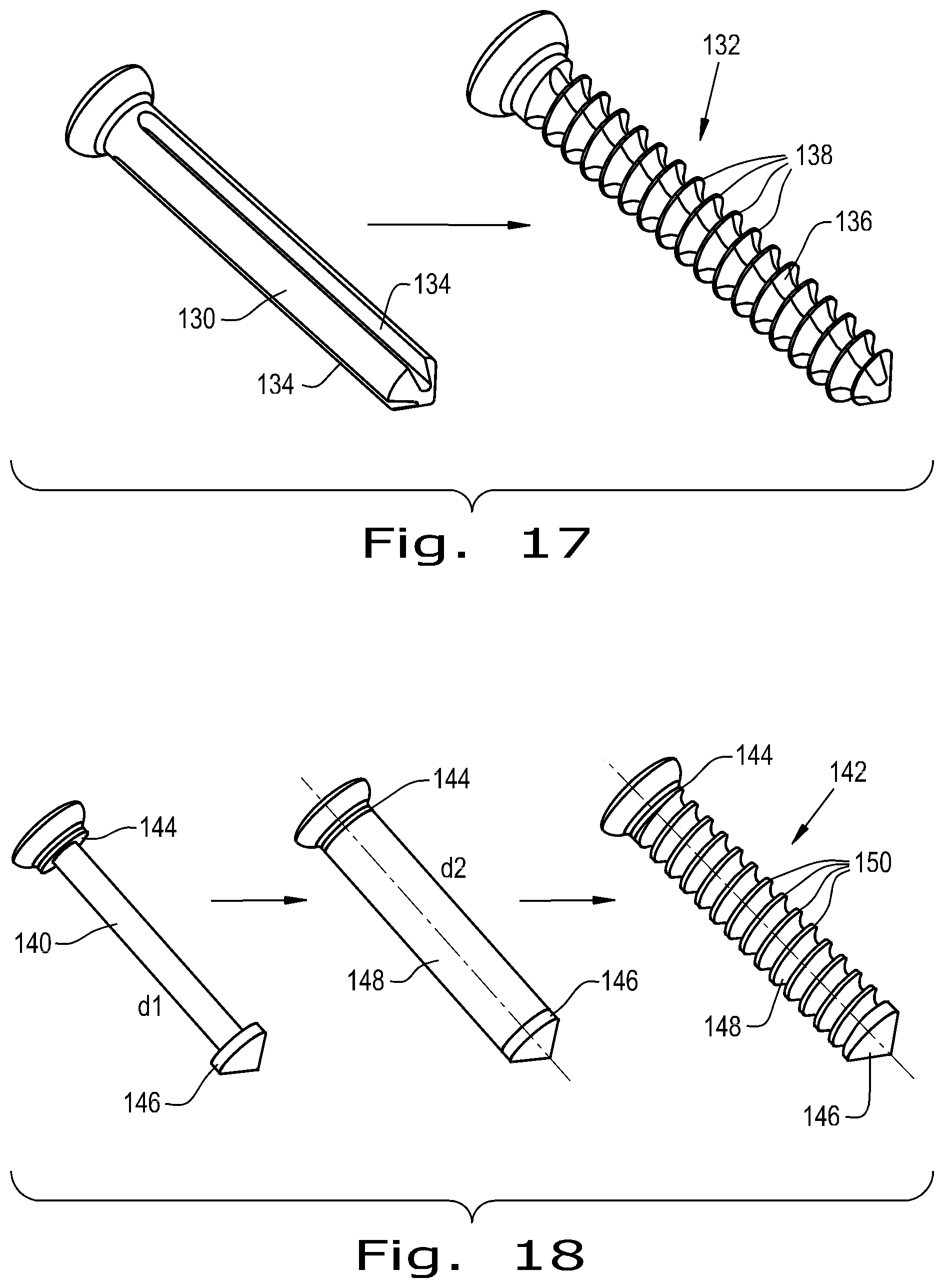
[0029] FIG. 17 is a before and after exploded view of forming yet another embodiment of an orthopaedic implant of the present invention;
[0030] FIG. 18 is another before and after exploded view of forming yet another embodiment of an orthopaedic implant of the present invention;
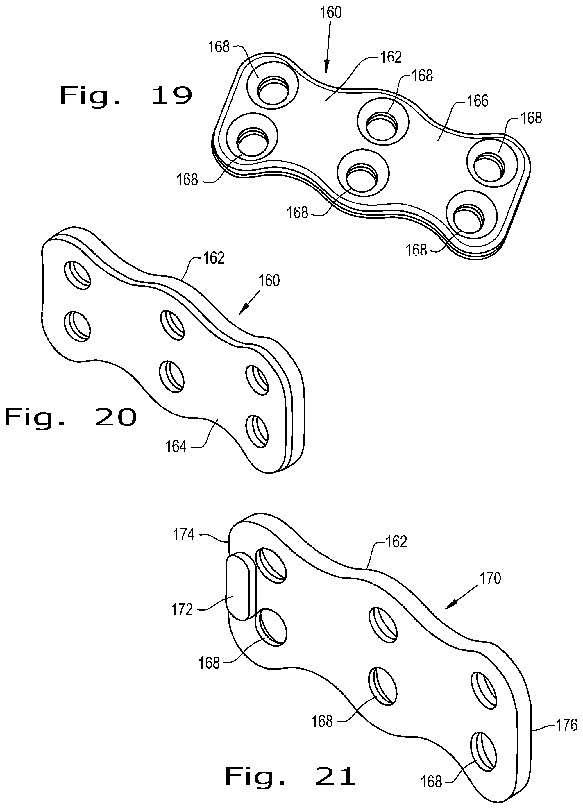
[0031] FIG. 19 is a perspective view of yet another embodiment of an orthopaedic implant of the present invention;
[0032] FIG. 20 is another perspective view of the orthopaedic implant shown in FIG. 19;
[0033] FIG. 21 is a perspective view of yet another embodiment of an orthopaedic implant of the present invention;
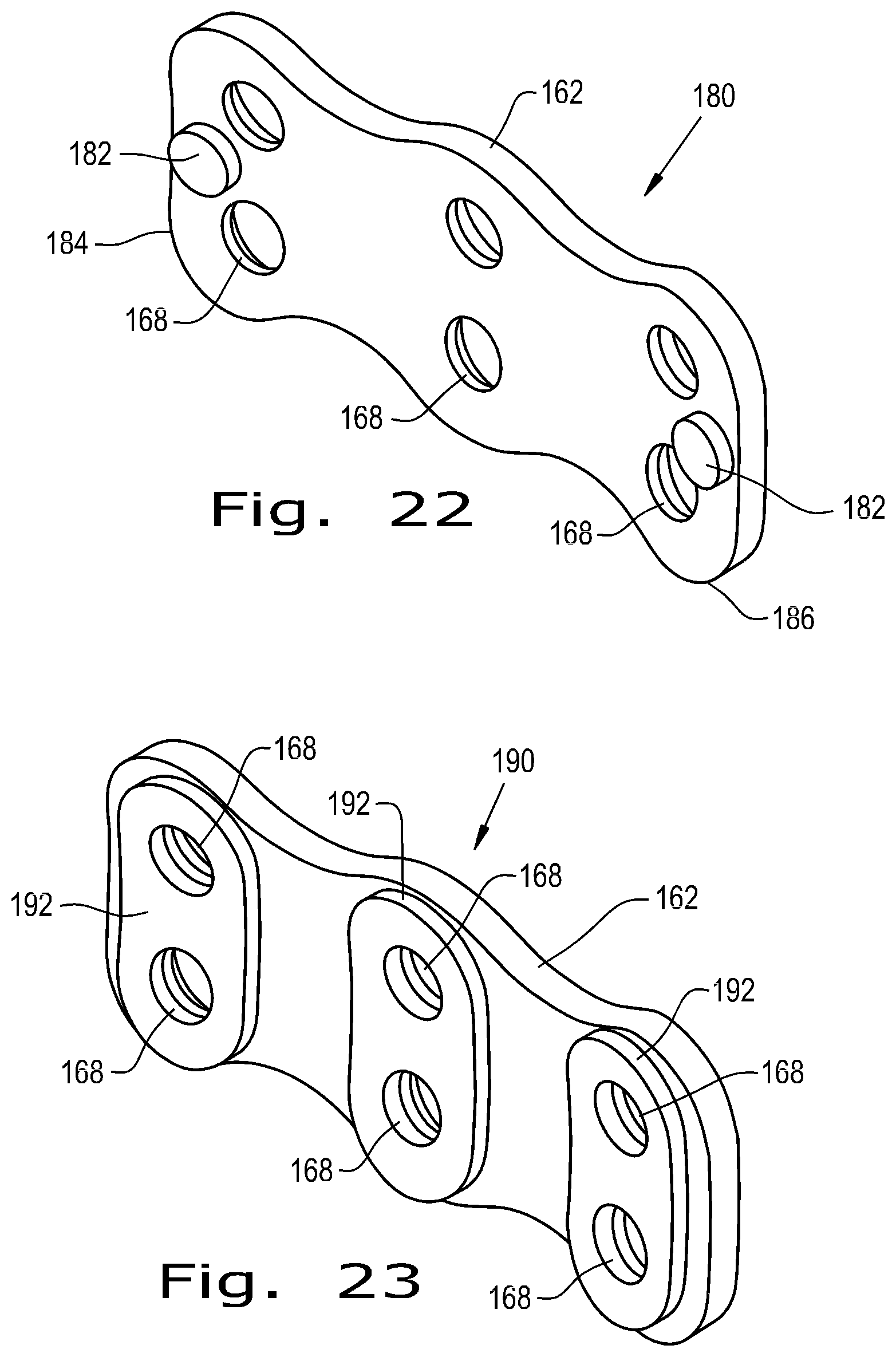
[0034] FIG. 22 is a perspective view of yet another embodiment of an orthopaedic implant of the present invention; and
[0035] FIG. 23 is a perspective view of yet another embodiment of an orthopaedic implant of the present invention.
[0036] Corresponding reference characters indicate corresponding parts throughout the several views. The exemplifications set out herein illustrate embodiments of the invention and such exemplification are not to be construed as limiting the scope of the invention in any manner.
DETAILED DESCRIPTION OF THE INVENTION
[0037] Referring now to the drawings, and more particularly to FIG. 1, there is shown an orthopaedic implant 30 which generally includes a base device 32 and a fixation material 34 attached to the base device 32. The base device 32 shown is a bone pin that can reside within a patient for a short period of time. The base device 32 can be constructed of metals commonly used in orthopaedic implants such as titanium, cobalt chrome and stainless steel. Alternatively, the base device can be constructed of biocompatible polymers such as polyether ether ketone (PEEK), polylactic acid (PLA), polyglycolic acid (PGA), polyethylene (PE) and blends thereof.
[0038] The fixation material 34 attached to the base device 32 is shaped as a thin band wrapped around the circumference of the base device 32. The fixation material 34 can be a porous polymer or metal that has a roughened surface 36 to provide immediate fixation of the device 30 due to frictional forces and to encourage quick tissue ingrowth into the fixation material 34. The roughened surface 36 can have customized surface properties for a specific tissue type and desired tissue ingrowth amount or rate. Such surface properties can include a surface energy density, wettability and electrostatic charge. Polymers and metals that can act as the fixation material 34 include PEEK, PLA, PGA, PE, titanium, cobalt chrome and stainless steel. Pores 38 of the fixation material 34 can be sized to allow or prevent ingrowth of tissue into the fixation material 34. Additionally, biologically active substances can be included in the pores 38 to encourage or limit tissue ingrowth into the fixation material 34, as well as provide other useful properties such as antimicrobial activity to reduce the risk of infection.
[0039] As the orthopaedic implant 30 is a small diameter bone pin that will likely be removed within a few weeks of implantation, a strong interface between surrounding tissue and the orthopaedic implant 30 is undesirable as it will cause removal of the orthopaedic implant 30 to be unnecessarily difficult. As can be seen in FIGS. 2 and 3, only a relatively small band of fixation material 34 is necessary to provide a minimally sufficient adhesive force that will resist pull out of the orthopaedic implant 30 while it is implanted in a patient while not causing excessive adhesive force that could make the device 30 difficult to remove. As shown in FIG. 3, the fixation material 34 has a relatively low thickness T (0.010'') and a width W ("0.050") significantly greater than the thickness T. For the orthopaedic device 30 shown, a thickness T range of about 0.005'' to 0.015'' and a width W range of about 0.020'' to 0.125'' can be appropriate dimensions for the fixation material 34 shaped as a band to provide the minimally sufficient adhesive force. It is also contemplated that there can be multiple fixation materials attached to the base device 32, which would alter the dimensions of each fixation material region. An additional design consideration when shaping and placing the fixation material 34 on a small diameter pin is that the pin won't provide much leverage to apply torque and overcome the adhesive force provided by the fixation material 34.
[0040] Referring now to FIGS. 4 and 5, an orthopaedic implant 40 is shown which includes a base device 42, shown here as a large diameter pin, with a fixation material 44 attached to the pin 42. The fixation material 44 can be the same as the fixation material 34 described previously. When utilizing a large diameter pin 42, the amount and geometry of the fixation material 44 will need to be changed to provide a minimally sufficient adhesive force that will resist natural pull out of the pin 42, due to increased size of the pin 42. As shown in FIGS. 4 and 5, the fixation material 44 can be shaped as a band around the circumference of the pin 42, similar to the previously described small diameter pin 32. The band of fixation material 44 can have a thickness T ranging from about 0.015'' to 0.050'' and a width W ranging from about 0.020'' to 0.125''. As can be seen in FIG. 5, the pin 42 can also have a groove 46 formed on the outer surface 48 of the pin 42 where the fixation material 44 attaches to the pin 42. The groove 46 can have a varying depth that changes how proud an outer surface 50 of the fixation material 44 is relative to the outer surface 48 of the pin 42. As seen in FIG. 5, the fixation material 44 has a thickness T of 0.020'', but the outer surface 50 only elevates 0.010'' relative to the outer surface 48 of the pin 42. Having the groove 46 in the pin 42 allows for a thicker fixation material 44, which will increase the potential bone ingrowth and adhesive force, with a smaller increase in the overall diameter of the device 40. The groove 46 also provides more surface area of the pin 42 to utilize for attachment to the fixation material 44. As opposed to a small diameter pin, a large diameter pin can have a larger minimally sufficient adhesive force but still be easily removed because the large diameter pin 42 provides more leverage to apply torque and overcome the adhesive force provided by the fixation material 44.
[0041] Referring now to FIGS. 6 and 7, an orthopaedic implant 60 is shown which includes a base device 62, shown as a bone screw, and a fixation material 64 attached to the bone screw 62. The bone screw 62 can be constructed of biocompatible metals and polymers, similar to previously described base devices, and the fixation material 64 can be made of a material similar to that of previously described fixation materials. The bone screw 62 has a head end 66, a distal end 68 and a plurality of threads 70 formed on a surface 72 of the bone screw 62. The fixation material 64 forms a small patch on the distal end 68 of the bone screw 62. The threads 70 of the bone screw 62 will provide some adhesive force to keep the bone screw 62 in place during implantation, so the fixation material patch 64 acts to provide additional adhesive force at the distal end 68, if necessary, to resist natural pull out of the bone screw 62.
[0042] Referring now to FIG. 8, an orthopaedic implant 80 is shown which includes a bone screw 62 similar to that shown in FIGS. 6 and 7 having a fixation material 82 attached to the distal end 68 of the bone screw 62. The fixation material 82 can be formed from any fixation material previously described. In this embodiment, the fixation material 82 is formed as a "dot" of material on the distal end 68 of the bone screw 62 to provide additional adhesive force to the bone screw 62.
[0043] Referring now to FIGS. 9 and 10, an orthopaedic implant 90 is shown which includes a bone screw 92 similar to that shown in FIGS. 6, 7 and 8 having a fixation material 94 attached to a surface 96 of the bone screw 92 between threads 98 formed on the surface 96 of the bone screw 92. The fixation material 94 can be formed from any fixation material previously described. As can be seen, the fixation material 94 has a helical shape that wraps around the circumference of the bone screw 92 between the threads 98. In this configuration, the fixation material 94 provides a substantial amount of adhesive force to resist natural pull out of the device 90. Such a configuration may be desirable for bone screws that are intended to have a longer implantation period, where additional fixation of the bone screw is desirable.
[0044] Referring now to FIGS. 11 and 12, an orthopaedic implant 100 is shown which includes a bone screw 101 similar to that shown in FIGS. 6, 7, 8 and 9 having a fixation material 102 attached near a distal end 103 of the bone screw 101 between the distal end 103 and threads 104 and 106. The fixation material 102 can be formed from any fixation material previously described. This configuration allows for the fixation material 102 to provide less fixation force than orthopaedic implant 90, previously described. Such a configuration is better suited for bone screws that are intended to have shorter implantation periods, where too much additional fixation of the bone screw would make removal unnecessarily difficult.
[0045] Referring now to FIGS. 13 and 14, an orthopaedic implant 110 is shown which includes a base device 112, shown as a bone screw, with holes 114 formed through a surface 116 of the bone screw 112 between threads 118. The holes 114 are located axially in valleys 120 between the threads 118 and go through to the centerline of the screw 112. The holes 114 can be placed along the full length of the screw 112. The screw 112 is a cannulated screw having an inner chamber 120 that has a fixation material 122 bonded inside the inner chamber 120. By having holes 114 and the fixation material 122 inside the inner chamber 120, tissue will be chemoattracted to the fixation material 122 and fill in the holes 114, forming a strong interface with the orthopaedic implant 110. A wall thickness (not shown) between the minor diameter of the bone screw 112 and the inner wall of the inner chamber 120 should be in a range of approximately 1 mm to 1.5 mm. Studies have shown that bone will bridge a gap of approximately 1 mm to 1.5 mm to grow into a porous material, such as the fixation material 122. FIGS. 15 and 16 show a similar embodiment, with fewer holes 114 formed through the bone screw 112 and the holes 114 being concentrated near a distal end 126 of the bone screw 112.
[0046] Referring now to FIG. 17, a base device 130 is shown before and after being prepared into an orthopaedic implant 132 of the present invention. As can be seen, the base device 130 is a screw blank that has had elongated pockets 134 machined within. These elongated pockets 134 are filled with a fixation material 136, which can be any fixation material previously described. Following filling of the elongated pockets 134 with the fixation material 136, threads 138 can be cut into the base device 130 and fixation material 136 to form the completed orthopaedic implant 132. In this configuration, the threads 138 will be composed of approximately half fixation material 136 and half material of the base device 130, giving the orthopaedic implant 132 a substantial amount of fixation material 136 to provide adhesive force during implantation and also placing the fixation material 136 into intimate contact with surrounding anatomy structures during implantation. Such a configuration can be particularly useful when the orthopaedic implant 132 is intended to be a long-term implant.
[0047] Referring now to FIG. 18, a base device 140 is shown before and after being prepared into an orthopaedic implant 142. The base device 140 is a screw blank with a minor diameter d1 between a head end 144 and a distal end 146. A fixation material 148, which can be any fixation material previously described, is bonded to a section of the base device 140 having minor diameter d1 to create a diameter d2 similar to that of the head end 146 and distal end 148. Threads 150 are then formed into the fixation material 148 to create the completed orthopaedic implant 142.
[0048] Referring now to FIGS. 19 and 20, an orthopaedic implant 160 is shown that includes a base device 162, shown as a bone plate, and a fixation material 164 attached to the bone plate 162. The bone plate 162 has a bare surface 166 and multiple openings 168 that are sized to allow bone screws (not shown) to be passed through. The openings 168 are shaped so that when the bone screws are driven into a bone, they will hold the bone plate 162 in place. The bone plate 162 can be made of biocompatible metals such as titanium, cobalt chrome and stainless steel, but can also be made of a biocompatible polymer such as PEEK. A polymer bone plate 162 could offer advantages over more common metal bone plates, such as higher compression and adjustable stiffening. The fixation material 164 is attached to a bottom surface (not shown) that is opposed to the bare surface 166 and will be in contact with the bone during implantation. The fixation material 164 can be any fixation material previously described. In this embodiment, the fixation material 164 forms a layer on the bottom surface of the bone plate 162. Since bone screws will be going through the openings 168, the fixation material 164 does not cover the openings 168. If the bone plate 162 had a bare bottom surface, the only fixation that the bone plate 162 would have when implanted would be provided by friction from the bone screws implanted in the bone. By attaching the fixation material 164 to the bottom surface of the bone plate 162, the bone plate 162 is provided with adhesive force of its own: initially from the roughness of the fixation material and later from bone ingrowth into the fixation material 164. Although the fixation material 164 is shown covering the entire bottom surface of the bone plate 162, the amount of fixation material 164 could be altered to provide a desired amount of adhesive force to the bone plate.
[0049] Referring now to FIG. 21, an orthopaedic implant 170 is shown that includes the bone plate 162 of FIGS. 19 and 20 with a fixation material 172 attached at one end 174 of the bone plate 162. The fixation material 172 is shaped as a patch and can be any fixation material previously described. By attaching the fixation material 172 to only one end 174 of the bone plate 162, bone ingrowth and fixation will only occur at the end 174 of the plate with the fixation material 172, allowing an opposite end 176 to float to whatever degree the attached bone screws allow. Such a configuration allows for a dynamic bone plate 170.
[0050] Referring now to FIG. 22, an orthopaedic implant 180 is shown that includes the bone plate 162 of FIGS. 19, 20 and 21 with two regions of a fixation material 182 attached at both ends 184, 186 of the bone plate 162. The regions of fixation material 182 are shaped as dots of material and can be any fixation material previously described. Attaching the fixation material 182 to both ends 184, 186 of the bone plate 162 provides bone ingrowth, and therefore fixation, at both ends 184, 186 of the bone plate 162.
[0051] Referring now to FIG. 23, an orthopaedic implant 190 is shown that includes the bone plate 162 of FIGS. 19, 20, 21 and 22 with three regions of a fixation material 192 surrounding the openings 168 of the bone plate 162. The fixation material 192 can be any fixation material previously described. Bone ingrowth into the fixation material 192 around the openings 168 provide additional fixation to the bone plate 162 in those regions. Such a configuration could be desirable if the bone screws are to be removed after implantation or do not provide enough fixation of the bone plate 162 on their own.
[0052] While this invention has been described with respect to at least one embodiment, the present invention can be further modified within the spirit and scope of this disclosure. This application is therefore intended to cover any variations, uses, or adaptations of the invention using its general principles. Further, this application is intended to cover such departures from the present disclosure as come within known or customary practice in the art to which this invention pertains and which fall within the limits of the appended claims.
* * * * *
D00000
D00001
D00002
D00003
D00004
D00005
D00006
D00007
D00008
XML
uspto.report is an independent third-party trademark research tool that is not affiliated, endorsed, or sponsored by the United States Patent and Trademark Office (USPTO) or any other governmental organization. The information provided by uspto.report is based on publicly available data at the time of writing and is intended for informational purposes only.
While we strive to provide accurate and up-to-date information, we do not guarantee the accuracy, completeness, reliability, or suitability of the information displayed on this site. The use of this site is at your own risk. Any reliance you place on such information is therefore strictly at your own risk.
All official trademark data, including owner information, should be verified by visiting the official USPTO website at www.uspto.gov. This site is not intended to replace professional legal advice and should not be used as a substitute for consulting with a legal professional who is knowledgeable about trademark law.