Modular Augment Component
Kehres; Clinton E.
U.S. patent application number 16/475215 was filed with the patent office on 2019-11-07 for modular augment component. The applicant listed for this patent is Biomet Manufacturing, LLC. Invention is credited to Clinton E. Kehres.
| Application Number | 20190336293 16/475215 |
| Document ID | / |
| Family ID | 62909268 |
| Filed Date | 2019-11-07 |
| United States Patent Application | 20190336293 |
| Kind Code | A1 |
| Kehres; Clinton E. | November 7, 2019 |
MODULAR AUGMENT COMPONENT
Abstract
Disclosed is a central augment. The central augment can include a body and a protrusion. The body can include a first curved surface shaped to interface with a central portion of a bone and a second surface opposite the first curved surface and defining a recess sized to receive a portion of a prosthetic component. The protrusion can extend from the second surface within the recess.
| Inventors: | Kehres; Clinton E.; (Warsaw, IN) | ||||||||||
| Applicant: |
|
||||||||||
|---|---|---|---|---|---|---|---|---|---|---|---|
| Family ID: | 62909268 | ||||||||||
| Appl. No.: | 16/475215 | ||||||||||
| Filed: | January 16, 2018 | ||||||||||
| PCT Filed: | January 16, 2018 | ||||||||||
| PCT NO: | PCT/US2018/013795 | ||||||||||
| 371 Date: | July 1, 2019 |
Related U.S. Patent Documents
| Application Number | Filing Date | Patent Number | ||
|---|---|---|---|---|
| 62448547 | Jan 20, 2017 | |||
| Current U.S. Class: | 1/1 |
| Current CPC Class: | A61F 2002/30736 20130101; A61F 2002/30881 20130101; A61F 2002/3092 20130101; A61F 2/30734 20130101; A61F 2/40 20130101; A61F 2/4081 20130101; A61F 2002/30878 20130101; A61F 2/30 20130101 |
| International Class: | A61F 2/30 20060101 A61F002/30; A61F 2/40 20060101 A61F002/40 |
Claims
1. A central augment for use in a shoulder replacement procedure, the central augment comprising: a body including a glenoid engagement surface shaped to interface with a central portion of a reamed glenoid and a second surface opposite the first curved surface and defining a recess sized to receive a boss of a glenoid component; a protrusion extending from the second surface within the recess, the protrusion sized to be received within a bore defined by the boss of the glenoid component; and a post extending from the glenoid engagement surface, the post sized to be received in a bore formed in the central portion of the glenoid, wherein at least one of the body and the post includes a porous metal coating.
2. The central augment of claim 1, wherein the first curved surface has a bulbous shape.
3. The central augment of claim I ,wherein the first curved surface has a spherical shape.
4. The central augment of claim 1, wherein the first curved surface is shaped for a specific patient.
5. The central augment of claim 1, wherein the post includes a threaded portion.
6. The central augment of claim 1, wherein the post includes a barbed portion.
7. The central augment of claim 1, wherein the post is a fluted peg.
8. The central augment of claim 1, wherein the recess includes a tapered profile complementary to the portion of the glenoid component.
9. The central augment of claim 1, wherein the protrusion includes one or more external threads configured to mate with one or more internal threads disposed within the boss of the glenoid component.
10. The central augment of claim 1, wherein at least one of the body and the post includes a porous metal coating.
11. A modular glenoid system for use in a shoulder replacement procedure, the modular glenoid system comprising: a glenoid component including: an articulation surface, a glenoid engaging surface opposite the articulation surface, and a boss extending from the glenoid engaging surface; and a modular augment including: a first outer surface, a second internal surface opposite the first outer surface and defining a recess sized to receive the boss. a post, the first outer surface forming a dome and shaped to interface with a reamed portion of a glenoid, the post extending from the first outer surface and sized to be received in a bore created in the glenoid; and a protrusion extending from the second internal surface and sized to be received within a bore in the boss.
12. . The modular glenoid system of claim 11, Wherein the protrusion includes a male threaded portion and the bore includes a female threaded portion for receiving the male threaded portion.
13. The modular glenoid system of claim 11, wherein the glenoid component includes a plurality of pegs spaced about the boss.
14. The modular glenoid system of claim 11, wherein the modular augment is selected from a plurality of modular augments, each of the plurality of modular augments sized to complement a different sized central defect.
15. A method for replacing a glenoid component, the method comprising: reaming a central portion of a glenoid; implanting a modular augment into the central portion of the glenoid, the modular augment including a first curved surface, a second curved surface opposite the first curved surface and defining a recess sized to receive a boss extending from an augment engaging surface of a glenoid component, the first curved surface including a post extending therefrom sized to be received in a bore created in the boss of the glenoid component; and implanting the glenoid component into the glenoid, the glenoid component coupled to the modular augment via the post and the bore created in the boss.
16. The method of claim 15, further comprising selecting the modular augment from a plurality of modular augments, each of the plurality of modular augments sized to complement a different sized central defect.
17. The method of claim 15, wherein the modular augment is patient specific.
18. The method of any claim 15, wherein implanting the modular augment and the glenoid component occur simultaneously.
19. The method of claim 18, further comprising screwing the post into the bore of the boss of the glenoid component.
20. The method of claim 15, wherein the modular augment is press fitted with the glenoid component.
Description
PRIORITY CLAIM
[0001] This application claims priority to U.S. Provisional Application No. 62/448,547, filed on Jan. 20, 2017, the content of which are hereby incorporated by reference in its entirety,
FIELD OF THE DISCLOSURE
[0002] The present disclosure relates to surgical implant systems, including implants, instruments, and methods for installing an implant. Specifically, the present disclosure relates to systems and methods for securing a glenoid implant to a glenoid.
BACKGROUND
[0003] Surgical procedures for repairing or reconstructing a joint can require securely fastening a surgical implant to a hone. For example, shoulder joint reconstruction can require fixing a glenoid implant to a scapula to reproduce or replicate a glenoid cavity on the scapula. The surgical implant can be securely fastened to the hone in a variety of ways, including mechanical fasteners and adhesive.
SUMMARY
[0004] To better illustrate the system disclosed herein, a non-limiting list of examples is provided here:
[0005] Example 1 is a central augment for use in a shoulder replacement procedure, the central augment comprising: a body including a glenoid engagement surface shaped to interface with a central portion of a reamed glenoid and a second surface opposite the first curved surface and defining a recess sized to receive a boss of a glenoid component; a protrusion extending from the second surface within the recess, the protrusion sized to be received within a bore defined by the boss of the glenoid component; and a post extending from the glenoid engagement surface, the post sized to be received in a bore formed in the central portion of the glenoid, wherein at least one of the body and the post includes a porous metal coating.
[0006] In Example 2, the subject matter of Example 1 optionally includes wherein the first curved surface has a bulbous shape.
[0007] In Example 3, the subject matter of any one or more of Examples 1-2 optionally include wherein the first curved surface has a spherical shape.
[0008] In Example 4, the subject matter of any one or more of Examples 1-3 optionally include wherein the first curved surface is shaped for a specific patient.
[0009] In Example 5, the subject matter of any one or more of Examples 1-4 optionally include wherein the post includes a threaded portion.
[0010] In Example 6, the subject matter of any one or more of Examples 1-5 optionally include wherein the post includes a barbed portion.
[0011] In Example 7, the subject matter of any one or more of Examples 1-6 optionally include wherein the post is a fluted peg.
[0012] In Example 8, the subject matter of any one or more of Examples 1-7 optionally include wherein the recess includes a tapered profile complementary to the portion of the glenoid component.
[0013] In Example 9, the subject matter of any one or more of Examples 1-8 optionally include wherein the protrusion includes one or more external threads configured to mate with one or more internal threads disposed within the boss of the glenoid component.
[0014] In Example 10, the subject matter of any one or more of Examples 1-9 optionally include wherein at least one of the body and the post includes a porous metal coating.
[0015] Example 11 is a modular glenoid system for use in a shoulder replacement procedure, the modular glenoid system comprising: a glenoid component including: an articulation surface, a glenoid engaging surface opposite the articulation surface, and a boss extending from the glenoid engaging surface; and a modular augment including: a first outer surface, a second internal surface opposite the first outer surface and defining a recess sized to receive the boss, a post, the first outer surface forming a dome and shaped to interface with a reamed portion of a glenoid, the post extending from the first outer surface and sized to be received in a bore created in the glenoid; and a protrusion extending from the second internal surface and sized to be received within a bore in the boss.
[0016] In Example 12, the subject matter of Example 11 optionally includes wherein the protrusion includes a male threaded portion and the bore includes a female threaded portion for receiving the male threaded portion.
[0017] In Example 13, the subject matter of any one or more of Examples 11-12 optionally include wherein the glenoid component includes a plurality of pegs spaced about the boss.
[0018] In Example 14, the subject matter of any one or more of Examples 11-13 optionally include wherein the modular augment is selected from a plurality of modular augments, each of the plurality of modular augments sized to complement a different sized central defect.
[0019] Example 15 is a method for replacing a glenoid component, the method comprising: reaming a central portion of a glenoid; implanting a modular augment into the central portion of the glenoid, the modular augment including a first curved surface, a second curved surface opposite the first curved surface and defining a recess sized to receive a boss extending from an augment engaging surface of a glenoid component, the first curved surface including a post extending therefrom sized to be received in a bore created in the boss of the glenoid component; and implanting the glenoid component into the glenoid, the glenoid component coupled to the modular augment via the post and the bore created in the boss.
[0020] In Example 16, the subject matter of Example 15 optionally includes selecting the modular augment from a plurality of modular augments, each of the plurality of modular augments sized to complement a different sized central defect.
[0021] In Example 17, the subject matter of any one or more of Examples 15-16 optionally include wherein the modular augment is patient specific.
[0022] In Example 18, the subject matter of any one or more of Examples 15-17 optionally include wherein implanting the modular augment and the glenoid component occur simultaneously.
[0023] In Example 19, the subject matter of Example 18 optionally includes screwing the post into the bore of the boss of the glenoid component.
[0024] In Example 20, the subject matter of any one or more of Examples 15-19 optionally include wherein the modular augment is press fitted with the glenoid component.
[0025] In Example 21, the modular augment or modular glenoid system of any one of or any combination of Examples 1-20 is optionally configured such that all elements or options recited are available to use or select from.
BRIEF DESCRIPTION OF THE FIGURES
[0026] The above-mentioned and other features and advantages of this disclosure, and the manner of attaining them, will become more apparent and the disclosure itself will be better understood by reference to the following description of embodiments taken in conjunction with the accompanying drawings, wherein:
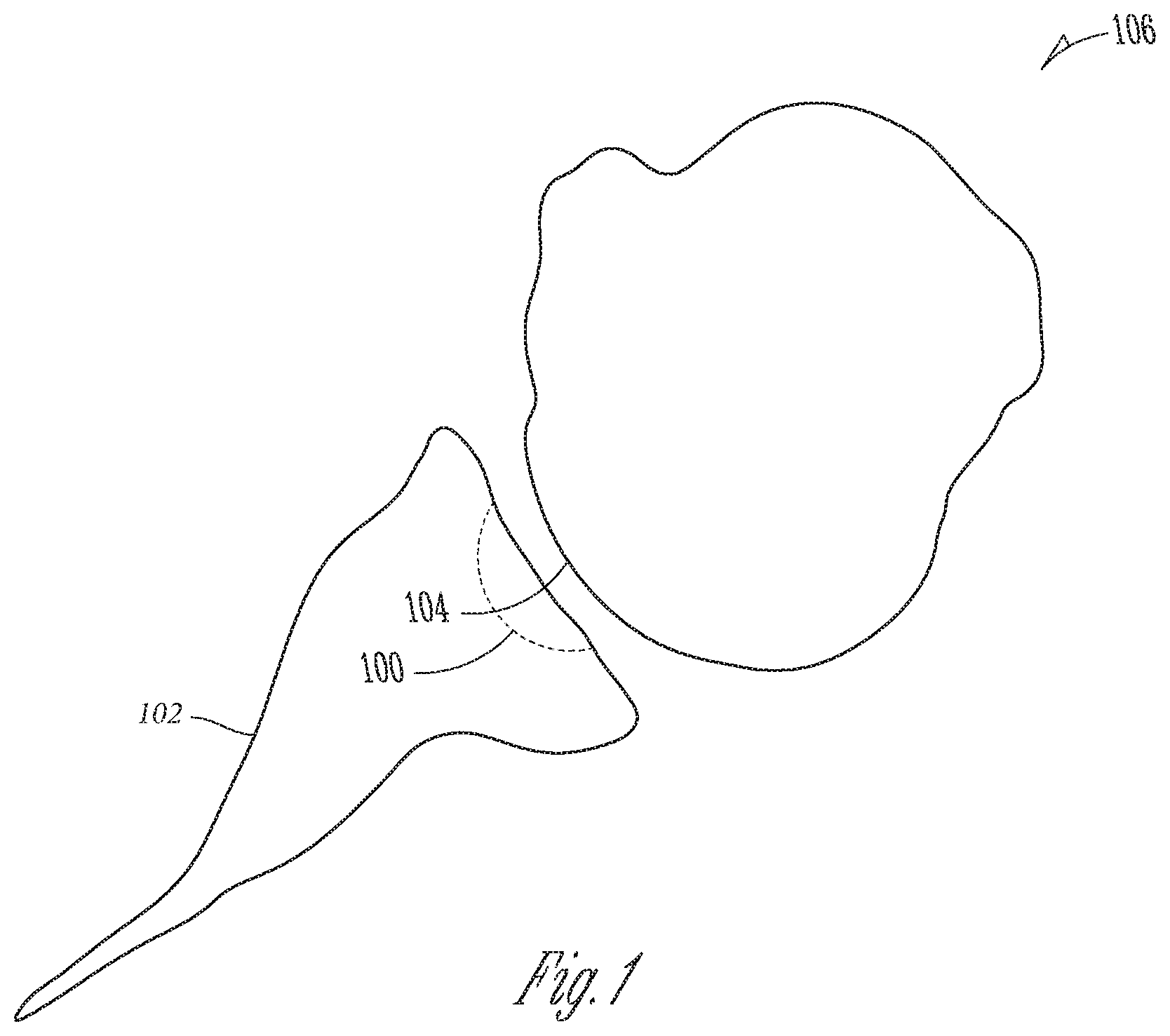
[0027] FIG. 1 shows a central defect in a glenoid.
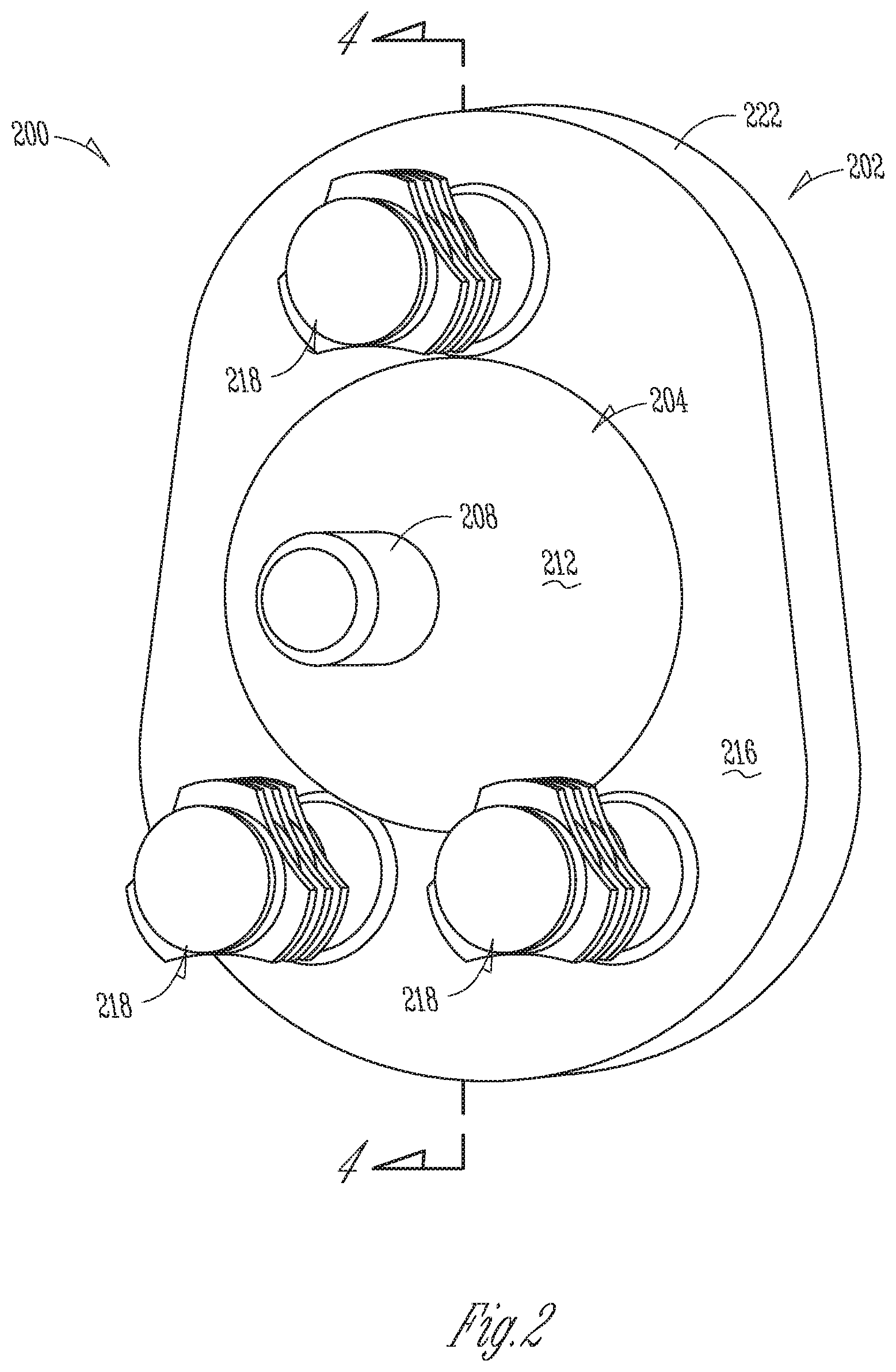
[0028] FIG. 2 shows a perspective view of a modular glenoid system in accordance with at least one example of the present disclosure.
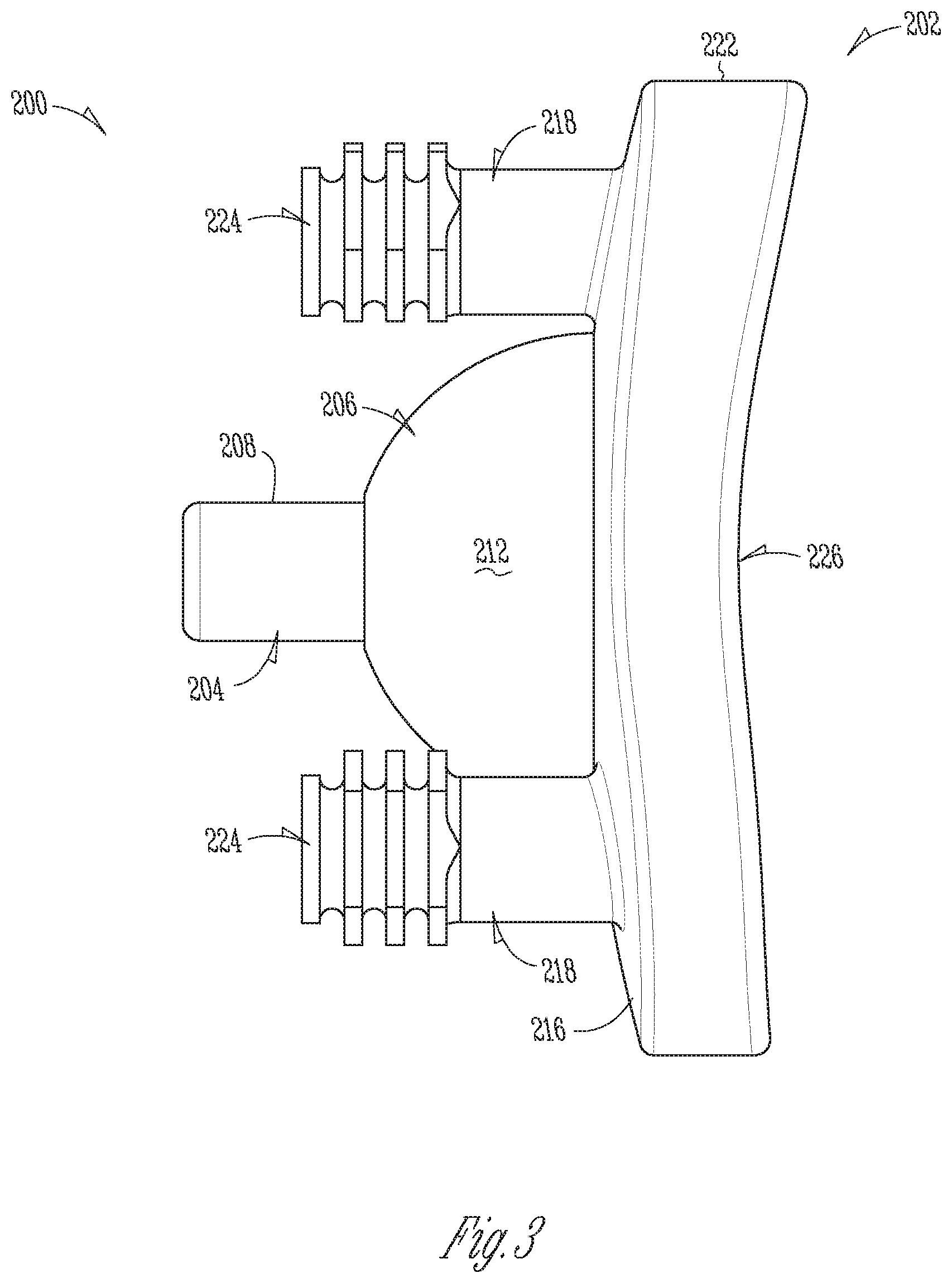
[0029] FIG. 3 shows a side view of a modular glenoid system in accordance with at least one example of the present disclosure.
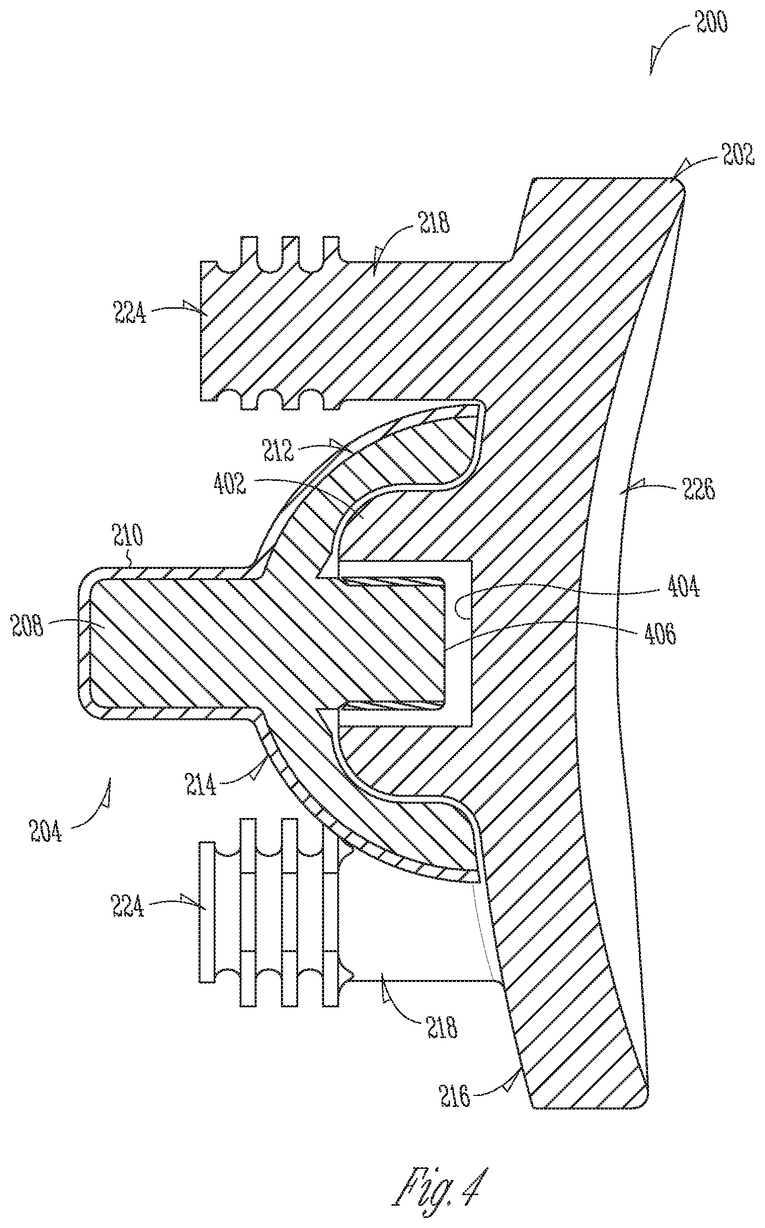
[0030] FIG. 4 shows a section view of a modular glenoid system in accordance with at least one example of the present disclosure.
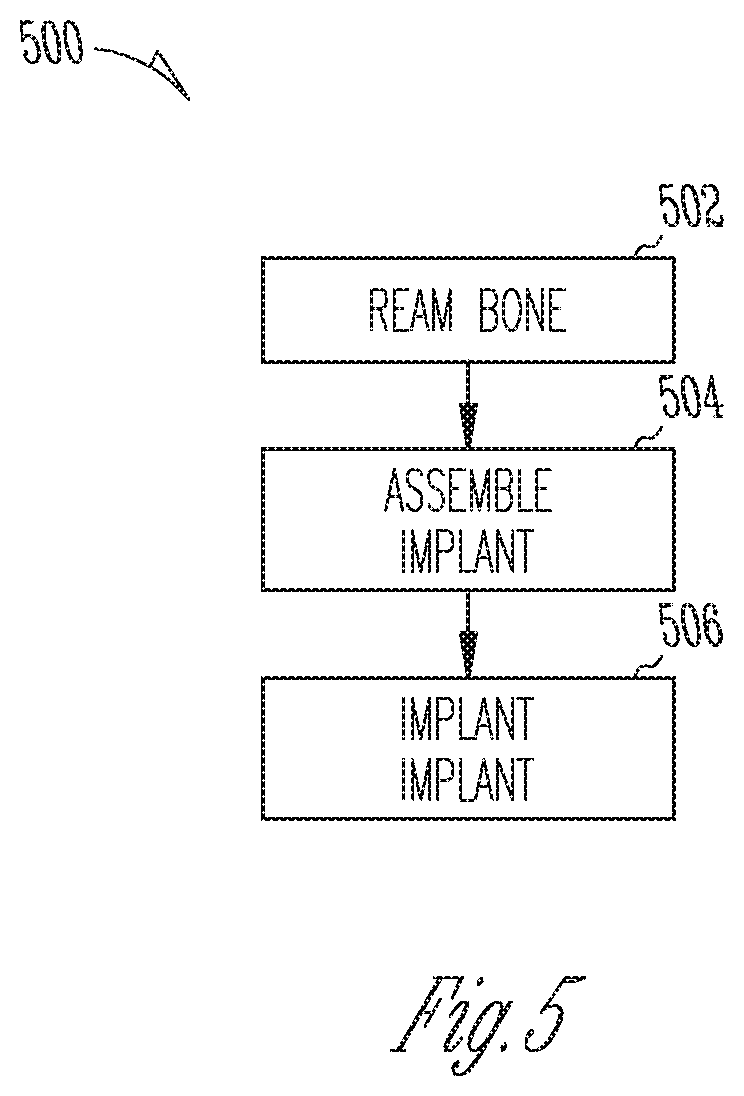
[0031] FIG. 5 shows an example method for a glenoid arthroplasty in accordance with at least one example of the present disclosure.
[0032] Corresponding reference characters indicate corresponding parts throughout the several views. The exemplifications set out herein illustrate exemplary embodiments of the disclosure, and such exemplifications are not to be construed as limiting the scope of the disclosure any manner.
DETAILED DESCRIPTION
[0033] As used herein, the following directional definitions apply. Anterior and posterior mean nearer the front or nearer the rear of the body, respectively, proximal and distal mean nearer to or further from the root of a structure, respectively, and medial and lateral mean nearer the sagittal plane or further from the sagittal plane, respectively. The sagittal plane is an imaginary vertical plane through the middle of the body that divides the body into right and left halves. In addition, the terms implant and prosthesis, and variations thereof, can be used interchangeably.
[0034] Through injury, trauma, aging, or other degenerative conditions a joint, such as the shoulder, can become damaged or otherwise less mobile. In addition, the injury, trauma, aging, or other condition can cause repeated injury. For example, an injury to a shoulder can cause a central defect or other damage to a glenoid socket. The central defect or other damage can cause the humeral head to more easily become dislocated from the glenoid socket. For instance, a person can suffer from a glenoid chondral defect that can lead to or be caused by glenohumeral dislocation.
[0035] As disclosed herein, a modular augment can be used to repair a central defect. The modular augment can include a body and a post that extends from the body. The post and body portions can be implanted into a central portion of a glenoid socket to assist in repairing a central defect. Addressing a central defect with the modular augment can allow for existing bone around a central portion of the glenoid to be saved or otherwise remain undisturbed during a surgical procedure.
[0036] The central defect can be in any bony anatomy. For example, the central defect can be in a shoulder joint, a hip joint, or the hand or wrist. For instance, in a shoulder joint the central defect can be in the glenoid. In a hip joint the central defect can be in an acetabular fossa. In a hand, the central defect can be in a base of a metacarpal bone or phalanges bones.
[0037] FIG. 1 shows a central defect 100 in a bone 102. The bone 102 can be a glenoid, acetabular fossa, etc. The central defect 100 can be a bare spot or other central area of cartilage loss on a fossa (such as a glenoid fossa) with or without underlying bone damage. Other types of central defects can include, but are not limited to, cartilage lesions of the glenohumeral joint such as Hill-Sachs lesions or articular cartilage lesions. As shown in FIG. 1, the central defect 100 can affect the way a bone surface 104 (such as a humeral surface) of a head portion 106 (such as a humeral head) interacts with the bone 102.
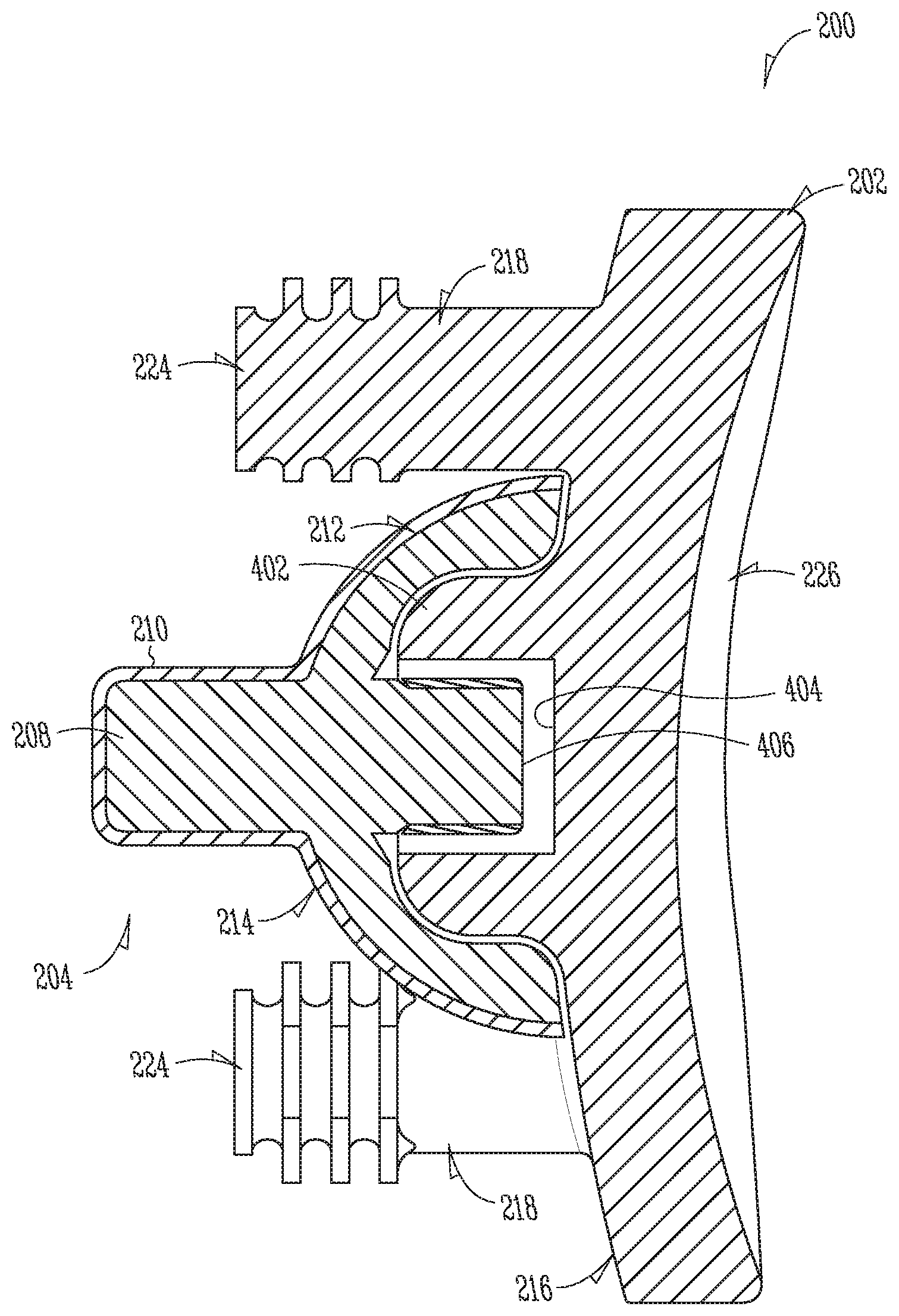
[0038] With reference to FIGS. 2-4, a modular glenoid system 200 in accordance with some aspects of the present disclosure is illustrated. The modular glenoid system 200 can include a glenoid component 202 and a modular augment 204. As disclosed herein, the modular augment 204 can be inserted into a glenoid (such as bone 102), with minimal resecting of the glenoid. For example, a central portion of the glenoid can be reamed or otherwise prepared to receive the modular augment 204 while the infraglenoid tubercle or other portions of the glenoid cavity or scapular can remain in a natural or otherwise undisturbed state. While FIGS. 2-4 show a system described with respect to a glenoid and in an anatomical configuration, the systems and methods disclosed herein can be apply in reverse procedures such as a revers shoulder arthroplasty, in other joints such as the hip joint, etc.
[0039] The modular augment 204 can include a body 206 and a post 208 that extends from the body 206. As shown in FIG. 4, the body 206 and the post 208 can include a porous metal layer 210 on at least a portion thereof. In addition, and in various examples, only the post 208 can include the porous metal layer 210. Furthermore, and in various examples, only the body 206 can include the porous metal layer 210. Moreover, in various examples, the post 208 and/or the body 206 can be formed as a porous component instead of having a porous layer formed thereon.
[0040] The porous metal layer 210 (or porous components) can allow for bone ingrowth to further secure the modular augment 204 to the glenoid. The porous metal layer 210 can be a highly porous, three-dimensional metallic structure that can incorporate one or more of a variety of biocompatible metals such as but not limited to titanium, a titanium alloy, cobalt chromium, cobalt chromium molybdenum, tantalum, a tantalum alloy, niobium, or alloys of tantalum and niobium with one another or with other metals. Such structures are particularly suited for contacting bone and/or soft tissue, and in this regard, can be useful as bone substitutes and other implants and implant components that are receptive to cell and tissue ingrowth, for example, by allowing bony tissue or other tissue to grow into the porous structure over time to enhance fixation (e.g., osseointegration) between the structure and surrounding bodily structures. In accordance with examples disclosed herein, an open porous metal structure, or a portion thereof, can have a bulk porosity as low as 55%, 65%, or 75% or as high as 80%, 85%, or 90%, or within any range defined between any pair of the foregoing values, and in this regard, such structures can provide lightweight, yet strong porous implants. Certain porous metal structures, despite having such high porosities, are capable of withstanding extreme mechanical loads at the time of implantation and over long periods of time, for example, where a highly porous, three-dimensional metallic structure is forcefully impacted and press fit into a bone, by itself or connected to another implant, and maintains its shape during impaction and following many months or years of service in the body. Such structures can be manufactured according to any suitable technique or process. An example of an open porous metal structure is produced using Trabecular Metal.RTM. Technology available from Zimmer, Inc., of Warsaw, Ind. Trabecular Metal.RTM. is a trademark of Zimmer, Inc. Such a material can be formed from a reticulated vitreous carbon foam substrate which is infiltrated and coated with a biocompatible metal, such as tantalum, by a chemical vapor deposition ("CVD") process in the manner disclosed in detail in U.S. Pat. No. 5,282,861 and in Levine, B. R., et al., "Experimental and Clinical Performance of Porous Tantalum in Orthopedic Surgery", Biomaterials 27 (2006) 4671-4681, the disclosures of which are expressly incorporated herein by reference.
[0041] In some instances, a highly porous, three-dimensional metallic structure can be fabricated using a selective laser sintering (SLS) or other additive manufacturing-type process such as direct metal laser sintering or electron beam melting. In one example, a three-dimensional porous article can be produced in layer-wise fashion from a laser-fusible powder, e.g., a single-component metal powder, which can be deposited one layer at a time. The powder can be fused, remelted or sintered, by the application of laser energy that is directed to portions of the powder layer corresponding to a cross section of the article. After the fusing of the powder in each layer, an additional layer of powder can be deposited, and a further fusing step can be carried out, with fused portions or lateral layers fusing so as to fuse portions of previous laid layers until a three-dimensional article is complete. In certain examples, a laser can selectively fuse powdered material by scanning cross-sections generated from a 3-D digital description of the article, e.g., from a CAD file or scan data, on the surface of a powder bed. Complex geometries can be created using such techniques, and in some instances, net shape and near net shape implants can be constructed. In some examples, a non-porous or essentially non-porous base substrate can provide a foundation upon which a three-dimensional porous structure can be built and fused thereto using a selective laser sintering (SLS) or other additive manufacturing-type process. Such substrates can incorporate one or more of a variety of biocompatible metals such as any of those disclosed herein.
[0042] Generally, a highly porous, three-dimensional metallic structure will include a large plurality of ligaments that define open voids (e.g., pores) or channels between the ligaments. The open spaces between the ligaments form a matrix of continuous channels having few or no dead ends, such that growth of soft tissue and/or bone through the open porous metal is substantially uninhibited. According to some aspects of the present disclosure, exterior surfaces of an open porous metal structure can feature terminating ends of the above-described ligaments. Such terminating ends can be referred to as struts, and they can generate a high coefficient of friction along an exposed porous metal surface. Such features can impart an enhanced affixation ability to an exposed porous metal surface for adhering to bone and soft tissue. Also, when such highly porous metal structures are coupled to an underlying substrate, a small percentage of the substrate can be in direct contact with the ligaments of the highly porous structure, for example, approximately 15%, 20%, or 25%, of the surface area of the substrate can be in direct contact with the ligaments of the highly porous structure.
[0043] A highly porous, three-dimensional metallic structure can be fabricated such that it comprises a variety of densities in order to selectively tailor the structure for particular orthopedic applications, for example, by matching the structure to surrounding natural tissue in order to provide an improved matrix for tissue ingrowth and mineralization. Such structures can be isotropic or anisotropic. In this regard, according to certain examples, an open porous metal structure can be fabricated to have a substantially uniform porosity, density, void (pore) size, pore shape, and/or pore orientation throughout, or to have one or more features such as porosity, density, void (pore) size, pore shape, and/or pore orientation being varied within the structure, or within a portion thereof. For example, an open porous metal structure can have a different pore size, pore shape, and/or porosity at different regions, layers, and surfaces of the structure. The ability to selectively tailor the structural properties of the open porous metal enables, for example, tailoring of the structure for distributing stress loads throughout the surrounding tissue and promoting specific tissue ingrowth within the open porous metal. In some instances, a highly porous, three-dimensional metallic structure, once formed, can be infiltrated and coated with one or more coating materials such as biocompatible metals such as any of those disclosed herein.
[0044] In addition to a porous metal, the post 208 or the porous metal layer 210 can form threads, barbs, or other protrusions that can allow the modular augment 204 to be screwed into or otherwise secured to the glenoid. Furthermore, the post 208 can be tapered and can include one or more flutes, fins, ribs, or other projections extending therefrom. The threads, barbs, flutes, fins, ribs, or other protrusions can provide surfaces for bone contact and can create anchoring structures to help secure the modular augment 204. For instance, during recovery, bone can grow in between the threads, barbs, flutes, fins, ribs, or other protrusions to assist in securing the module augment 204 to the glenoid.
[0045] The body 206 can include a curved surface 212 and a glenoid component engaging surface 214. The curved surface 212 can match a profile of a reamed portion of the glenoid. For example, a reamer can have a hemispherical profile or other bulbous shape that corresponds to a hemispherical or bulbous shape of the curved surface 212. In addition, the curved surface 212 can be patient specific. For instance, a surgeon can use images of a patient's glenoid and specify a shape of the curved surface 212 to match the anatomy of the patient. The modular augment 204 can then be manufactured with the curved surface 212 matched to the specific contours (reamed or natural) for a particular patient.
[0046] The glenoid component engaging surface 214 can match a profile of the glenoid component 202. For example, the glenoid component 202 can include a boss 402 that projects from a glenoid engaging surface 216. Stated another way, the glenoid component engaging surface 214 can define a recess sized to receive a portion of the glenoid component 202 (e.g., the boss 402) or, as shown in FIG. 4, an entirety of the glenoid component 202 (e.g., the boss 402), and extend around the glenoid component 202 in a dome-like manner. The boss 402 can be centrally located as shown in FIG. 2 or offset as needed for a patient. The glenoid component engaging surface 214 can allow the modular augment 204 to engage the glenoid component 202 via any suitable connection, such as a threaded connection, a snap fit connection, or a press fit connection. The boss 402 can define a bore 404 that can receive a protrusion 406 that extends from the glenoid component engaging surface 214. The curved surface 212 can form a dome-like structure and encapsulate the protrusion 406 such that the protrusion 406 extends towards a base of the dome-like structure away from a top of the dome-like structure. In an example, the protrusion 406 can include one or more external threads configured to engage one or more internal threads formed within the bore 404. In addition, the glenoid component engaging surface 214 and the curved surface 212 can create a thin walled structure that can allow the body 206 to be flexible. As a result, body 206 can stretch to accommodate bosses of differing sizes. Furthermore, the glenoid component engaging surface 214 can form a recess that includes a tapered profile complementary to a portion of the glenoid component 204 (e.g., the boss 402).
[0047] By having the modular augment 204 and the glenoid component 202 as separate components of the modular glenoid system 200, the glenoid component 202 can be adjusted or replaced without disturbing the modular augment 204. For example, after the modular glenoid system 200 is implanted, a revision might be needed at a later date. Because of the modular nature of the glenoid system 200, the glenoid component 202 can be removed without removing the modular augment 204.
[0048] In addition, the modular augment 204 can be utilized with glenoid components 202 of varying size and configurations. For example, the modular augment 204 and the glenoid component 202 can be components of a system that includes a plurality of modular augments and glenoid components. During a surgical procedure, a surgeon can select a modular augment 204 that best conforms to a size, shape, or other aspect of a central defect. The protrusion 406 and the glenoid component engaging surface 214 of the various modular augments can be a standard size and boss 402 and bore 404 of the various glenoid components can be a standard size such that modular augments and glenoid components can be mixed and matched to create an implant more tailored to a patient.
[0049] For example, the central defect of a patient can be small. Thus, a surgeon can select a modular augment 204 that is of similar size and shape of the central defect. By being able to select an appropriately sized modular augment 204, the amount of bone needed to be removed during a reaming process or other disturbance to the glenoid can be minimized. This can improve healing times as well as minimize patient pain and discomfort.
[0050] The modular augment 204 can be made of polymers, ceramics, metallic materials, or any combination thereof. For example, modular augment 204 can be injection molded from a polymer, such as a vitamin E stabilized polymer and coated with the porous metal layer 210 as indicated above. In addition, the porous metal layer 210 can coat only the post 208, the curved surface 212, or any portions thereof.
[0051] The modular augment 204 can be manufactured using any number of manufacturing techniques or a combination of techniques. For example, the body 206 can be an injection molded polymer that can attach to a metallic portion that forms the post 208 and the protrusion 406, which can be machined from a billet material.
[0052] The glenoid component 202 can include one or more pegs 218. The pegs 218 can extend from the glenoid engaging surface 216. For example, the pegs 218 can extend from the glenoid engaging surface 216 such that one or more of the pegs 218 is parallel to the post 208. In addition, one or more of the pegs 218 can extend from the glenoid engaging surface 216 such that one or more of the pegs 218 is not parallel to the post 208.
[0053] The pegs 218 can be monolithic to the glenoid component 202 or separate components that can be removably coupled to the glenoid component 202. For example, a body 222 of the glenoid component 202 can include one or more holes that can receive the pegs 218. The pegs 218 can be threaded, press fit, snap fit, etc. into the one or more holes. In addition, the body 222 of the glenoid component 202 and the pegs 218 can be formed of a continuous material (i.e., monolithic). For example, the body 222 and the pegs 218 can be formed from a polymer and during a single operation such as injection or direct compression molding.
[0054] The pegs 218 can be spaced about the modular augment 204 in any configuration, and any number of pegs 218 can be provided. As shown in FIG. 2, the pegs 218 can be arranged in a triangular pattern such as isosceles, equilateral, scalene, or otherwise. In addition to triangular patterns, the pegs 218 can be arranged in square or rectangular patterns when there are four or more pegs.
[0055] The pegs 218 can include fins or flutes 224. The number of flutes 224 can vary between pegs. For instance, one peg can have three flutes and another peg can have two flutes. The pegs 218 and flutes 225 can be made of or coated with a porous metal as disclosed herein. The pegs 218 can all be the same length, or one of the pegs 218 can have a length that is different from at least one other peg 218.
[0056] The glenoid component 202 can include an articulation surface 226. The articulation surface 226 can allow a humeral head (natural bone or prosthetic) to articulate and allow for a range of motion of a humerus. The contour of the articulation surface 226 can be patient-specific. For example, a surgeon can use images of a patient's glenoid to specify a shape and contour of the glenoid component 202 and the articulation surface 226. The glenoid component can then be manufactured with the articulation surface 226 tailored to a patient.
[0057] As disclosed herein, the glenoid component 202 can be selected from a plurality of glenoid components during a surgical procedure. For example, once a patient's glenoid and humeral head are exposed, a surgeon can examine the glenoid and humeral head and select a glenoid component from one of the plurality of glenoid components that most closely matches a geometry of the patient's glenoid. For instance, the surgeon can select a glenoid component that has a glenoid articulating surface with a curvature similar to that of the patient.
[0058] FIG. 5 shows a flowchart for a method 500 for glenoid arthroplasty in accordance with at least one example disclosed herein. The method 500 begins at stage 502 where a bone can be reamed. For example, as disclosed herein, a central portion of a glenoid can be reamed. During the reaming process, bone surrounding the central portion of the glenoid can remain unreamed. For example, one or both of the supraglenoid tubercle or the infraglenoid tubercle can remain undisturbed during the reaming process thereby preserving natural bone. As indicated herein, the reamer used in the reaming process can match a shape of the curved surface of the modular augment. In addition, reaming the bone can include drilling a hole in the glenoid for the post and/or pegs. For instance, the reamer can include a pilot bit that can drill a hole in the glenoid to accept the peg. Alternatively, the surgeon can drill a pilot hole and holes for the pegs as needed.
[0059] From stage 502, the method 500 can proceed to stage 504 where the modular augment can be assembled. In an example, prior to implantation, the modular augment providing the best anatomical fit can be selected from a plurality of modular augments having different sizes, shapes, dimensions, or the like. The glenoid component can be press fitted to the modular augment or screwed into the modular augment as disclosed herein.
[0060] From stage 504, the method 500 can proceed to stage 506 where the assembled implant can be implanted. As disclosed herein, the modular augment can be press fit, snap fit, screwed, or otherwise fastened to the reamed portion of the glenoid. During implantation, the post of the modular augment can be inserted into the glenoid to anchor the modular augment to the glenoid. Implanting the glenoid component can include securing the glenoid component to the modular augment. In addition, the various pegs of the glenoid component can be embedded into the glenoid during the implanting process.
[0061] Alternatively, the modular augment and the glenoid component can be implanted independently of one another. For example, the modular implant can be implanted prior to implanting the glenoid component. Once the modular augment is implanted the glenoid component can be implanted and attached to both the glenoid and the modular augment.
[0062] The modular augment and the glenoid component can be patient-specific or part of an implantation system. For example, during the surgical procedure, the surgeon can select the modular augment, the glenoid component, or both, from a plurality of modular augments and a plurality of glenoid components based on observations and measurements of the patient's glenoid during surgery.
[0063] It will be readily understood to those skilled in the art that various other changes in the details, material, and arrangements of the parts and method stages which have been described and illustrated in order to explain the nature of the inventive subject matter can be made without departing from the principles and scope of the inventive subject matter as expressed in the subjoined claims.
* * * * *
D00000
D00001
D00002
D00003
D00004
D00005
XML
uspto.report is an independent third-party trademark research tool that is not affiliated, endorsed, or sponsored by the United States Patent and Trademark Office (USPTO) or any other governmental organization. The information provided by uspto.report is based on publicly available data at the time of writing and is intended for informational purposes only.
While we strive to provide accurate and up-to-date information, we do not guarantee the accuracy, completeness, reliability, or suitability of the information displayed on this site. The use of this site is at your own risk. Any reliance you place on such information is therefore strictly at your own risk.
All official trademark data, including owner information, should be verified by visiting the official USPTO website at www.uspto.gov. This site is not intended to replace professional legal advice and should not be used as a substitute for consulting with a legal professional who is knowledgeable about trademark law.