Broom And Method Of Fabrication Thereof
BOIES; DAVID ; et al.
U.S. patent application number 16/394661 was filed with the patent office on 2019-11-07 for broom and method of fabrication thereof. The applicant listed for this patent is GARANT GP. Invention is credited to MATHIEU BERROUARD, DAVID BOIES, PATRICK JULIEN.
| Application Number | 20190335887 16/394661 |
| Document ID | / |
| Family ID | 68383533 |
| Filed Date | 2019-11-07 |


| United States Patent Application | 20190335887 |
| Kind Code | A1 |
| BOIES; DAVID ; et al. | November 7, 2019 |
BROOM AND METHOD OF FABRICATION THEREOF
Abstract
A bristled tool head and a method of fabrication thereof, the method comprising molding a shell having a top surface and a bottom surface, the bottom surface comprising a pattern of housings, the housings being selectively localised and inclined relative to a direction normal to a plan of the shell depending on a position along a length and across a width of the bottom surface; finishing the housings of the as-molded shell into sockets; and securing tufts of bristles within the sockets.
| Inventors: | BOIES; DAVID; (LEVIS, CA) ; BERROUARD; MATHIEU; (LEVIS, CA) ; JULIEN; PATRICK; (LEVIS, CA) | ||||||||||
| Applicant: |
|
||||||||||
|---|---|---|---|---|---|---|---|---|---|---|---|
| Family ID: | 68383533 | ||||||||||
| Appl. No.: | 16/394661 | ||||||||||
| Filed: | April 25, 2019 |
Related U.S. Patent Documents
| Application Number | Filing Date | Patent Number | ||
|---|---|---|---|---|
| 62665094 | May 1, 2018 | |||
| Current U.S. Class: | 1/1 |
| Current CPC Class: | A46D 1/04 20130101; A46B 9/025 20130101; A46D 3/042 20130101; A46B 2200/302 20130101 |
| International Class: | A46B 9/02 20060101 A46B009/02; A46D 1/04 20060101 A46D001/04; A46D 3/04 20060101 A46D003/04 |
Claims
1. A method of fabrication of a bristled tool head, comprising: molding a shell having a top surface and a bottom surface, the bottom surface comprising a pattern of housings, the housings being selectively localised and inclined relative to a direction normal to a plan of the shell depending on a position along a length and across a width of the bottom surface; finishing the housings of the as-molded shell into sockets; and securing tufts of bristles within the sockets.
2. The method of claim 1, wherein a longitudinal axis of each housing has an angle relative to the direction normal to the plan of the shell selected depending on a respective position of each housing along the length and across the width of the bottom surface.
3. The method of claim 1, comprising selecting a depth of each housing relative to a height of the shell.
4. The method of claim 1, wherein said step of finishing the housings comprises drilling each of the housings to a shape selected depending on the respective position of each housing along the length and across the width of the bottom surface.
5. The method of claim 1, wherein said step of finishing the housings comprises positioning the as-molded shell in a tufting machine, the bottom surface of the as-molded shell facing a tufting head of the tufting machine.
6. The method of claim 1, wherein said step of finishing the housings comprises positioning the as-molded shell in a tufting machine, the bottom surface of the as-molded shell facing a tufting head of the tufting machine; and drilling of the housings in a first pass of the tufting head into sockets of a shape depending on the position along the length and across the width of the bottom surface.
7. The method of claim 1, wherein said step of finishing the housings comprises positioning the as-molded shell in a tufting machine, the bottom surface of the as-molded shell facing a tufting head of the tufting machine; and drilling of the housings in a first pass of the tufting head into sockets of a shape depending on the position along the length and across the width of the bottom surface; and said step of securing tufts of bristles within the sockets comprises positioning bristles within the sockets in a following pass of the tufting head.
8. The method of claim 1, wherein said step of securing tufts of bristles within the sockets comprises selecting, of the as-molded shell, at least one of: i) a material of the bristles; ii) a density of the bristles; iii) a number of the bristles; iv) a diameter of the bristles; and v) a length of the bristles.
9. The method of claim 1, wherein said step of securing tufts of bristles within the sockets comprises clamping tufts of bristles to a bottom of the sockets.
10. The method of claim 1, wherein said step of finishing the housings of the as-molded shell into sockets comprises selecting a shape of each socket depending on the position along the length and across the width of the bottom surface.
11. A method of fabrication of an angled-bristled tool head, comprising molding a shell comprising a pattern of housings selectively localised and inclined relative to a direction normal to a plan of the shell; finishing the housings of the as-molded shell into sockets; and tufting bristles within the sockets.
12. The method of claim 11, wherein the pattern of housings is selectively localised and inclined relative to a direction normal to the plan of the shell depending on a position along a length and across a width of the bottom surface.
13. The method of claim 11, wherein said steps of finishing the housings of the as-molded shell into sockets and of tufting bristles within the sockets are performed using a same tufting machine.
14. A one-piece molded bristled tool head, comprising a top surface and a bottom surface, wherein said bottom surface comprises a pattern of sockets selectively localised and inclined relative to a direction normal to a plan of the tool head depending on a position along a length and across a width of the bottom surface, and tufts of bristles secured within said sockets.
Description
CROSS REFERENCE TO RELATED APPLICATIONS
[0001] This application claims benefit, under 35 U.S.C. .sctn. 119(e), of U.S. provisional application Ser. No. 62/665,094, filed on May 1, 2018. All documents above are incorporated herein in their entirety by reference.
FIELD OF THE INVENTION
[0002] The present invention relates to a broom head or brush, and a method of fabrication thereof.
SUMMARY OF THE DISCLOSURE
[0003] More specifically, in accordance with the present disclosure, there is provided a method comprising molding a shell having a top surface and a bottom surface, the bottom surface comprising a pattern of housings, the housings being selectively localised and inclined relative to a direction normal to a plan of the shell depending on a position along a length and across a width of the bottom surface; finishing the housings of the as-molded shell into sockets; and securing tufts of bristles within the sockets.
[0004] There is provided a method of fabrication of an angled-bristled tool head, comprising molding a shell comprising a pattern of housings selectively localised and inclined relative to a direction normal to a plan of the shell; finishing the housings of the as-molded shell into sockets; and tufting bristles within the sockets.
[0005] There is provided a one-piece molded bristled tool head, comprising a top surface and a bottom surface, wherein said bottom surface comprises a pattern of sockets selectively localised and inclined relative to a direction normal to a plan of the tool head depending on a position along a length and across a width of the bottom surface, and tufts of bristles secured within the sockets.
[0006] Other objects, advantages and features of the present disclosure will become more apparent upon reading of the following non-restrictive description of specific embodiments thereof, given by way of example only with reference to the accompanying drawings.
BRIEF DESCRIPTION OF THE DRAWINGS
[0007] In the appended drawings:
[0008] FIG. 1 is a front perspective view of a broom according to an embodiment of an aspect of the disclosure;
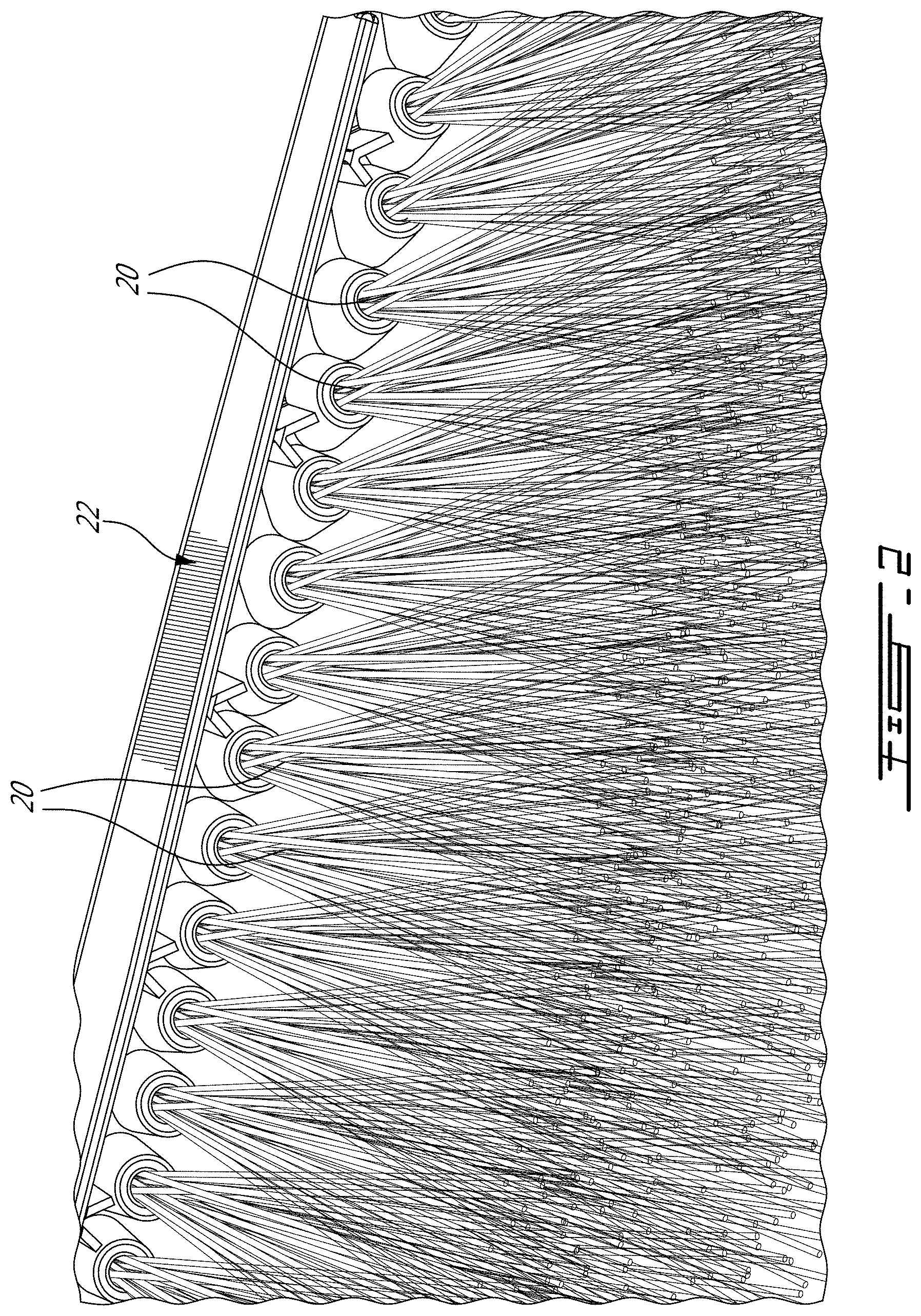
[0009] FIG. 2 is a detail of a broom head according to an embodiment of an aspect of the disclosure;
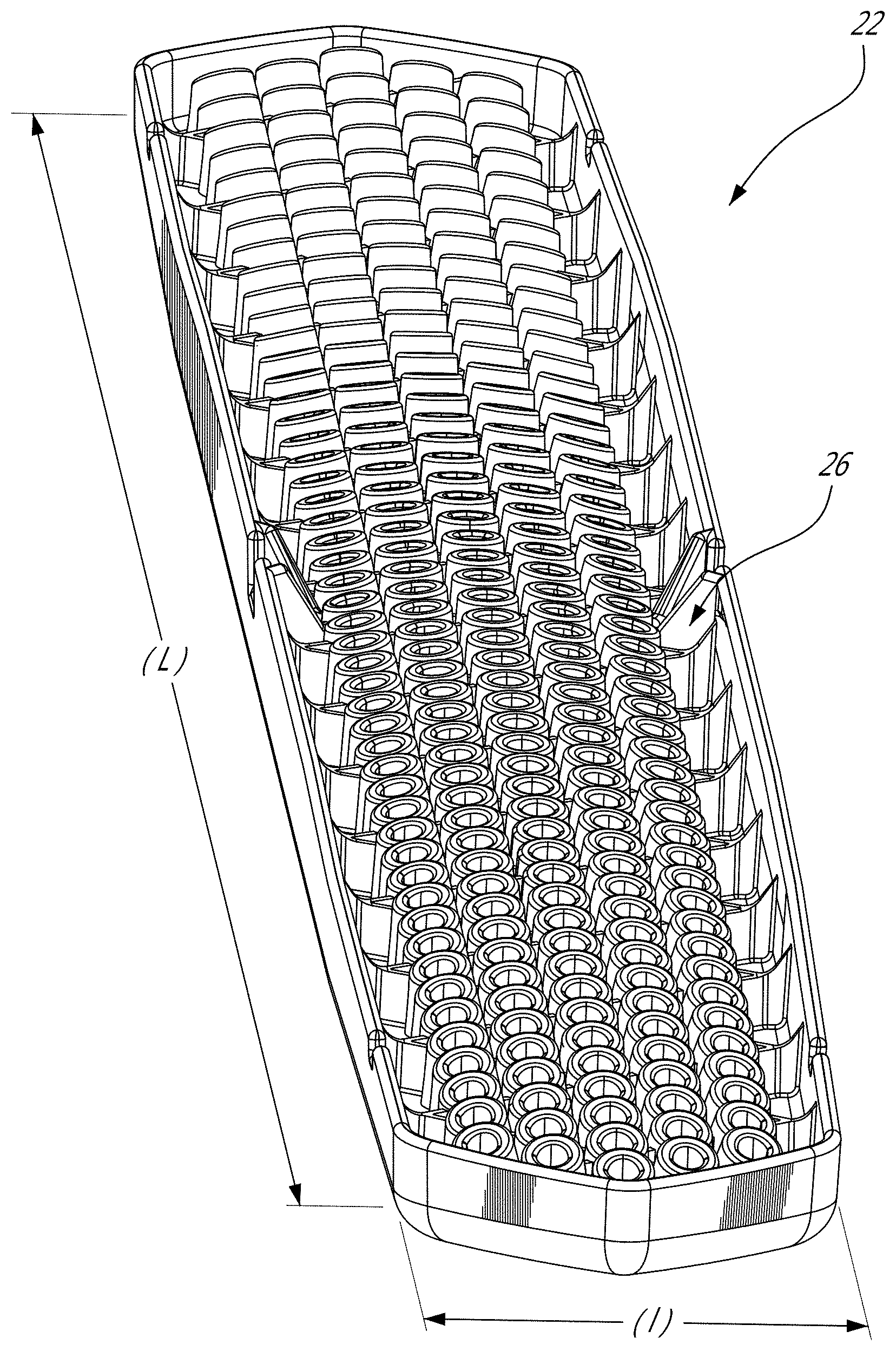
[0010] FIG. 3 is an underside view of a shell for a broom head according to an embodiment of an aspect of the disclosure;
[0011] FIG. 4 is an underside view of a shell for a broom head according to an embodiment of an aspect of the disclosure;
[0012] FIG. 5 is a side view of a shell for a broom head according to an embodiment of an aspect of the disclosure;
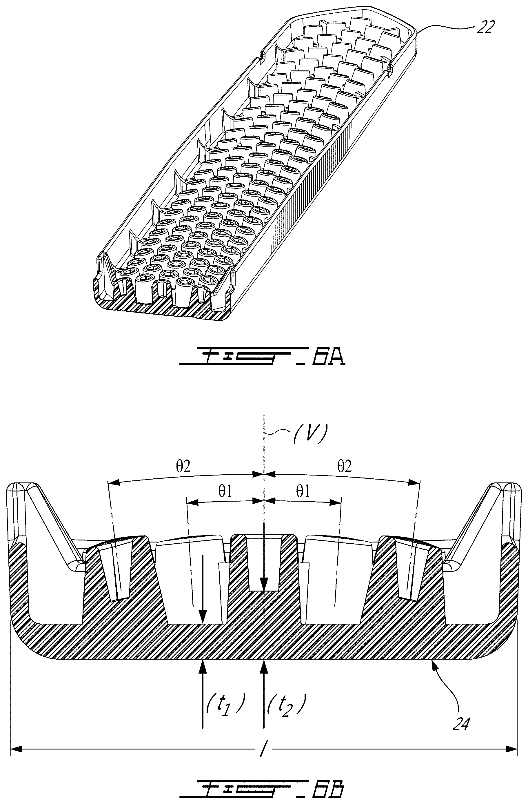
[0013] FIG. 6A is a partial underside view of a shell for a broom head according to an embodiment of an aspect of the disclosure;
[0014] FIG.6B is a cross section of FIG. 1A;
[0015] FIG. 7A is a cross section of pre-sockets of an as-molded shell for a broom head, with a socket shape shown in phantom lines, according to an embodiment of an aspect of the disclosure;
[0016] FIG. 7B is a cross section of sockets of a shell for a broom head according to an embodiment of an aspect of the disclosure;
[0017] FIG. 7C is a cross section of sockets of a shell for a broom head;
[0018] FIG. 8A and FIG. 8B show bristles according to an embodiment of an aspect of the disclosure; and
[0019] FIG. 9 shows sections of broom heads of the art compared to of a broom head according to an embodiment of an aspect of the disclosure.
DESCRIPTION OF EMBODIMENTS OF THE INVENTION
[0020] The present invention is illustrated by the following non-limiting examples.
[0021] FIG. 1 shows a broom 10 comprising a broom head 12 connected at a distal end of a handle 14, by a bracket 16 for example.
[0022] The broom head 12 comprises a working surface, generally indicated as 18 in FIG. 1, opposite the handle 14, providing a contact and brushing surface with a surface to be swept. The brushing surface 18 comprises bristles 20, supported on the underneath of the broom head 12 by a shell 22.
[0023] FIGS. 3 to 7 show the shell 22 according to an embodiment of an aspect of the disclosure.
[0024] The shell 22 is molded as a single piece of a length (L) and a width (I) (FIG. 4). The shell 22 comprises a top surface 24 and a bottom surface 26. The shell 22 may be molded in PP, PEHD, ABS for example.
[0025] The top surface 24 is generally flat; a slight convexity is shown in FIG. 1 or 5 for example. A bracket 16 as shown in FIG.1 may be used for connection between the handle 14 and the top surface 24 of the broom head 12.
[0026] As best seen in FIGS. 3, 4 and 6 for instance, the bottom surface 26 comprises a pattern of molded housings 42, referred to herein as pre-sockets. The pre-sockets 42 are selectively localised, and inclined relative to the normal (V) to the plan of the shell 22; the longitudinal axis of each pre-socket 42 has a selected angle relative to this axis (V) perpendicular to the bottom surface 26, depending on its position along the length (L) and across the width (I) of the broom head (see for example angles .theta.1, .theta.2 in FIG. 6B).
[0027] The depth of each presocket relative to the height (t) of the shell 22 is selected in relation to its respective inclination angle relative to the normal (V) to the plan of the shell 22 so that the shell 22 may be demolded, i.e. without undue bending effect for example. The inclination angle of the presockets relative to the normal (V) to the plan of the shell 22 is typically comprised in a range between about 0 and about 30.degree.. When thus molded and removed from the mold, the shell 22 is a thin, essentially hollow, one-piece molded part having a top surface and a bottom surface separated by of a maximum height (t), and comprising a pattern of presockets on the bottom surface, thereby comprising a minimised amount of molded material.
[0028] The as-molded shell 22 is then positioned in a tufting machine, the bottom surface 26 thereof facing the tufting head. In a first pass of the tufting head, the pre-sockets 42 (FIG. 7A) are drilled into sockets 50 (FIG. 7B; and FIG.7A in phantom line) of an inclination angle depending on the position along the length and across the width of the broom head. Sockets 50 as shown in FIG. 7B have a depth allowing constrainingly securing tufts 20 of bristles 20 (see for instance FIG. 8b as opposed to FIG. 8A for example), each at a precise position and angle, in following passes of the tufting head. Such depths of the sockets, depending on their angle, could not be molded in the first place. Once the tufts 33 are clamped to the bottom of the sockets 50, in the thickness (t2) of material of the shell underneath the socket as shown in FIG. 6B for example, the top surface 24 of the broom head is free of any marks due to the clamping of the bristles.
[0029] The bristles 20 may be made of natural fibers, such as such as Palmyra for example, or synthetic or polymeric fibers, such as Nylon for example. The number and/or density and/or diameter and/or length of the bristles 20 and the inclination angles of the bristles 20 across the bottom surface 26 of the tool head are selected depending on a target firmness or stiffness of the brushing surface of the broom head.
[0030] Fibers 30 may be folded into tufts 33 as shown in FIGS. 8A, 8B for instance, then a tuft 33 as shown in FIG. 8B is inserted within a socket 50 and clamped to a bottom of the socket 50 (in the thickness (t2) of material of the shell underneath the socket as shown in FIG. 6B for example) using a clamp 32 for instance.
[0031] As best seen in FIGS. 6, each socket 50 has an angle selected depending on its location along the length and across the width of the broom head (see for example FIG. 6B). The thickness of the wall of the broom head is minimised, with a larger thickness underneath the sockets 50 allowing clamping of the tufts at the bottom of the sockets 50 (see FIG. 6B t.sub.2 larger than t.sub.1).
[0032] FIG. 7A shows a pre-socket 42, which may be finished into a socket 50 according to an embodiment of an aspect of the present disclosure as shown in FIG. 7B. As people in the art will appreciate, sockets of a depth and inclination angle as shown in FIGS. 7B or 7C cannot be molded as demolding issues arise from the inclination angle and undercuts resulting from the selected geometry, which is not an issue in case of sockets with a longitudinal axis aligned with the normal (V) to the plan of the shell 22.
[0033] Bristles may be more inclined relative to the direction (V) perpendicular to the plane of the broom head as they are positioned closer to the edges of the broom head (see for example FIG. 6B).
[0034] A range of tufts pattern configuration may be selected, by selecting the rigidity, the inclinations angles, the length, the diameter, the cross section, the coloring, and /or the density of the bristles and/or tufts for example. Patterns may include rows aligned with an edge of the shell.
[0035] The broom head may be connected to the handle as discussed hereinabove, thereby forming a broom (see FIG. 1 for instance); it may alternatively be used as a hand brush.
[0036] A minimum amount of molded material is used to form the present tool head by molding the shell including presockets.
[0037] In contrast to broom heads of the art typically being massive blocks of material, the present tool head surface is a molded one-piece shell provided with sockets (FIG. 9, right hand side). Molding cycles are shortened due to thin walls of the shell, as cooling time is minimized. The present tool head has a reduced weight, typically from 600 g in the art down to 300 g for example.
[0038] The scope of the claims should not be limited by the embodiments set forth in the examples, but should be given the broadest interpretation consistent with the description as a whole.
* * * * *
D00000
D00001
D00002
D00003
D00004
D00005
D00006
D00007
D00008
D00009
XML
uspto.report is an independent third-party trademark research tool that is not affiliated, endorsed, or sponsored by the United States Patent and Trademark Office (USPTO) or any other governmental organization. The information provided by uspto.report is based on publicly available data at the time of writing and is intended for informational purposes only.
While we strive to provide accurate and up-to-date information, we do not guarantee the accuracy, completeness, reliability, or suitability of the information displayed on this site. The use of this site is at your own risk. Any reliance you place on such information is therefore strictly at your own risk.
All official trademark data, including owner information, should be verified by visiting the official USPTO website at www.uspto.gov. This site is not intended to replace professional legal advice and should not be used as a substitute for consulting with a legal professional who is knowledgeable about trademark law.