Cable With Integral Sensing Elements For Fault Detection
Yates; Douglas A. ; et al.
U.S. patent application number 16/475750 was filed with the patent office on 2019-10-31 for cable with integral sensing elements for fault detection. This patent application is currently assigned to GoLock Technology, Inc.. The applicant listed for this patent is GoLock Technology, Inc.. Invention is credited to Edward J. Gross, Steven R. Jones, Frank Murtland, Douglas A. Yates.
| Application Number | 20190334578 16/475750 |
| Document ID | / |
| Family ID | 62791120 |
| Filed Date | 2019-10-31 |

| United States Patent Application | 20190334578 |
| Kind Code | A1 |
| Yates; Douglas A. ; et al. | October 31, 2019 |
CABLE WITH INTEGRAL SENSING ELEMENTS FOR FAULT DETECTION
Abstract
Disclosed herein are cable systems that include a cable defining a sensing path and comprising a working strand and one or more sensing strands, a signal source to impart a test signal between a first terminal and a second terminal, a sensor to detect the test signal, a transmitter to transmit the test signal to a receiver, and an indicator to generate a display indicative of the test signal. Certain preferred embodiments describe sensing strands that are arranged in alternating concentric layers and/or extend lengthwise in loops. Such configurations facilitate the detection of breakage, insults, excess tension, or excess bending in the cable. The sensing strands may include a fixed resistor to establish a known resistance and facilitate the detection of small resistive changes.
| Inventors: | Yates; Douglas A.; (Spicewood, TX) ; Jones; Steven R.; (Spicewood, TX) ; Murtland; Frank; (Fort Worth, TX) ; Gross; Edward J.; (Austin, TX) | ||||||||||
| Applicant: |
|
||||||||||
|---|---|---|---|---|---|---|---|---|---|---|---|
| Assignee: | GoLock Technology, Inc. Spicewood TX |
||||||||||
| Family ID: | 62791120 | ||||||||||
| Appl. No.: | 16/475750 | ||||||||||
| Filed: | January 4, 2018 | ||||||||||
| PCT Filed: | January 4, 2018 | ||||||||||
| PCT NO: | PCT/US18/12369 | ||||||||||
| 371 Date: | July 3, 2019 |
Related U.S. Patent Documents
| Application Number | Filing Date | Patent Number | ||
|---|---|---|---|---|
| 62442309 | Jan 4, 2017 | |||
| Current U.S. Class: | 1/1 |
| Current CPC Class: | G01R 31/58 20200101; H01B 7/04 20130101; H01B 7/328 20130101; H01B 7/32 20130101; H04B 3/46 20130101; H04B 10/40 20130101 |
| International Class: | H04B 3/46 20060101 H04B003/46; H01B 7/32 20060101 H01B007/32; G01R 31/02 20060101 G01R031/02; H04B 10/40 20060101 H04B010/40; H01B 7/04 20060101 H01B007/04 |
Claims
1. A cable system comprising: a cable comprising one or more working strands connected to one or more sensing strands to define a sensing path; a first terminal operably connected to said sensing path and comprising a first signal source supported by a power source and configured to impart a test signal into said sensing path; a second terminal operably connected to said sending path and comprising a second sensor and a second transceiver, wherein said second sensor is configured to detect said test signal and said second transceiver is configured to transmit said test signal; and a receiver in communication with said second transceiver and comprising an indicator.
2. The cable system of claim 1, wherein said first terminal further comprises a first sensor and a first transceiver.
3. The cable system of claim 1, wherein said second terminal further comprises a second signal source.
4. The cable system of claim 2, wherein said receiver is in wireless communication with at least one of said first and second transceivers.
5. The cable system of claim 1, wherein said indicator is selected from the group consisting of a lamp, a loudspeaker, and a vibrator.
6. The cable system of claim 1, wherein said first terminal comprises a first pin sized and shaped to be selectively received with a corresponding first receptacle in said receiver, and wherein said second terminal comprises a second pin sized and shaped to be selectively received with a corresponding second receptacle in said receiver, such that said receiver is in wired communication with at least one of said first and second transceivers.
7. The cable system of claim 1, further comprising a fixed resistor positioned in series with said one or more sensing strands, said resistor configured to establish a known resistance along said sensing path, wherein said second sensor is configured to detect an actual resistance along said sensing path in response to said test signal, and is further configured to send a fault message to said receiver when said actual resistance is different from said known resistance.
8. The cable system of claim 1, further comprising an auxiliary terminal operably connected to said sensing path, positioned near said first terminal, and configured to substantially duplicate the functions and operation of said second terminal.
Description
CROSS-REFERENCE TO RELATED APPLICATIONS
[0001] The present application claims the benefit of and priority to U.S. Provisional Application No. 62/442,309, filed Jan. 4, 2017, entitled "Cable with Integral Sensing Elements for Fault Detection" which is incorporated herein by reference in its entirety.
[0002] Certain disclosed embodiments relate to the field of cables and, more specifically, to multi-strand cable systems.
BACKGROUND
[0003] Several types of existing cables include one or more strands having a lesser tensile strength than the cable overall. The lesser-strength strands are typically designed to fail in response to an excessive force; before such a force causes failure of the cable. These strands are sometimes configured to carry an electrical signal. Upon failure, the broken strands will stop conducting the signal and may provide a pre-failure signal to the user. These strands, however, typically provide no indication of the main cable condition in non-failure situations.
[0004] Other cable systems include strain gauges, magnetometers, or other sensors for detecting changes in the condition of the cable. These monitoring systems are typically complex and expensive, involving a number of additional components, many of which are external to the main cable itself.
[0005] Thus, there is a need in the art for improved cables and cable systems.
SUMMARY
[0006] The disclosure features cable systems that include a cable, a first terminal, a second terminal, and a receiver with an indicator. The cable may include one or more working strands connected to one or more sensing strands to define a sensing path. The first terminal may be operably connected to the sensing path and may include a first signal source supported by a power source and configured to impart a test signal into the sensing path. The second terminal may be operably connected to the sending path and may include a second sensor and a second transceiver, wherein the second sensor is configured to detect the test signal and the second transceiver is configured to transmit the test signal. The receiver may be in communication with the second transceiver and may include an indicator.
[0007] The first terminal may further include a first sensor and a first transceiver.
[0008] The second terminal may further include a second signal source.
[0009] The receiver may be in wireless communication with at least one of the first and second transceivers.
[0010] The indicator may be selected from the group consisting of a lamp, a loudspeaker, and a vibrator. In this aspect, the indicator may produce an indication that is visual, audible, or tactile.
[0011] In an exemplary arrangement, the first terminal may include a first pin that is sized and shaped to be selectively received with a corresponding first receptacle in the receiver and the second terminal may include a second pin sized and shaped to be selectively received with a corresponding second receptacle in the receiver, such that the receiver is in wired communication with at least one of the first and second transceivers.
[0012] The cable system may include a fixed resistor positioned in series with the one or more sensing strands, the resistor configured to establish a known resistance along the sensing path. The second sensor may be configured to detect an actual resistance along the sensing path in response to the test signal, and may be further configured to send a fault message to the receiver when the actual resistance is different from the known resistance.
[0013] The cable system may further include an auxiliary terminal that is operably connected to the sensing path, positioned near the first terminal, and configured to substantially duplicate the functions and operation of the second terminal.
BRIEF DESCRIPTION OF THE DRAWING
[0014] Features of the various embodiments disclosed will become more apparent in the following detailed description, in which reference is made to the appended drawing figures, which are incorporated in and constitute a part of this specification. For the purpose of illustration, the drawing figures show embodiments that are presently preferred; however, the invention is not limited to the precise arrangements and instrumentalities shown. In the drawing:
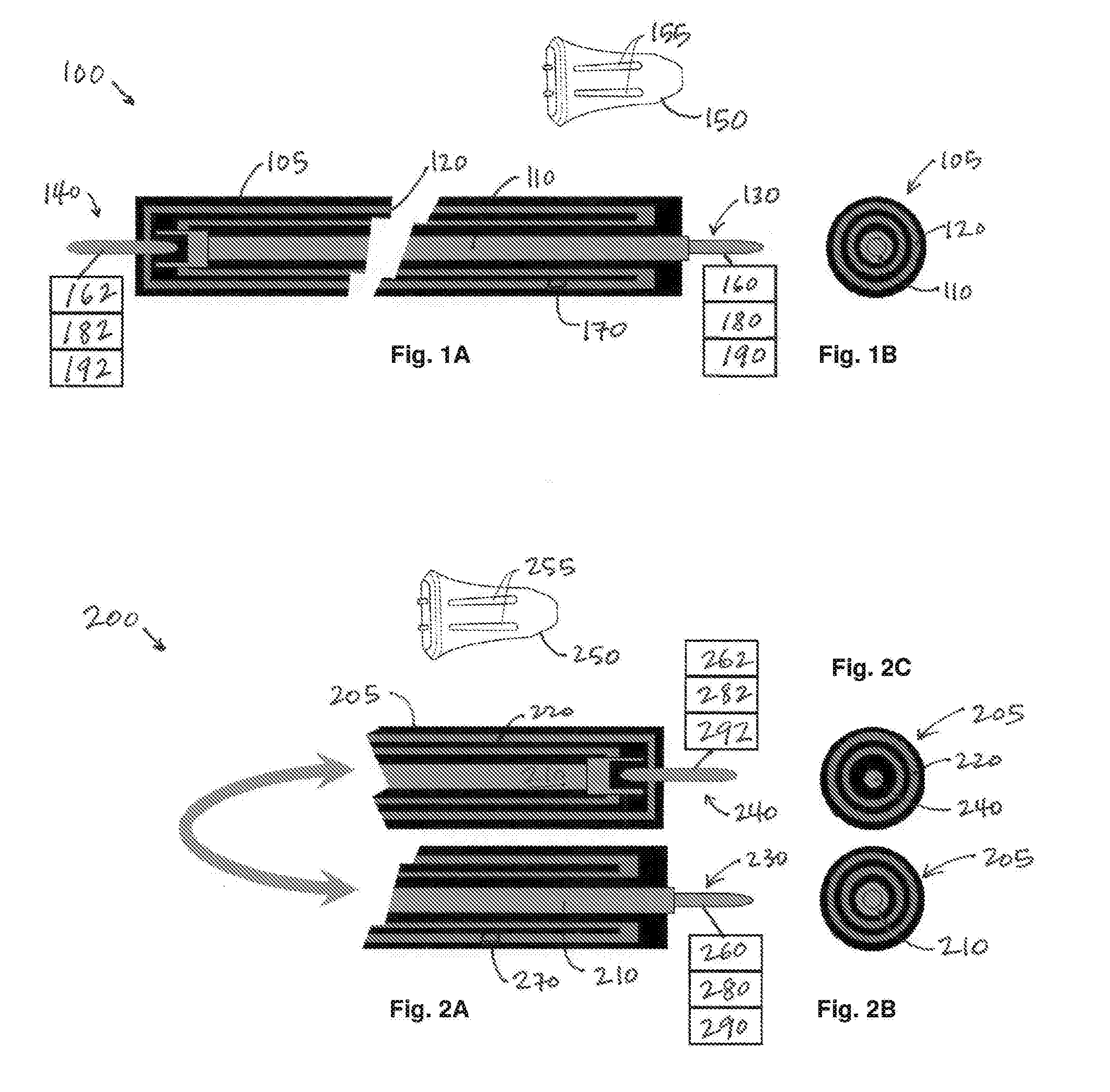
[0015] FIG. 1A is a schematic, side view of a cable system in accordance with a first preferred embodiment.
[0016] FIG. 1B is a schematic, end view of a cable system in accordance with the first preferred embodiment.
[0017] FIG. 2A is a schematic, side view of a cable system in accordance with a second preferred embodiment.
[0018] FIG. 2B is a schematic, end view of a first end of a cable system in accordance with the second preferred embodiment.
[0019] FIG. 2C is a schematic, end view of a second end of a cable system in accordance with the second preferred embodiment.
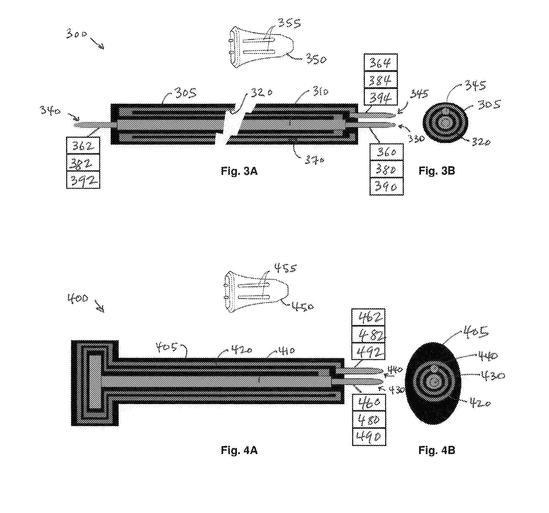
[0020] FIG. 3A is a schematic, side view of a cable system in accordance with a third preferred embodiment.
[0021] FIG. 3B is a schematic, end view of a cable system in accordance with the third preferred embodiment.
[0022] FIG. 4A is a schematic, side view of a cable system in accordance with a fourth preferred embodiment.
[0023] FIG. 4B is a schematic, end view of a cable system in accordance with the fourth preferred embodiment.
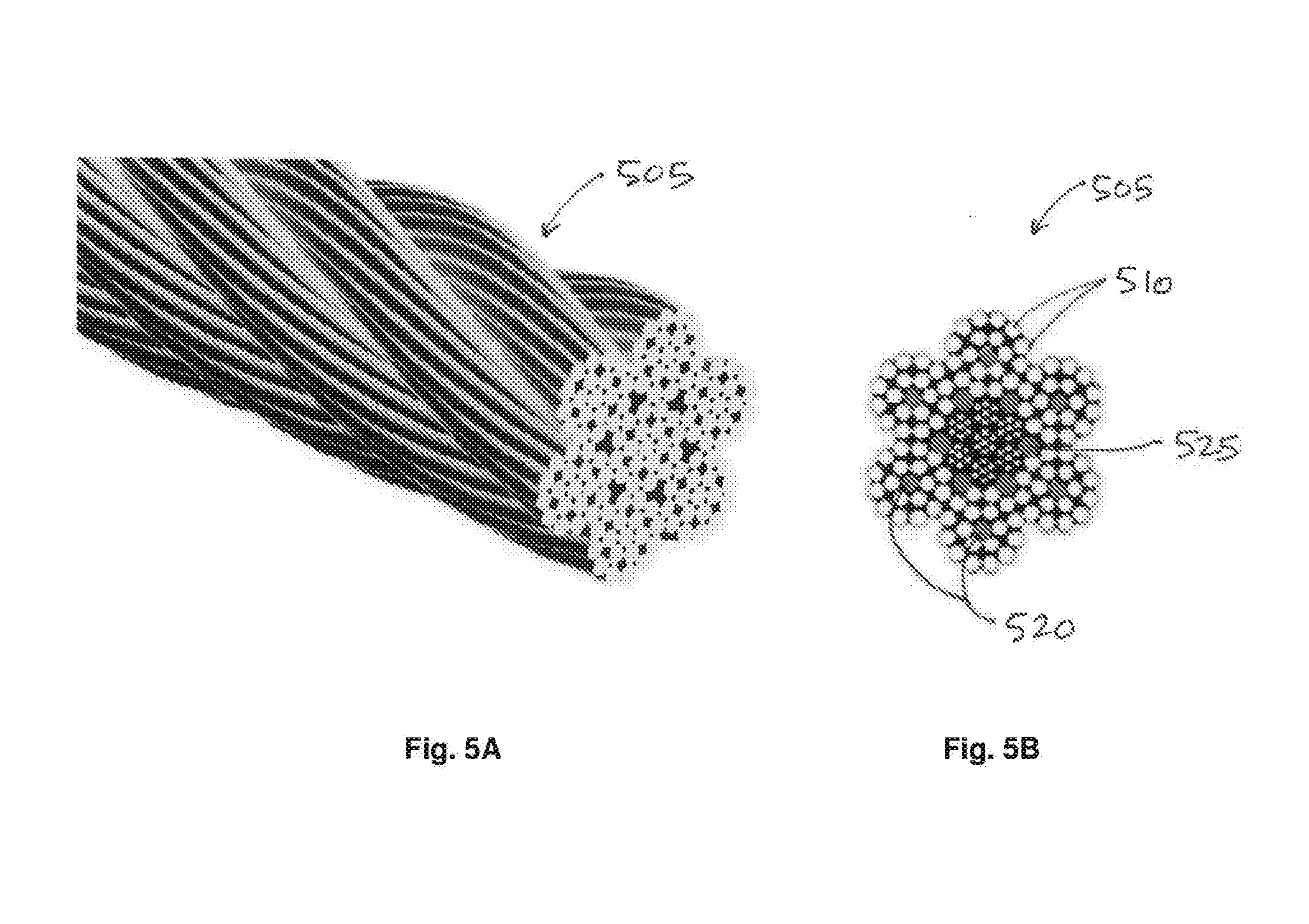
[0024] FIG. 5A is a schematic, side view of a cable system in accordance with a fifth preferred embodiment.
[0025] FIG. 5B is a schematic, end view of a cable system in accordance with the fifth preferred embodiment.
[0026] Corresponding reference numbers indicate corresponding parts or elements throughout the several views of the drawing.
DETAILED DESCRIPTION OF VARIOUS EMBODIMENTS
[0027] The present systems and apparatuses and methods are understood more readily by reference to the following detailed description, examples, drawings, and claims, and their previous and following description. However, before the present devices, systems, and/or methods are disclosed and described, it is to be understood that this invention is not limited to the specific devices, systems, and/or methods disclosed unless otherwise specified, as such can, of course, vary. It is also to be understood that the terminology used herein is for the purpose of describing particular aspects only and is not intended to be limiting.
[0028] Like parts are marked throughout the following description and drawings with the same reference numerals. The drawings may not be to-scale and certain features may be shown exaggerated in scale or in somewhat schematic format in the interest of clarity, conciseness, and to convey information.
[0029] The following description of the invention is provided as an enabling teaching of the invention in its best, currently known embodiment. To this end, those skilled in the relevant art will recognize and appreciate that many changes can be made to the various aspects of the invention described herein, while still obtaining the beneficial results of the present invention. It will also be apparent that some of the desired benefits of the present invention can be obtained by selecting some of the features of the present invention without utilizing other features. Accordingly, those who work in the art will recognize that many modifications and adaptations to the present invention are possible and can even be desirable in certain circumstances and are a part of the present invention. Thus, the following description is provided as illustrative of the principles of the present invention and not in limitation thereof.
[0030] As used throughout, the singular forms "a," "an" and "the" include plural referents unless the context clearly dictates otherwise. Thus, for example, reference to a component can include two or more such components unless the context indicates otherwise.
[0031] Ranges can be expressed herein as from "about" one particular value, and/or to "about" another particular value. When such a range is expressed, another aspect includes from the one particular value and/or to the other particular value. Similarly, when values are expressed as approximations, by use of the antecedent "about," it will be understood that the particular value forms another aspect. It will be further understood that the endpoints of each of the ranges are significant both in relation to the other endpoint, and independently of the other endpoint.
[0032] As used herein, the terms "optional" or "optionally" mean that the subsequently described event or circumstance may or may not occur, and that the description includes instances where said event or circumstance occurs and instances where it does not.
[0033] Although many of the systems and methods described herein are discussed in the context of a cable for use with a portable locking device for securing personal property, the technology disclosed herein is also useful and applicable in a variety of other contexts. For example, the cable systems described herein would be useful and applicable for all types of systems where there is a need or desire to monitor the condition of one or more cables, including cables used in transportation (elevators, automobiles, aircraft, spacecraft, watercraft, agricultural equipment, train locomotives, cable cars, and the like), in manufacturing and industrial processes (drilling, mining, conveyors, robots, hoists and lifts, and the like), and in heavy-duty applications (lifting, hoisting, towing, winching, mooring, and the like). Cable systems with sensing elements may be particularly useful for cables that are subjected to repetitive motion and/or extreme environmental conditions (water, toxic chemicals, UV radiation, nuclear process radiation, and other harsh elements). Remote monitoring of cable systems may be particularly useful for cables that are placed in remote locations where routine or periodic inspection is difficult, expensive, or impossible.
[0034] The term "cable" as used herein refers to generally elongate rope or wire. The cable may be made of natural material, synthetic material, or a combination in any suitable proportion of natural and synthetic materials. The cable may include material that is laid, wound, braided, plaited, or otherwise interlaced according to structures known in the art.
[0035] The term "strands" as used herein refers to generally elongate cable elements such as a threads, yarns, filaments, fibers, cords, and wires, but also refers to and includes cable elements that are formed into or shaped like bands, strips, or ribbons.
First Embodiment
[0036] Referring to FIG. 1A and FIG. 1B, a cable system 100 according to a first preferred embodiment is illustrated. The cable 105, as shown, may include one or more working strands 110 and one or more sensing strands 120. Together, the strands 110, 120 define a sensing path. The strands 110, 120 may be comprised of one or more conductive wires. Accordingly, the strands 110, 120 are capable of transmitting an electrical signal between a first terminal 130 and a second terminal 140. The terminals 130, 140 are operably connected to the cable 105 and preferably, but not necessarily, connected to opposing ends of the cable 105. The terminals 130, 140 may be connected at locations between the opposing ends of the cable 105.
[0037] The working strands 110 are described as active or working because they are engaged in performing one or more functions of the cable system 100, such as providing structural support, conveying a mechanical force (for lifting or towing, for example), or carrying an electric current or signal.
[0038] The working strands 110 and/or the sensing strands 120 may be fully conductive (such as copper wire, ferrous wire, metal foil, wound wire, or other conductive flexible material) or partially conductive (such as resistive wire, carbon filament, carbon-impregnated rubber, synthetic, or other partially-conductive material)--or some combination of both types. The sensing strands 120 may be insulated and/or electrically isolated from other strands in the cable 105.
[0039] The sensing strands 120 form a sensing circuit that may be characterized as having a known resistance (R-set) or a known range of resistance (R-min to R-max). The sensing strands 120 in the sensing circuit may also have one or more other known characteristics, such as a known capacitance, a known signal attenuation, or a known impedance (Z-set) or known range of impedances (Z-min to Z-max) (where impedance is the effective resistance of a circuit to an AC signal). These characteristics may be established as a known quantity or as a range of quantities (min to max). Although the cable systems are described herein in terms of resistance, the present invention includes both DC (direct current) schemes and AC (alternating current) schemes for sensing, detecting, and measuring the characteristics of a circuit.
[0040] Any change in the resistance or other characteristic of the sensing strands 120 present in the cable system 100 may indicate a breakage (complete or partial loss of continuity), an insult (by rubbing or compression, for example), an excess tension (stretching), an excess bending (indicating excess wear-and-tear caused by usage and/or tampering or other insult).
[0041] As shown in FIG. 1A, the one or more sensing strands 120 may be looped back and forth along the length of the cable 105. Looping back and forth may be used in order to establish or raise the total known resistance (R-set) to a desired level, making it easier to detect changes in resistance. The sensing strands 120 may also include a fixed resistor 170 or other resistive element, positioned in series with one or more sensing strands 120. In many cable systems, the resistance for a single strand or wire is very low, making it more difficult to detect minor changes in resistance. Adding a fixed resistor 170 raises the known resistance, making it easier to detect changes in resistance. The fixed resistor 170 may be embedded in one or more of the sensing strands 120 or otherwise positioned in series (or in parallel) in order to establish a desired total resistance.
[0042] The sensing strands 120 may be arranged in a number of alternating, generally concentric layers, as shown in FIG. 1B. The sensing strands 120 may extend lengthwise along all or part of the cable 105, looping back and forth within or along the outer coating layer that surrounds the one or more working strands 110. Any number of layers of sensing strands 120 may be placed in the coating layer, depending on the desired number of layers, loops, and/or endpoint connections. In the configuration shown in FIG. 1A and FIG. 1B, any interruption of the integrity of the cable 105 by cutting (or any significant compression or pinching of the cable 105) would `short` the conductive sensing strands 120 together, across any intermediate insulating layers, thereby changing the impedance of the detection path and generating a fault condition. In this aspect, the cable system 100 generates a fault condition that would provide a pre-failure fault message and a warning to users before a catastrophic failure of the working strand 110, indicating that the cable 105 has been significantly compressed, pinched, or otherwise compromised during use. In this aspect, the cable system 100 offers a pre-failure warning for a safety-critical cables 105 or wires, such as those used on elevators, automobiles, aircraft, spacecraft, automobiles, train locomotives, cable cars, and the like.
[0043] The first terminal 130 may include a first signal source 160, a first sensor 180, and a first transceiver 190. Likewise, the second terminal 140 may include a second signal source 162, a second sensor 182, and a second transceiver 192. According to one exemplary configuration involves a test signal that is generated by the first signal source 160; accordingly, the second signal source 162 may not be present at the second terminal 140. The test signal may be received by the second sensor 182; accordingly, in this configuration, the first sensor 162 may or may not be present. The second sensor 182 may generate one or more fault messages and relay them to the second transceiver 192 for transmission to a remote receiver 150; accordingly, in this configuration, the first transceiver 190 may or may not be present in the first preferred embodiment of the cable system 100.
[0044] In accordance with one exemplary configuration, the first signal source 160 may include a local power source for imparting a test signal such as a known test voltage (V-test) into one or more of the strands 110, 120 and along the sensing path. The test signal may include an electrical signal, such as the test voltage (V-test), or it may include a radio frequency (RF) signal or a light signal (transmitted along fiber optic cable, for example). The power may be provided by an external source, such as a battery, or it may be an active element within the cable system 100 itself (for example, an internal element providing a power source such that the cable 105 itself amplifies or modifies the input voltage (V-test) as part of its function or its characteristic signature). The test signal may be imparted at the first terminal 130 and then sensed at the second terminal 140. In this aspect, the cable system 100 senses and measures the actual resistance (R-actual) of the one or more strands 110, 120 in the cable 105. Any difference between the known resistance (R-set) and the actual resistance (R-actual).
[0045] The first signal source 160 may include a signal generator (analog or digital), a function generator, a waveform generator, of any other suitable signal generator known in the art. The first signal source 160 may also include a processor. Under normal operating conditions, the test signal imparted by the first signal source 160 may freely traverse the strands 110, 120 along the sensing path between the terminals 130, 140 and may be sensed or detected by the second sensor 182. When one or more of the strands 110, 120 is insulted or compromised, the test signal may be diminished or eliminated--a condition that is sensed or detected by the second sensor 182. For example, the second sensor 182 may be configured to detect or measure the actual resistance (R-actual) along the sensing path. If the actual resistance (R-actual) is sufficiently different from the known resistance (R-set), then the second sensor 182 and may be further configured to send a fault message to the second transceiver 192 which, in turn, transmits the fault message to a receiver 150. The receiver 150, as shown, may be a device located remote from the cable 105 that is configured to receive and/or send messages wirelessly. The receiver 150 may include one or more indicators 155. Upon receiving the fault message, the receiver 150 may be configured to cause the indicators 155 to illuminate, change color, sound an audible signal, produce a tactile signal such as vibrating, or otherwise generate a sign or indication that a fault message has been detected and received. The receiver 150 may also be configured to send a warning or maintenance message to one or more predetermined users by any of a variety of wireless and wired messaging techniques.
[0046] The first signal source 160 may include a local circuit or microchip that is configured to check the condition of the cable 105 by sending the known voltage (V-test) at periodic intervals, to detect whether a fault condition exists and (if so) to illuminate the one or more indicators 155 on the receiver 150. Alternatively, the local circuit or microchip may be configured to sense an interrupt to the circuit, wherein the interrupt indicates a change in resistance that is equal to or greater than a predetermined threshold value. Upon detection of such an interrupt, the local circuit or microchip may be configured to then initiate and send the known voltage (V-test) in order to test the circuit and detect and/or measure the change in condition.
[0047] For a cable system that operates using a DC detection scheme, the known voltage (V-test) may be a constant, zero-frequency voltage signal applied to a DC circuit. The resistance R may be the variable to be measured when detecting changes in a DC circuit.
[0048] For a cable system that operates using an AC detection scheme, the known voltage (V-test) may be a sinusoidal voltage signal applied to an AC circuit. The impedance Z may be the variable to be measured when detecting changes in an AC circuit. The cable system may include an electrical shield in the outer layers of the cable (like a co-ax cable) in order to prevent or minimize radiated noise. The local circuitry may also be configured to measure the actual resistance (or other electrical characteristic) along the sensing path at a first time (R-actual-T1), such as when the cable system 100 is initially placed in use. Thereafter, the first signal source 160 may be configured to re-measure the actual resistance (or other characteristic) at one or more later times (R-actual-Tn). Any difference between the measured resistances or other characteristics would generate a fault message. The first cable system 100 may also include a local memory, such as an EEPROM or serial EEPROM (SEEPROM), for recording measurements and other data about the condition of the cable system 100.
[0049] CONNECTED RECEIVER. The receiver 150, in another exemplary configuration, may be physically connected to one or both of the first and second terminals 130, 140. For example, the terminals 130, 140 may include pins that are sized and shaped to be inserted into receptacles in the receiver 150. In this configuration, the terminals 130, 140 need not include the wireless transceivers 190, 192. Moreover, in this configuration, the receiver 150 may be configured to provide a signal source (instead of or in addition to the signal sources 160, 162 in the terminals 130, 140 respectively). The receiver 150 may also be configured to sense the test signal along the sensing path (instead of or in addition to the sensors 180, 182 in the terminals 130, 140 respectively).
[0050] For this exemplary configuration in which the receiver 150 is physically connected and performs some of all of the functions of the local terminals, the receiver 150 may include a local circuit or microchip that is configured to check the condition of the cable 105 by sending the known voltage (V-test) at periodic intervals, to detect whether a fault condition exists and (if so) to illuminate the one or more indicators 155 on the receiver 150. Alternatively, the local circuit or microchip may be configured to sense an interrupt to the circuit, wherein the interrupt indicates a change in resistance that is equal to or greater than a predetermined threshold value. Upon detection of such an interrupt, the local circuit or microchip may be configured to then initiate and send the known voltage (V-test) in order to test the circuit and detect and/or measure the change in condition.
[0051] For a cable system that operates using a DC detection scheme, the known voltage (V-test) may be a constant, zero-frequency voltage signal applied to a DC circuit. The resistance R may be the variable to be measured when detecting changes in a DC circuit.
[0052] For a cable system that operates using an AC detection scheme, the known voltage (V-test) may be a sinusoidal voltage signal applied to an AC circuit. The impedance Z may be the variable to be measured when detecting changes in an AC circuit. The cable system may include an electrical shield in the outer layers of the cable (like a co-ax cable) in order to prevent or minimize radiated noise. The local circuitry may also be configured to measure the actual resistance (or other electrical characteristic) along the sensing path at a first time (R-actual-T1), such as when the cable system 100 is initially placed in use. Thereafter, the receiver 150 may be configured to re-measure the actual resistance (or other characteristic) at one or more later times (R-actual-Tn). Any difference between the measured resistances or other characteristics would generate a fault message. The receiver 150 may also include a local memory, such as an EEPROM or serial EEPROM (SEEPROM), for recording measurements and other data about the condition of the cable system 100.
Second Embodiment
[0053] Referring to FIG. 2A and FIG. 2B, a cable system 200 according to a second preferred embodiment is illustrated. The second preferred cable system 200 is similar in every way to the first cable system 100 except that the first terminal 230 is located or positioned nearby the second terminal 240, as shown in FIG. 2A. In this orientation, the cable system 200 is arranged in a U-shape like the shackle of a typical padlock.
[0054] According to one exemplary configuration, the first and second terminals 230, 240 of the second cable system 200 may be physically connected to the receiver 250. For example, the terminals 230, 240 may include pins that are sized and shaped to be inserted into receptacles in the receiver 250. In this configuration, the second preferred cable system 200 may appear and operate like the U-shaped shackle of a padlock, wherein the pin of each terminal 230, 240 is selectively inserted into the corresponding receptacles in the receiver 250.
[0055] In this configuration, the terminals 230, 240 need not include the wireless transceivers 290, 292. Moreover, in this configuration, the receiver 250 may be configured to provide a signal source (instead of or in addition to the signal sources 260, 262 in the terminals 230, 240 respectively). The receiver 250 may also be configured to sense the test signal along the sensing path (instead of or in addition to the sensors 280, 282 in the terminals 230, 240 respectively).
Third Embodiment
[0056] Referring to FIG. 3A and FIG. 3B, a combination cable system 300 according to a third preferred embodiment is illustrated. The cable 305, as shown, may include one or more working strands 310 and one or more sensing strands 320. Together, the strands 310, 320 define a sensing path. The strands 310, 320 may be comprised of one or more conductive wires, capable of transmitting an electrical signal.
[0057] The one or more sensing strands 320 may be arranged in a number of alternating, generally concentric layers, as shown in FIG. 3B, extending back and forth along the length of the cable 305. Continuity may be tested along the sensing path by making a connection between the first terminal 330 and the second terminal 340. Continuity may also be tested by making a connection between the first terminal 330 and the auxiliary terminal 345 (which is made easier by locating these two terminals 330, 345 near one another, at a single end of the cable 305. The terminals 330, 340, 345 are operably connected to the cable 305.
[0058] Interrupts in continuity may indicate a short or a break. Changes in resistance or other characteristic may indicate a partial fault or other change along the path, caused by the presence of an additional or different locking device or accessory, for example. In this aspect, the cable system may be used to detect which type of cable is installed or attached between the pins.
[0059] The working strands 310 are described as active or working because they are engaged in performing one or more functions of the cable system 300, such as providing structural support, conveying a mechanical force (for lifting or towing, for example), or carrying an electric current or signal.
[0060] The working strands 310 and/or the sensing strands 320 may be fully conductive (such as copper wire, ferrous wire, metal foil, wound wire, or other conductive flexible material) or partially conductive (such as resistive wire, carbon filament, carbon-impregnated rubber, synthetic, or other partially-conductive material)--or some combination of both types. The sensing strands 320 may be insulated and/or electrically isolated from other strands in the cable 305.
[0061] The sensing strands 320 form a sensing circuit that may be characterized as having a known resistance (R-set) or a known range of resistance (R-min to R-max). The sensing strands 320 in the sensing circuit may also have one or more other known characteristics, such as a known capacitance, a known signal attenuation, or a known impedance (Z-set) or known range of impedances (Z-min to Z-max) (where impedance is the effective resistance of a circuit to an AC signal). These characteristics may be established as a known quantity or as a range of quantities (min to max). Although the cable systems are described herein in terms of resistance, the present invention includes both DC (direct current) schemes and AC (alternating current) schemes for sensing, detecting, and measuring the characteristics of a circuit.
[0062] Any change in the resistance or other characteristic of the sensing strands 320 present in the cable system 300 may indicate a breakage (complete or partial loss of continuity), an insult (by rubbing or compression, for example), an excess tension (stretching), an excess bending (indicating excess wear-and-tear caused by usage and/or tampering or other insult).
[0063] As shown in FIG. 3A, the one or more sensing strands 320 may be looped back and forth along the length of the cable 305. Looping back and forth may be used in order to establish or raise the total known resistance (R-set) to a desired level, making it easier to detect changes in resistance. The sensing strands 320 may also include a fixed resistor 370 or other resistive element, positioned in series with one or more sensing strands 320. In many cable systems, the resistance for a single strand or wire is very low, making it more difficult to detect minor changes in resistance. Adding a fixed resistor 370 raises the known resistance, making it easier to detect changes in resistance. The fixed resistor 370 may be embedded in one or more of the sensing strands 120 or otherwise positioned in series (or in parallel) in order to establish a desired total resistance.
[0064] The sensing strands 320 may be arranged in a number of alternating, generally concentric layers, as shown in FIG. 3B. The auxiliary terminal 345 is also shown in FIG. 3B.
[0065] The third preferred cable system 300 is similar in operation to the first cable system 100. Each of the terminals 330, 340, 345 may include a signal source, a sensor, and a transceiver. The first terminal 330 may include a first signal source 360, a first sensor 380, and a first transceiver 390. The second terminal 340 may include a second signal source 362, a second sensor 382, and a second transceiver 392. The auxiliary terminal 345 may include an auxiliary signal source 364, an auxiliary sensor 384, and an auxiliary second transceiver 394.
[0066] In accordance with one exemplary configuration, the first signal source 360 may include a local power source for imparting a test signal such as a known test voltage (V-test) into one or more of the strands 310, 320 and along the sensing path. The power may be provided by an external source, such as a battery, or it may be an active element within the cable system 300 itself (for example, an internal element providing a power source such that the cable 305 itself amplifies or modifies the input voltage (V-test) as part of its function or its characteristic signature). The test signal may be imparted at the first terminal 330 and then sensed at the second terminal 340 and/or at the auxiliary terminal 345. In this aspect, the cable system 300 senses and measures the actual resistance (R-actual) of the one or more strands 310, 320 in the cable 305. Any difference between the known resistance (R-set) and the actual resistance (R-actual).
[0067] The first signal source 360 may include a signal generator (analog or digital), a function generator, a waveform generator, of any other suitable signal generator known in the art. The first signal source 360 may also include a processor. Under normal operating conditions, the test signal imparted by the first signal source 360 may freely traverse the strands 310, 320 along the sensing path between the terminals 330, 340, 345 and may be sensed or detected by the second sensor 382 (and/or the auxiliary sensor 384). When one or more of the strands 310, 320 is insulted or compromised, the test signal may be diminished or eliminated--a condition that is sensed or detected by the second sensor 382. For example, the second sensor 382 may be configured to detect or measure the actual resistance (R-actual) along the sensing path. If the actual resistance (R-actual) is sufficiently different from the known resistance (R-set), then the second sensor 382 and may be further configured to send a fault message to the second transceiver 392 which, in turn, transmits the fault message to a receiver 350. The receiver 350, as shown, may be a device located remote from the cable 305 that is configured to receive and/or send messages wirelessly. The receiver 350 may include one or more indicators 155. Upon receiving the fault message, the receiver 350 may be configured to cause the indicators 155 to illuminate, change color, sound an audible signal, produce a tactile signal such as vibrating, or otherwise generate a sign or indication that a fault message has been detected and received.
[0068] The first signal source 360 may include a local circuit or microchip that is configured to check the condition of the cable 305 by sending the known voltage (V-test) at periodic intervals, to detect whether a fault condition exists and (if so) to illuminate the one or more indicators 355 on the receiver 350. Alternatively, the local circuit or microchip may be configured to sense an interrupt to the circuit, wherein the interrupt indicates a change in resistance that is equal to or greater than a predetermined threshold value. Upon detection of such an interrupt, the local circuit or microchip may be configured to then initiate and send the known voltage (V-test) in order to test the circuit and detect and/or measure the change in condition.
[0069] For a cable system that operates using a DC detection scheme, the known voltage (V-test) may be a constant, zero-frequency voltage signal applied to a DC circuit. The resistance R may be the variable to be measured when detecting changes in a DC circuit.
[0070] For a cable system that operates using an AC detection scheme, the known voltage (V-test) may be a sinusoidal voltage signal applied to an AC circuit. The impedance Z may be the variable to be measured when detecting changes in an AC circuit. The cable system may include an electrical shield in the outer layers of the cable (like a co-ax cable) in order to prevent or minimize radiated noise. The local circuitry may also be configured to measure the actual resistance (or other electrical characteristic) along the sensing path at a first time (R-actual-T1), such as when the cable system 300 is initially placed in use. Thereafter, the first signal source 360 may be configured to re-measure the actual resistance (or other characteristic) at one or more later times (R-actual-Tn). Any difference between the measured resistances or other characteristics would generate a fault message. The first cable system 300 may also include a local memory, such as an EEPROM or serial EEPROM (SEEPROM), for recording measurements and other data about the condition of the cable system 300.
[0071] The receiver 350, in another exemplary configuration, may be physically connected to one or both of the first and second terminals 330, 340. For example, the terminals 330, 340 may include pins that are sized and shaped to be inserted into receptacles in the receiver 350. In this configuration, the terminals 330, 340 (and 345) need not include the wireless transceivers 390, 392, 394. Moreover, in this configuration, the receiver 350 may be configured to provide a signal source (instead of or in addition to the signal sources 360, 362, 364). The receiver 350 may also be configured to sense the test signal along the sensing path (instead of or in addition to the sensors 380, 382, 384).
Fourth Embodiment
[0072] Referring to FIG. 4A and FIG. 4B, a single-ended cable system 400 according to a fourth preferred embodiment is illustrated. The cable 405, as shown, may include one or more working strands 410 and one or more sensing strands 420. Together, the strands 410, 420 define a sensing path. The strands 410, 420 may be comprised of one or more conductive wires, capable of transmitting an electrical signal.
[0073] The one or more sensing strands 420 may be arranged in a number of alternating, generally concentric layers, as shown in FIG. 4B, extending back and forth along the length of the cable 405. Continuity may be tested along the sensing path by making a connection between the first terminal 430 and the second terminal 440.
[0074] The fourth preferred cable system 400 is similar in operation to the first cable system 100. Each terminal 430, 440 may include a signal source, a sensor, and a transceiver. The first terminal 430 may include a first signal source 460, a first sensor 480, and a first transceiver 490. The second terminal 440 may include a second signal source 462, a second sensor 482, and a second transceiver 492.
Fifth Embodiment
[0075] Referring to FIG. 5A and FIG. 5B, a spiral-wound, multi-strand cable system according to a fifth preferred embodiment is illustrated. The cable 505, as shown in FIG. 5B, may include one or more working strands 510 and one or more sensing strands 520. Together, the strands 510, 520 define a sensing path. The strands 510, 520 may be comprised of one or more conductive wires, capable of transmitting an electrical signal. The cable 505 may also include filler strands 525 and/or open spaces between the one or more groups of working and sensing strands 510, 520.
[0076] This disclosure also describes methods of detecting fault conditions in cable or cable systems. In general, the methods comprise providing a sensing path, imparting a test signal along the sensing path between a first terminal and a second terminal, sensing the test signal, transmitting the test signal or a fault message to a receiver, and activating an indicator to inform or alert users about the condition of the cable. The methods may be used in accordance with any of the embodiments and configurations described herein.
[0077] Although several embodiments have been described herein, those of ordinary skill in art, with the benefit of the teachings of this disclosure, will understand and comprehend many other embodiments and modifications for this technology. The invention therefore is not limited to the specific embodiments disclosed or discussed herein. Many other embodiments and modifications are intended to be included within the scope of the appended claims. Moreover, although specific terms are occasionally used herein, as well as in the claims that follow, such terms are used in a generic and descriptive sense only, and should not be construed as limiting the claims or the described invention.
* * * * *
D00000
D00001
D00002
D00003
XML
uspto.report is an independent third-party trademark research tool that is not affiliated, endorsed, or sponsored by the United States Patent and Trademark Office (USPTO) or any other governmental organization. The information provided by uspto.report is based on publicly available data at the time of writing and is intended for informational purposes only.
While we strive to provide accurate and up-to-date information, we do not guarantee the accuracy, completeness, reliability, or suitability of the information displayed on this site. The use of this site is at your own risk. Any reliance you place on such information is therefore strictly at your own risk.
All official trademark data, including owner information, should be verified by visiting the official USPTO website at www.uspto.gov. This site is not intended to replace professional legal advice and should not be used as a substitute for consulting with a legal professional who is knowledgeable about trademark law.