Loop Heat Pipe With Different Pipe Diameters
TSENG; Chuan-Chi ; et al.
U.S. patent application number 16/015841 was filed with the patent office on 2019-10-31 for loop heat pipe with different pipe diameters. The applicant listed for this patent is TAI-SOL ELECTRONICS CO., LTD.. Invention is credited to Yueh-Lung CHUANG, Chuan-Chi TSENG, Xiao-Long WU.
| Application Number | 20190331431 16/015841 |
| Document ID | / |
| Family ID | 68291984 |
| Filed Date | 2019-10-31 |


| United States Patent Application | 20190331431 |
| Kind Code | A1 |
| TSENG; Chuan-Chi ; et al. | October 31, 2019 |
LOOP HEAT PIPE WITH DIFFERENT PIPE DIAMETERS
Abstract
A loop heat pipe with different pipe-diameters includes: an evaporation chamber having a casing and a wick disposed therein, the wick not occupying the casing fully such that an evaporation space is formed therebetween; a condensation element externally provided with a heat-dissipating unit and internally having a circulation channel, the circulation channel having a vapor connection-end and a liquid connection-end having a smaller inner diameter than the vapor connection-end; a vapor delivery-pipe having an end connecting to the casing and communicating with the evaporation space and another end connecting to the vapor connection-end of the condensation element and communicating with the circulation channel; and a liquid delivery-pipe having an end connecting to the casing and communicating with the casing and another end connecting to the liquid connection-end of the condensation element and communicating with the circulation channel, the liquid delivery-pipe having a smaller inner diameter than the vapor delivery-pipe.
| Inventors: | TSENG; Chuan-Chi; (TAIPEI CITY, TW) ; CHUANG; Yueh-Lung; (TAIPEI CITY, TW) ; WU; Xiao-Long; (WUJIANG CITY, JIANGSU PROVINCE, CN) | ||||||||||
| Applicant: |
|
||||||||||
|---|---|---|---|---|---|---|---|---|---|---|---|
| Family ID: | 68291984 | ||||||||||
| Appl. No.: | 16/015841 | ||||||||||
| Filed: | June 22, 2018 |
| Current U.S. Class: | 1/1 |
| Current CPC Class: | F28D 15/043 20130101; F28F 13/08 20130101 |
| International Class: | F28D 15/04 20060101 F28D015/04 |
Foreign Application Data
| Date | Code | Application Number |
|---|---|---|
| Apr 26, 2018 | TW | 107114329 |
Claims
1. A loop heat pipe with different pipe diameters, comprising: an evaporation chamber having a casing and a wick disposed in the casing, the wick not occupying the casing fully so as for an evaporation space to be formed between the wick and the casing; a condensation element externally provided with a heat-dissipating unit and internally having a circulation channel, the circulation channel having an end configured to be a vapor connection end and another end configured to be a liquid connection end, wherein the vapor connection end has a greater inner diameter than the liquid connection end; a vapor delivery pipe having an end connecting to the casing and being in communication with the evaporation space and another end connecting to the vapor connection end of the condensation element and being in communication with the circulation channel; and a liquid delivery pipe having an end connecting to the casing and being in communication with the inside of the casing and another end connecting to the liquid connection end of the condensation element and being in communication with the circulation channel, wherein the liquid delivery pipe has a smaller inner pipe diameter than the vapor delivery pipe.
2. The loop heat pipe with different pipe diameters according to claim 1, wherein the casing comprises a lid and a receiving box, with the wick disposed in the receiving box, the lid covering the receiving box, the receiving box being defined by sidewalls each having a first hole and a second hole, wherein the first hole, the second hole and the evaporation space are positioned on a same side of the receiving box, the first hole having a greater diameter than the second hole, the first hole being in communication with the vapor space and penetrated by an end of the vapor delivery pipe so as to connect to the casing, and the second hole being penetrated by an end of the liquid delivery pipe so as to connect to the casing.
3. The loop heat pipe with different pipe diameters according to claim 2, wherein the condensation element is a hollow-cored, U-shaped pipe, with the circulation channel disposed in the U-shaped pipe and penetrating to reach two ends of the U-shaped pipe, the two ends being configured to be the vapor connection end and the liquid connection end, respectively, the vapor connection end having a greater inner diameter than the liquid connection end.
4. The loop heat pipe with different pipe diameters according to claim 1, wherein the casing comprises a lid and a receiving box, with the wick disposed in the receiving box, the lid covering the receiving box, the receiving box being defined by sidewalls each having a first hole and a second hole, wherein the first hole and the evaporation space are positioned on a same side of the receiving box, whereas the first hole and the second hole are positioned on different sides of the receiving box, respectively, the first hole having a greater diameter than the second hole, the first hole being in communication with the vapor space and penetrated by an end of the vapor delivery pipe so as to connect to the casing, and the second hole being penetrated by an end of the liquid delivery pipe so as to connect to the casing.
5. The loop heat pipe with different pipe diameters according to claim 4, wherein the condensation element is a hollow-cored tube, with the circulation channel disposed in the hollow-cored tube and penetrating to reach two ends of the hollow-cored tube, the two ends being configured to be the vapor connection end and the liquid connection end, respectively, the vapor connection end having a greater inner diameter than the liquid connection end.
6. The loop heat pipe with different pipe diameters according to claim 2, wherein the condensation element is a rectangular block having therein a pipeline for forming the circulation channel such that two ends of the pipeline form the vapor connection end and the liquid connection end, respectively, allowing the vapor connection end and the liquid connection end to protrude from the block, the vapor connection end having a greater inner diameter than the liquid connection end.
7. The loop heat pipe with different pipe diameters according to claim 1, wherein the wick is made of sintered copper powder and has a plurality of channels each having a channel opening in communication with the vapor space.
Description
BACKGROUND OF THE INVENTION
1. Technical Field
[0001] The present disclosure relates to heat-dissipating devices and, more particularly, to a loop heat pipe with different pipe diameters.
Related Art
[0002] CN106052448A discloses a loop heat pipe which has a hollow-cored pipe. The hollow-cored pipe bends backward and divides into two pipeline channels, namely an evaporation segment and a condensation segment. The two tube ends and opposing pipe walls are flat wall surfaces. A closed end lid has a closed end and an inserted end. The inserted end has an opening which the two tube ends are inserted into, and thereby the two tube ends fit together. CN106052449A discloses a loop heat pipe which has an evaporation segment and a condensation segment and divides into two hollow-cored pipes. The two tube ends are inserted into a closed end lid. The closed end lid has a closed end and an inserted end. The inserted end is configured to be an opening which the two tube ends are inserted into. Then, the gap between the opening and the two tube ends is filled with a filler. CN106091761A discloses a loop heat pipe which has an evaporation segment and a condensation segment and divides into two pipeline hollow-cored pipes. The two tube ends are inserted into a closed end lid. The closed end lid has a closed end and an inserted end. The inserted end is configured to have two openings which the two tube ends are inserted into, respectively. Each of the aforesaid three citations discloses an evaporation route and a condensation route, and both of which are configured to be pipes of the same diameter and are not specially designed to facilitate ease of flow of liquid. As a result, a liquid working fluid circulating is unlikely to return to the evaporation route smoothly, thereby slowing down its circulation and reducing its efficiency of heat dissipation.
BRIEF SUMMARY OF THE INVENTION
[0003] It is an objective of the present disclosure to provide a loop heat pipe comprising a vapor delivery pipe and a liquid delivery pipe with a smaller diameter than the vapor delivery pipe so as to form fluid slugs such that the liquid working fluid can return to an evaporation chamber smoothly and thereby enhance efficiency of heat dissipation.
[0004] In order to achieve the above and other objectives, the present disclosure provides a loop heat pipe with different pipe diameters, comprising: an evaporation chamber having a casing and a wick disposed in the casing, the wick not occupying the casing fully so as for an evaporation space to be formed between the wick and the casing; a condensation element externally provided with a heat-dissipating unit and internally having a circulation channel, the circulation channel having an end configured to be a vapor connection end and another end configured to be a liquid connection end, wherein the vapor connection end has a greater inner diameter than the liquid connection end; a vapor delivery pipe having an end connecting to the casing and being in communication with the evaporation space and another end connecting to the vapor connection end of the condensation element and being in communication with the circulation channel; and a liquid delivery pipe having an end connecting to the casing and being in communication with the inside of the casing and another end connecting to the liquid connection end of the condensation element and being in communication with the circulation channel, wherein the liquid delivery pipe has a smaller inner pipe diameter than the vapor delivery pipe.
[0005] According to the present disclosure, the liquid delivery pipe has a smaller diameter than the vapor delivery pipe such that a liquid working fluid forms fluid slugs which are then moved under a pressure difference and even in the absence of a capillary force, so as to allow the liquid working fluid to return to an evaporation chamber smoothly and thereby enhance efficiency of heat dissipation.
BRIEF DESCRIPTION OF THE SEVERAL VIEWS OF THE DRAWINGS
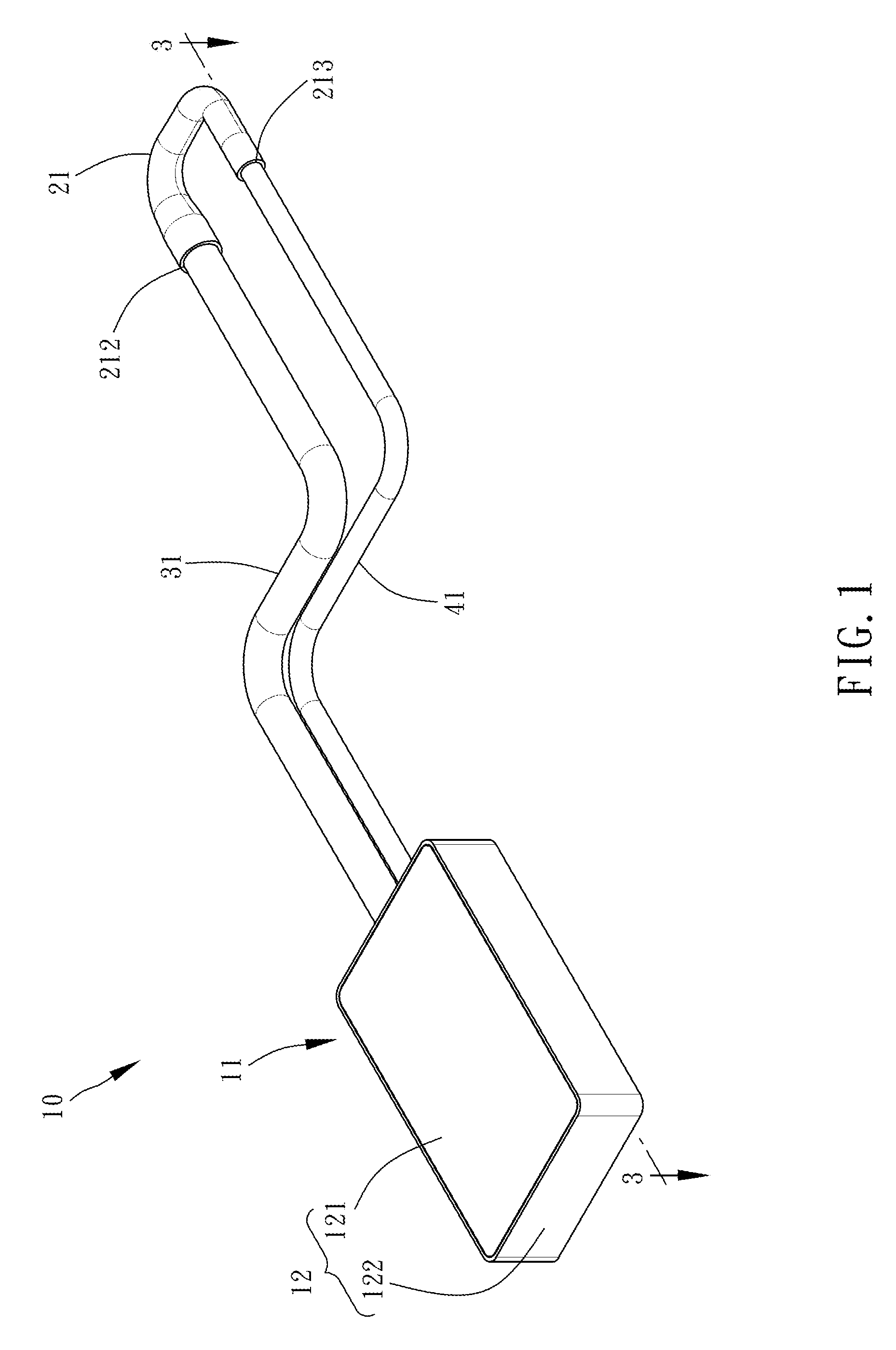
[0006] FIG. 1 is a perspective view of a loop heat pipe with different pipe diameters according to the first preferred embodiment of the present disclosure;
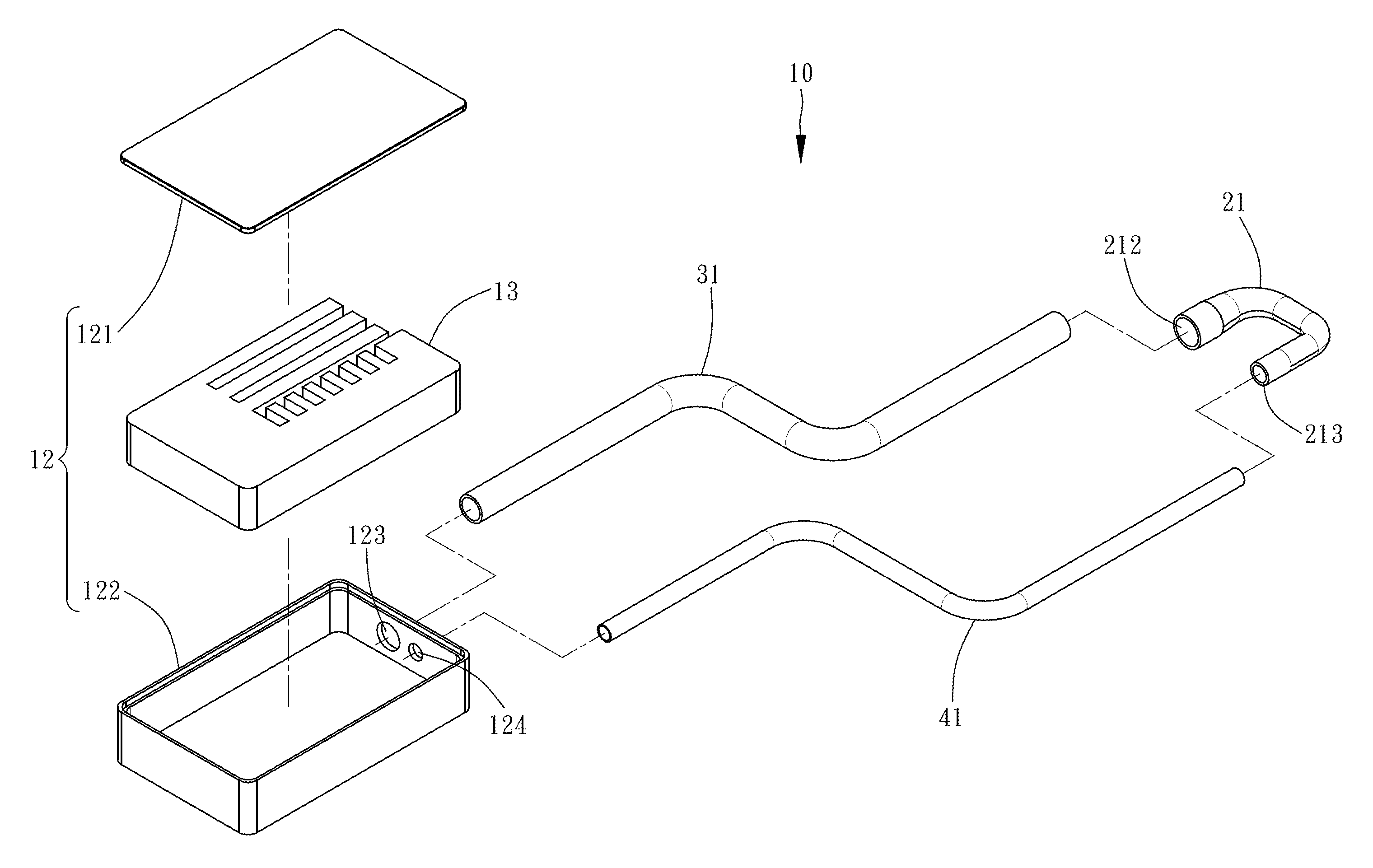
[0007] FIG. 2 is a perspective exploded view of the loop heat pipe with different pipe diameters shown in FIG. 1;
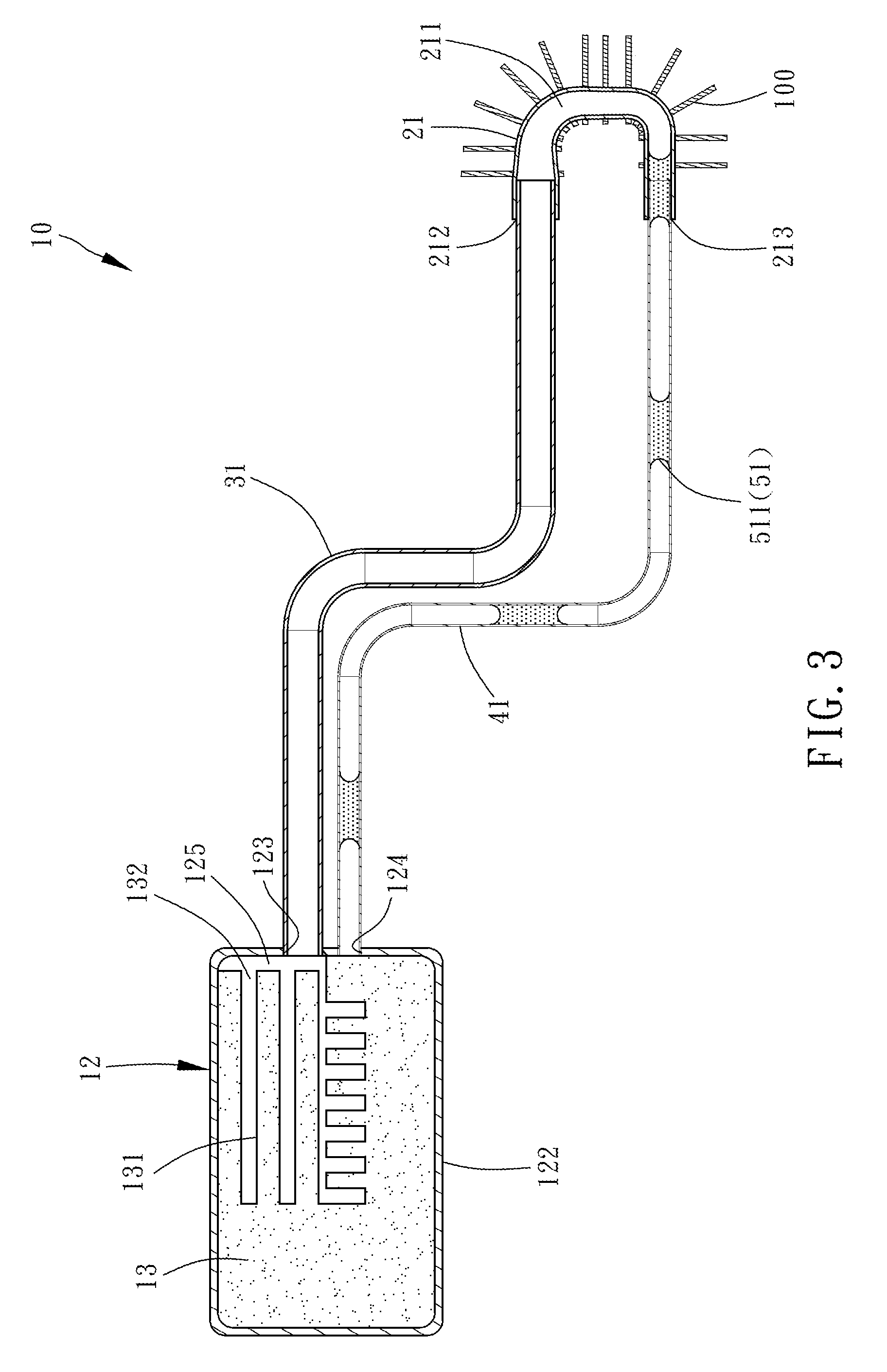
[0008] FIG. 3 is a horizontal cross-sectional view of FIG. 1 plus a cross-sectional view of a heat-dissipating unit;
[0009] FIG. 4 is a perspective view of a loop heat pipe with different pipe diameters according to the second preferred embodiment of the present disclosure;
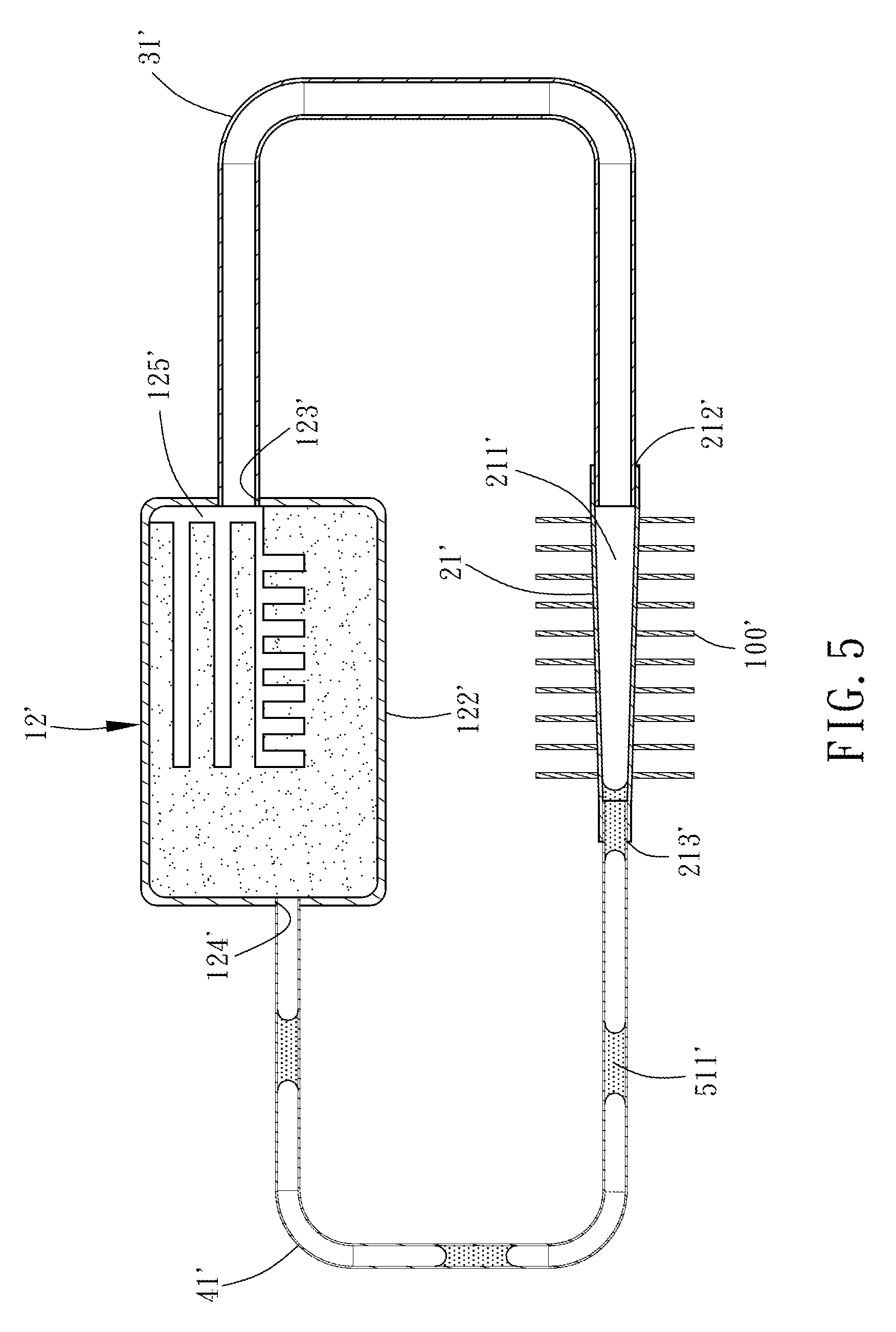
[0010] FIG. 5 is a horizontal cross-sectional view of FIG. 4 plus a cross-sectional view of a heat-dissipating unit;
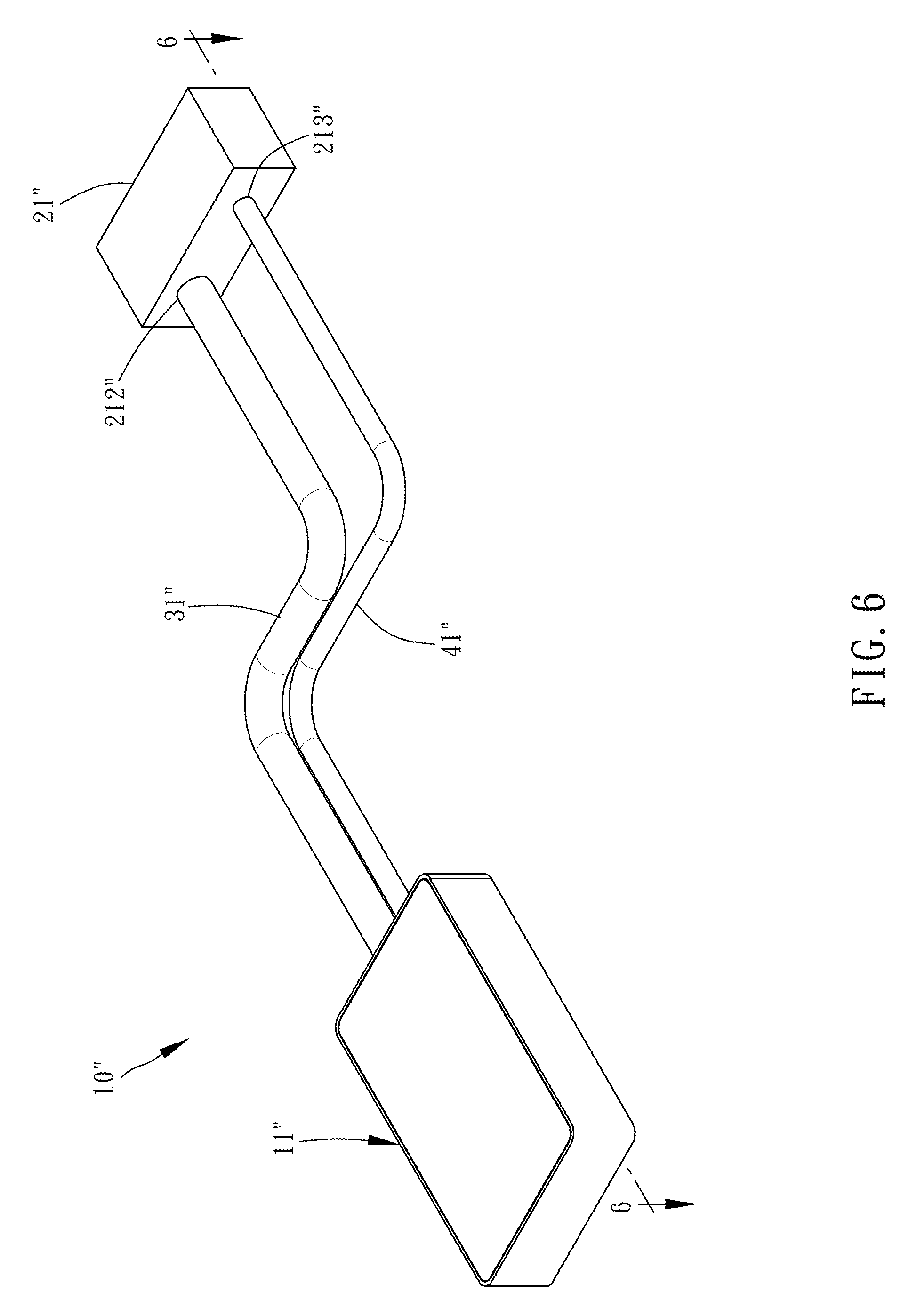
[0011] FIG. 6 is a perspective view of a loop heat pipe with different pipe diameters according to the third preferred embodiment of the present disclosure;
[0012] FIG. 7 is a perspective exploded view of FIG. 6; and
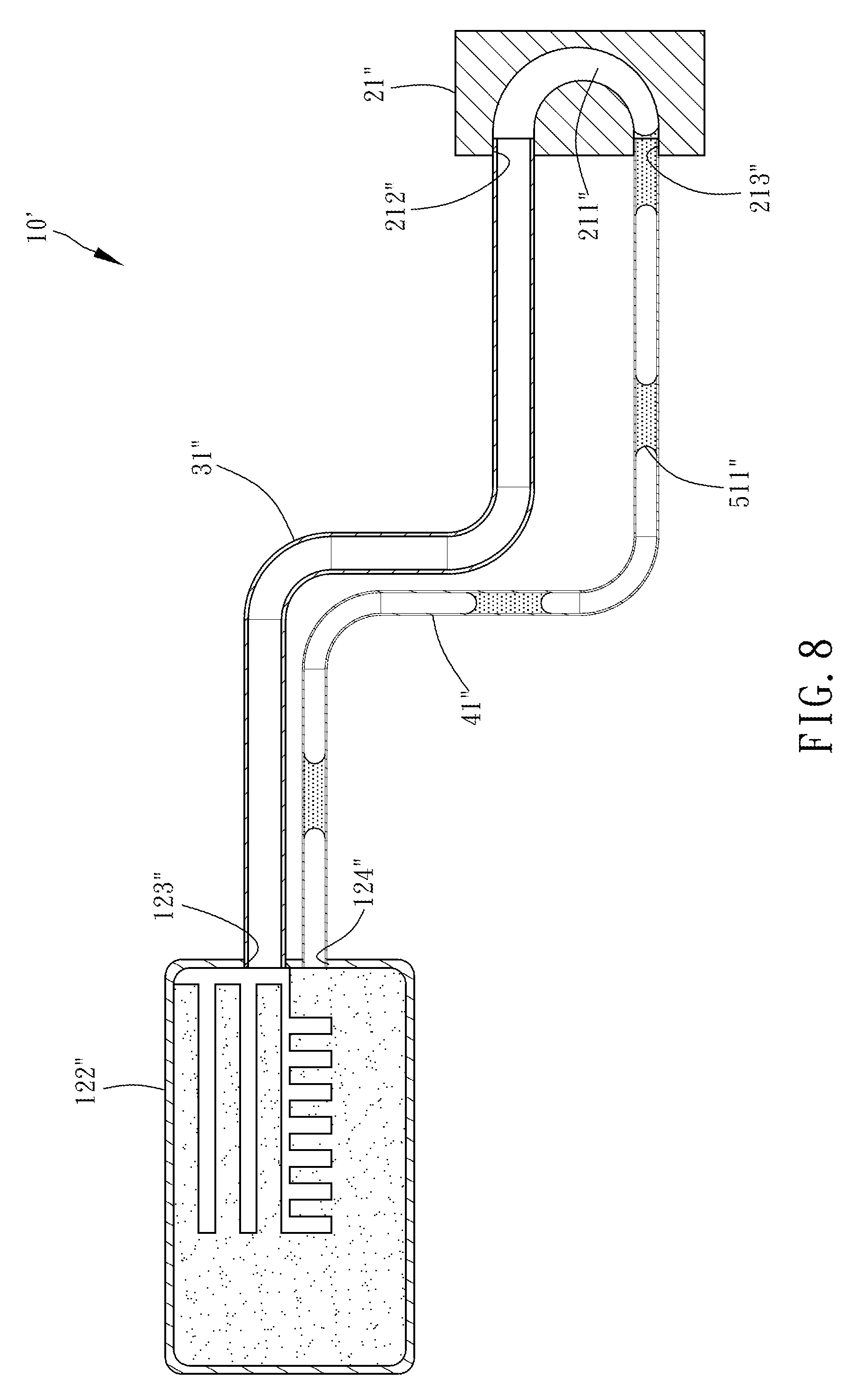
[0013] FIG. 8 is a horizontal cross-sectional view of FIG. 6.
DETAILED DESCRIPTION OF THE INVENTION
[0014] Technical features of the present disclosure are illustrated by preferred embodiments, depicted by drawings, and described below.
[0015] Referring to FIG. 1 through FIG. 3, a loop heat pipe 10 with different pipe diameters according to the first preferred embodiment of the present disclosure essentially comprises an evaporation chamber 11, a condensation element 21, a vapor delivery pipe 31, a liquid delivery pipe 41 and a working fluid 51.
[0016] The evaporation chamber 11 has a casing 12 and a wick 13 disposed in the casing 12. The wick 13 does not occupy the inside of the casing 12 fully and thereby an evaporation space 125 is formed between the wick 13 and the casing 12. The casing 12 comprises a lid 121 and a receiving box 122. The wick 13 is disposed in the receiving box 122. The lid 121 covers the receiving box 122. Each side of the receiving box 122 is defined as a sidewall. Each sidewall has a first hole 123 and a second hole 124. The first hole 123, the second hole 124 and the evaporation space 125 are positioned on the same side of the receiving box 122. The first hole 123 has a larger diameter than the second hole 124. The first hole 123 is in communication with the evaporation space 125 and penetrated by one end of the vapor delivery pipe 31 so as to connect to the casing 12. The second hole 124 is penetrated by one end of the liquid delivery pipe 41 and thus connects to the casing 12. The wick 13 has a plurality of channels 131. The channels 131 each have a channel opening 132 which is in communication with the evaporation space 125. In this embodiment, the wick 13 is made of sintered copper powder.
[0017] In this embodiment, the condensation element 21 is configured to be a hollow-cored, U-shaped pipe externally provided with a heat-dissipating unit 100 and internally having a circulation channel 211 penetrating until it reaches the two ends of the hollow-cored, U-shaped pipe. The circulation channel 211 has one end defined as a vapor connection end 212 and the other end defined as a liquid connection end 213. The inner diameter of the vapor connection end 212 corresponds to the diameter of the first hole 123 of the casing 12 and is greater than the inner diameter of the liquid connection end 213. The inner diameter of the liquid connection end 213 corresponds to the diameter of the second hole 124 of the casing 12. In practice, the heat-dissipating unit 100 is a plurality of fins surrounding the U-shaped pipe.
[0018] The vapor delivery pipe 31 is a hollow-cored tube which curves. The vapor delivery pipe 31 has a predetermined length. The diameter of the vapor delivery pipe 31 corresponds to the inner diameter of the first hole 123 of the casing 12 and the inner diameter of the vapor connection end 212 of the condensation element 21. One end of the vapor delivery pipe 31 penetrates the first hole 123 of the casing 12 and thus is in communication with the evaporation space 125. The other end of the vapor delivery pipe 31 connects to the vapor connection end 212 of the condensation element 21 and is in communication with the circulation channel 211.
[0019] Like the vapor delivery pipe 31, the liquid delivery pipe 41 is a hollow-cored tube which curves. The liquid delivery pipe 41 has a predetermined length. The diameter of the liquid delivery pipe 41 corresponds to the inner diameter of the second hole 124 of the casing 12 and the inner diameter of the liquid connection end 213 of the condensation element 21. The liquid delivery pipe 41 has a smaller inner diameter than the vapor delivery pipe 31. One end of the liquid delivery pipe 41 penetrates the second hole 124 of the casing 12 and thus is in communication with the inside of the casing 12. The other end of the liquid delivery pipe 41 connects to the liquid connection end 213 of the condensation element 21 and is in communication with the circulation channel 211 (as shown in FIG. 3.)
[0020] The working fluid 51 in this embodiment is exemplified by pure water that fills the evaporation chamber 11, is adsorbed to the wick 13, and exists at a portion of the loop heat pipe 10.
[0021] Structural features of the first preferred embodiment are described above. Operation-related features of the first preferred embodiment are described below.
[0022] Given the aforesaid structures, before using the loop heat pipe 10, a user places a heat source, such as an electronic device, on the evaporation chamber 11. After operating for a time period, the heat source (not shown) begins to generate heat. The heat thus generated is transferred, by conduction, from the heat source to the evaporation chamber 11 and then to the wick 13. The working fluid 51 is stored in the wick 13 mostly in liquid form. As soon as heat is taken up by the wick 13, the temperature of the wick 13 rises such that a liquid working fluid stored in the wick 13 takes up sufficient heat and thus gradually evaporates into a gaseous working fluid. The gaseous working fluid moves out of the channel openings 132 of the channels 131 of the wick 13 so as to reach and accumulate in the evaporation space 125; afterward, the gaseous working fluid enters the vapor delivery pipe 31, moves toward the condensation element 21, and finally enters the condensation element 21 through the vapor connection end 212. With the condensation element 21 being externally provided with the heat-dissipating unit 100, the gaseous working fluid passing the condensation element 21 dissipates heat to the surrounding air. As a result, the gaseous working fluid cools and condenses into droplets of the liquid working fluid. Then, the droplets of the liquid working fluid attach to the wall of the condensation element 21. As time passed, the resultant liquid working fluid in droplets becomes massive enough to occupy the liquid connection end 213 quickly and enter the liquid delivery pipe 41 to form fluid slugs 511 defined by the cross sections of the liquid delivery pipe 41, because the diameter of the liquid connection end 213 of the condensation element 21 is so small that the liquid working fluid in droplets can quickly fill it and enter it. Since the liquid delivery pipe 41 has a small diameter, the fluid slugs 511 are moved under a pressure difference in the vapor delivery pipe 31 and the liquid delivery pipe 41 even in the absence of a capillary force such that the fluid slugs 511 move within the liquid delivery pipe 41 easily and quickly. Furthermore, the gaseous working fluid moves continuously from the vapor delivery pipe 31 to the condensation element 21 to produce a force for driving the fluid slugs 511 forward. Finally, the fluid slugs 511 return to the evaporation chamber 11 where the fluid slugs 511 are adsorbed to the wick 13. The aforesaid process recurs and thus guides heat out of the heat source continuously, thereby performing heat dissipation well.
[0023] Therefore, according to the present disclosure, the liquid delivery pipe 41 has a smaller diameter than the vapor delivery pipe 31, and the condensation element 21 which connects to the vapor delivery pipe 31 and the liquid delivery pipe 41 has an advantageous feature: the liquid connection end 213 has a smaller diameter than the vapor connection end 212; hence, the fluid slugs 511 (shown in FIG. 3) can be formed in the liquid delivery pipe 41 despite its small cross-sectional area. Furthermore, since the liquid delivery pipe 41 has a small diameter, the fluid slugs 511 are moved under a pressure difference in the vapor delivery pipe 31 and the liquid delivery pipe 41 even in the absence of a capillary force such that the liquid working fluid can return to the evaporation chamber 11 easily and quickly.
[0024] Referring to FIG. 4 and FIG. 5, a loop heat pipe 10' with different pipe diameters according to the second preferred embodiment of the present disclosure is substantially identical to its counterpart in the first preferred embodiment except for the distinguishing technical features described below.
[0025] The first hole 123' and the evaporation space 125' are positioned on the same side of the receiving box 122'. The first hole 123' and the second hole 124' are positioned on different sides of the receiving box 122', respectively. The first hole 123' has a greater diameter than the second hole 124'. The first hole 123' is in communication with the vapor space 125', is penetrated by one end of the vapor delivery pipe 31', and thus connects to the casing 12'. The second hole 124' is penetrated by one end of the liquid delivery pipe 41' and thus connects to the casing 12'. The condensation element 21' is a hollow-cored tube. The circulation channel 211' is disposed in the hollow-cored tube and penetrates the hollow-cored tube to reach two ends thereof, so as to form the vapor connection end 212' and the liquid connection end 213'. The vapor connection end 212' has a greater inner diameter than the liquid connection end 213'. The heat-dissipating unit 100' has a plurality of fins surrounding the hollow-cored tube.
[0026] The other structures and achievable advantages in the second preferred embodiment are substantially identical to their counterparts in the first preferred embodiment and thus are not described again.
[0027] With the liquid delivery pipe 41' being of a smaller diameter than the vapor delivery pipe 31', the liquid working fluid forms fluid slugs 511' which are then moved under a pressure difference in the vapor delivery pipe 31' and the liquid delivery pipe 41' even in the absence of a capillary force such that the fluid slugs 511' move within the liquid delivery pipe 41' smoothly (as shown in FIG. 5), so as to allow the liquid working fluid to return to the evaporation chamber 11' smoothly and quickly.
[0028] Referring to FIG. 6 through FIG. 8, the loop heat pipe 10'' with different pipe diameters according to the third preferred embodiment of the present disclosure is substantially identical to its counterpart in the first preferred embodiment except for the distinguishing technical features described below.
[0029] The condensation element 21'' in this embodiment is a rectangular block which has therein a pipeline for forming the circulation channel 211''. The two ends of the pipeline are configured to be the vapor connection end 212'' and the liquid connection end 213'', respectively. Both the vapor connection end 212'' and the liquid connection end 213'' protrude from the block. The inner diameters of the vapor connection end 212'' and the liquid connection end 213'' correspond to the diameters of the vapor delivery pipe 31'' and the liquid delivery pipe 41'', respectively. The vapor connection end 212'' has a greater inner diameter than the liquid connection end 213'' and is penetrated by one end of the vapor delivery pipe 31'' so as to be in communication with the circulation channel 211''. The liquid connection end 213'' is penetrated by one end of the liquid delivery pipe 41'' and thus is in communication with the circulation channel 211''. The heat-dissipating unit (not shown) has a plurality of fins directly mounted on the block.
[0030] The other structures and achievable advantages in the third preferred embodiment are substantially identical to their counterparts in the first preferred embodiment and thus are not described again.
[0031] The liquid delivery pipe 41'' has a smaller diameter than the vapor delivery pipe 31''. The condensation element 21'' which connects to the vapor delivery pipe 31'' and the liquid delivery pipe 41'' has an advantageous technical feature: the circulation channel 211'' has a smaller diameter than the liquid connection end 213''. With the vapor connection end 212'' having a larger diameter, not only can the liquid working fluid forms fluid slugs 511'', but the fluid slugs 511'' can also be moved under a pressure difference in the vapor delivery pipe 31'' and the liquid delivery pipe 41'' even in the absence of a capillary force such that the fluid slugs 511'' move within the liquid delivery pipe 41'' smoothly (as shown in FIG. 8), so as to allow the liquid working fluid to return to the evaporation chamber 11'' smoothly and quickly, thereby enhancing the heat dissipation efficiency of the loop heat pipe of the present disclosure.
[0032] In the third preferred embodiment, the first hole 123'' and the second hole 124'' are positioned on the same side of the receiving box 122'', whereas the vapor delivery pipe 31'' and the liquid delivery pipe 41'' are positioned on the same side of the receiving box 122''. The vapor connection end 212'' and the liquid connection end 213'' of the condensation element 21'' operate in conjunction with each other and thus can be penetrated by the vapor delivery pipe 31'' and the liquid delivery pipe 41'', so as to be in communication with the circulation channel 211''. In a variant embodiment (not shown) of the present disclosure, the loop heat pipe with different pipe diameters has technical features as follows: the first hole 123'' and the second hole 124'' are positioned on different sides of the receiving box 122'', respectively; the vapor delivery pipe 31'' and the liquid delivery pipe 41'' are positioned on different sides of the receiving box 122'', respectively; the circulation channel 211'' of the condensation element 21'' penetrates the rectangular block so much that the two ends of the circulation channel 211'' of the condensation element 21'' reaches the two sides of the rectangular block; the vapor connection end 212'' and the liquid connection end 213'' at the two ends of the circulation channel 211'' are penetrated by the vapor delivery pipe 31'' and the liquid delivery pipe 41'', respectively. Therefore, like the second preferred embodiment, the variant embodiment enhances the heat dissipation efficiency of the loop heat pipe of the present disclosure.
* * * * *
D00000
D00001
D00002
D00003
D00004
D00005
D00006
D00007
D00008
XML
uspto.report is an independent third-party trademark research tool that is not affiliated, endorsed, or sponsored by the United States Patent and Trademark Office (USPTO) or any other governmental organization. The information provided by uspto.report is based on publicly available data at the time of writing and is intended for informational purposes only.
While we strive to provide accurate and up-to-date information, we do not guarantee the accuracy, completeness, reliability, or suitability of the information displayed on this site. The use of this site is at your own risk. Any reliance you place on such information is therefore strictly at your own risk.
All official trademark data, including owner information, should be verified by visiting the official USPTO website at www.uspto.gov. This site is not intended to replace professional legal advice and should not be used as a substitute for consulting with a legal professional who is knowledgeable about trademark law.