Loop Heat Pipe Partitioned Into Vapor Channel And Liquid Channel
TSENG; Chuan-Chi ; et al.
U.S. patent application number 16/033497 was filed with the patent office on 2019-10-31 for loop heat pipe partitioned into vapor channel and liquid channel. The applicant listed for this patent is TAI-SOL ELECTRONICS CO., LTD.. Invention is credited to Yueh-Lung CHUANG, Chuan-Chi TSENG, Xiao-Long WU.
| Application Number | 20190331430 16/033497 |
| Document ID | / |
| Family ID | 65431731 |
| Filed Date | 2019-10-31 |


View All Diagrams
| United States Patent Application | 20190331430 |
| Kind Code | A1 |
| TSENG; Chuan-Chi ; et al. | October 31, 2019 |
LOOP HEAT PIPE PARTITIONED INTO VAPOR CHANNEL AND LIQUID CHANNEL
Abstract
A loop heat pipe partitioned into a vapor channel and a liquid channel includes an evaporation chamber, a loop tube, a coupling cover, and a heat-dissipating unit disposed outside the loop tube. The evaporation chamber has a casing. The casing has therein a wick, a working fluid and an evaporation space. The loop tube has a connecting end and an engaging end. The connecting end connects to the casing. The loop tube has therein at least one partition element for partitioning the loop tube into a vapor channel and a liquid channel. The coupling cover is engaged with the engaging end of the loop tube and spaced apart from the at least one partition element by a predetermined distance to thereby form a circulation zone whereby the at least one vapor channel and the liquid channel communicate.
| Inventors: | TSENG; Chuan-Chi; (TAIPEI CITY, TW) ; CHUANG; Yueh-Lung; (TAIPEI CITY, TW) ; WU; Xiao-Long; (WUJIANG CITY, CN) | ||||||||||
| Applicant: |
|
||||||||||
|---|---|---|---|---|---|---|---|---|---|---|---|
| Family ID: | 65431731 | ||||||||||
| Appl. No.: | 16/033497 | ||||||||||
| Filed: | July 12, 2018 |
| Current U.S. Class: | 1/1 |
| Current CPC Class: | F28D 15/0266 20130101; F28D 15/0283 20130101; F28D 15/04 20130101 |
| International Class: | F28D 15/02 20060101 F28D015/02; F28D 15/04 20060101 F28D015/04 |
Foreign Application Data
| Date | Code | Application Number |
|---|---|---|
| Apr 26, 2018 | TW | 107114328 |
Claims
1. A loop heat pipe partitioned into a vapor channel and a liquid channel, comprising: an evaporation chamber having a casing, the casing having therein a wick and being filled with a working fluid, the wick not occupying an inside of the casing fully, so as for an evaporation space to be formed between the wick and the casing; a loop tube having two ends defined as a connecting end and an engaging end, respectively, the connecting end connecting to the casing to allow the loop tube to be in communication with a space within the casing, the loop tube having therein at least one partition element for partitioning the loop tube into at least two channels not in communication with each other, the at least two channels being defined as at least one vapor channel and a liquid channel, respectively; a heat-dissipating unit disposed outside the loop tube and positioned proximate to the engaging end; and a coupling cover engaged with the engaging end of the loop tube and spaced apart from the at least one partition element in the loop tube by a predetermined distance to form a circulation zone, the circulation zone allowing communication between the liquid channel and the at least one vapor channel in the loop tube.
2. The loop heat pipe partitioned into a vapor channel and a liquid channel according to claim 1, wherein the coupling cover has a concave portion, the concave portion being substantially stepwise and hole-shaped and having an opening end of a large diameter, a bottom end of a small diameter, and an annular blocking portion formed between the opening end and the bottom end, such that the engaging end of the loop tube is inserted into the concave portion through the opening end and blocked by the annular blocking portion, and the circulation zone is formed between an end portion of the engaging end of the loop tube and the bottom end of the concave portion of the coupling cover.
3. The loop heat pipe partitioned into a vapor channel and a liquid channel according to claim 1, wherein the at least one partition element is of a smaller length than the loop tube, extends from the connecting end to the engaging end of the loop tube, and forms a retracted space together with an end portion of the engaging end, whereas the coupling cover has a bottom portion of a large diameter, a top portion of a small diameter, and an annular blocking portion formed between the bottom portion and the top portion, such that the top portion of the coupling cover is inserted into and engaged with the retracted space at the engaging end, not only allowing the circulation zone to be formed between the top portion of the coupling cover and the retracted space, but also allowing the engaging end of the loop tube to be blocked by the annular blocking portion and thus positioned in place.
4. The loop heat pipe partitioned into a vapor channel and a liquid channel according to claim 1, wherein the at least one partition element is provided in a plural number, arranged to jointly form a V-shaped pattern when viewed from a sectional perspective, and adapted to partition the loop tube into two vapor channels and one liquid channel.
5. The loop heat pipe partitioned into a vapor channel and a liquid channel according to claim 1, wherein the wick has an extending portion corresponding in position to the liquid channel of the loop tube and protruding into the liquid channel by a specific length.
Description
BACKGROUND OF THE INVENTION
1. Technical Field
[0001] The present disclosure relates to heat-dissipating devices and, more particularly, to a loop heat pipe partitioned into a vapor channel and a liquid channel.
2. Description of Related Art
[0002] CN106052448A discloses a loop heat pipe which has a hollow-cored pipe. The hollow-cored pipe bends backward and divides into two pipeline channels, namely an evaporation segment and a condensation segment. The two pipe ends fit together by a closed end lid. The closed end lid has a closed end and an inserted end. The inserted end has an opening. Opposing pipe walls of the two pipe ends have flat wall surfaces and fit each other tightly; hence, the two pipe ends are inserted into the opening of the closed end lid and thus fit together. CN106052449A discloses a loop heat pipe which has a hollow-cored pipe. The hollow-cored pipe divides to form an evaporation segment and a condensation segment. The loop heat pipe includes a closed end lid which has a closed end and an inserted end. The inserted end has an opening. When the two pipe ends are inserted into the opening, gaps between the opening and the two pipe ends are filled with a gap-filler. The evaporation segments and the condensation segments provided by the aforesaid two citations are pipes of the same diameter and are not specially designed to facilitate ease of flow of liquid formed by condensation. As a result, a liquid working fluid circulating is unlikely to return to an evaporation chamber smoothly, thereby slowing down its circulation and reducing its heat dissipation efficiency. Furthermore, it is difficult for the closed end lid to be engaged with the pipes; in an attempt to overcome this drawback, changing the shape of the pipes or filling the gaps between the opening and the two pipe ends with the gap-filler is a feasible solution but adds to manufacturing costs.
BRIEF SUMMARY OF THE INVENTION
[0003] It is an objective of the present disclosure to partition a loop tube by at least one partition element into at least one vapor channel and one liquid channel, allow the loop tube to be engaged with a coupling cover, form a circulation zone for enabling communication between the at least one vapor channel and the liquid channel in the loop tube, form a fluid slug from a liquid working fluid, move the fluid slug under a pressure difference, allow the liquid working fluid to return to an evaporation chamber smoothly, so as to enhance heat dissipation efficiency.
[0004] In order to achieve the above and other objectives, the present disclosure provides a loop heat pipe partitioned into a vapor channel and a liquid channel, comprising: an evaporation chamber having a casing, the casing having therein a wick and being filled with a working fluid, the wick not occupying an inside of the casing fully, so as for an evaporation space to be formed between the wick and the casing; a loop tube having two ends defined as a connecting end and an engaging end, respectively, the connecting end connecting to the casing to allow the loop tube to be in communication with a space within the casing, the loop tube having therein at least one partition element for partitioning the loop tube into at least two channels not in communication with each other, the at least two channels being defined as at least one vapor channel and a liquid channel, respectively; a heat-dissipating unit disposed outside the loop tube and positioned proximate to the engaging end; and a coupling cover engaged with the engaging end of the loop tube and spaced apart from the at least one partition element in the loop tube by a predetermined distance to form a circulation zone, the circulation zone allowing communication between the liquid channel and the at least one vapor channel in the loop tube.
[0005] Therefore, according to the present disclosure, a loop tube is partitioned by at least one partition element into at least one vapor channel and one liquid channel such that a liquid working fluid forms a fluid slug to be moved under a pressure difference, so as for the liquid working fluid to return to an evaporation chamber smoothly, thereby enhancing heat dissipation efficiency.
BRIEF DESCRIPTION OF THE SEVERAL VIEWS OF THE DRAWINGS
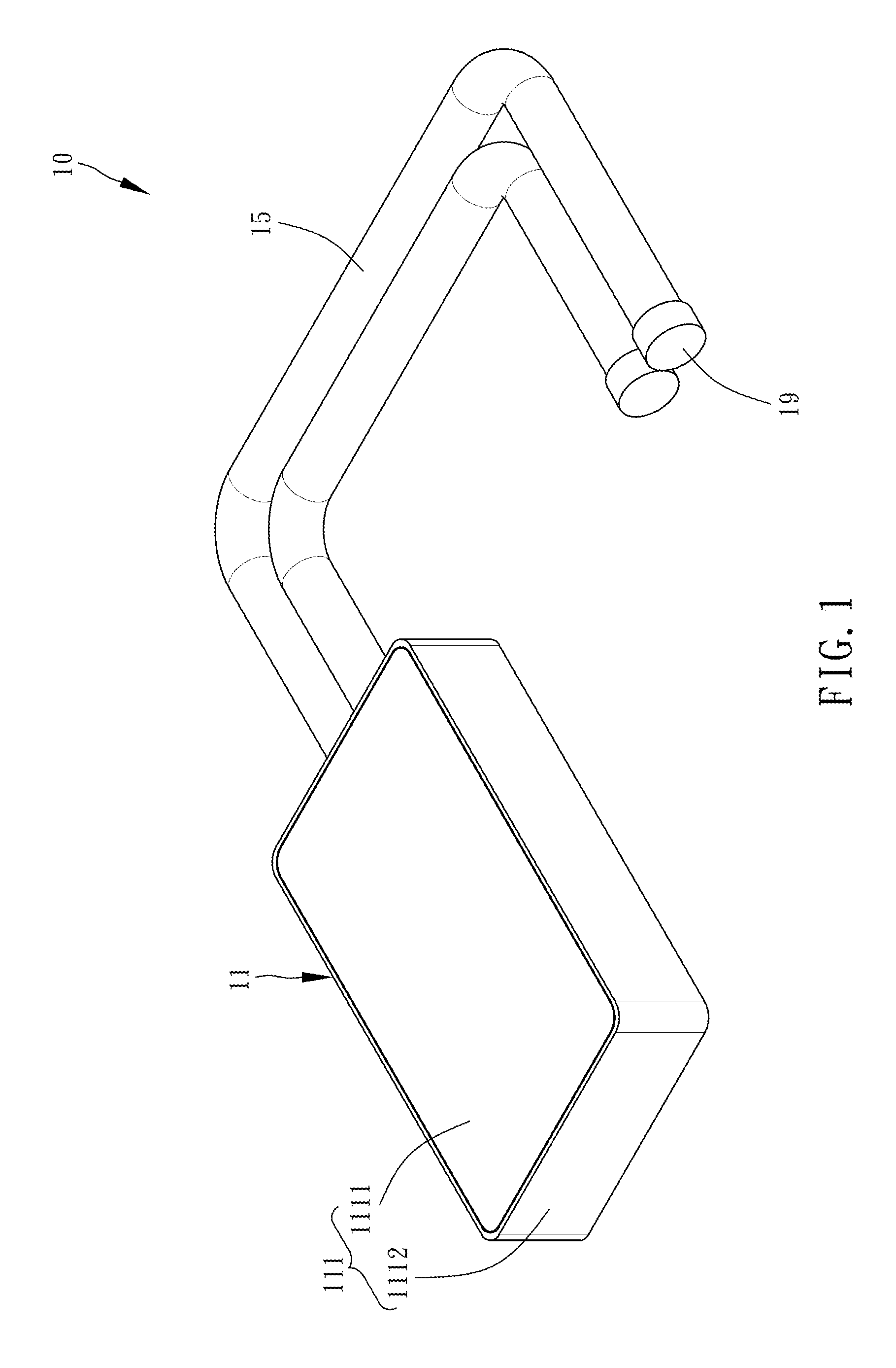
[0006] FIG. 1 is a perspective view of a loop heat pipe according to the first preferred embodiment of the present disclosure;
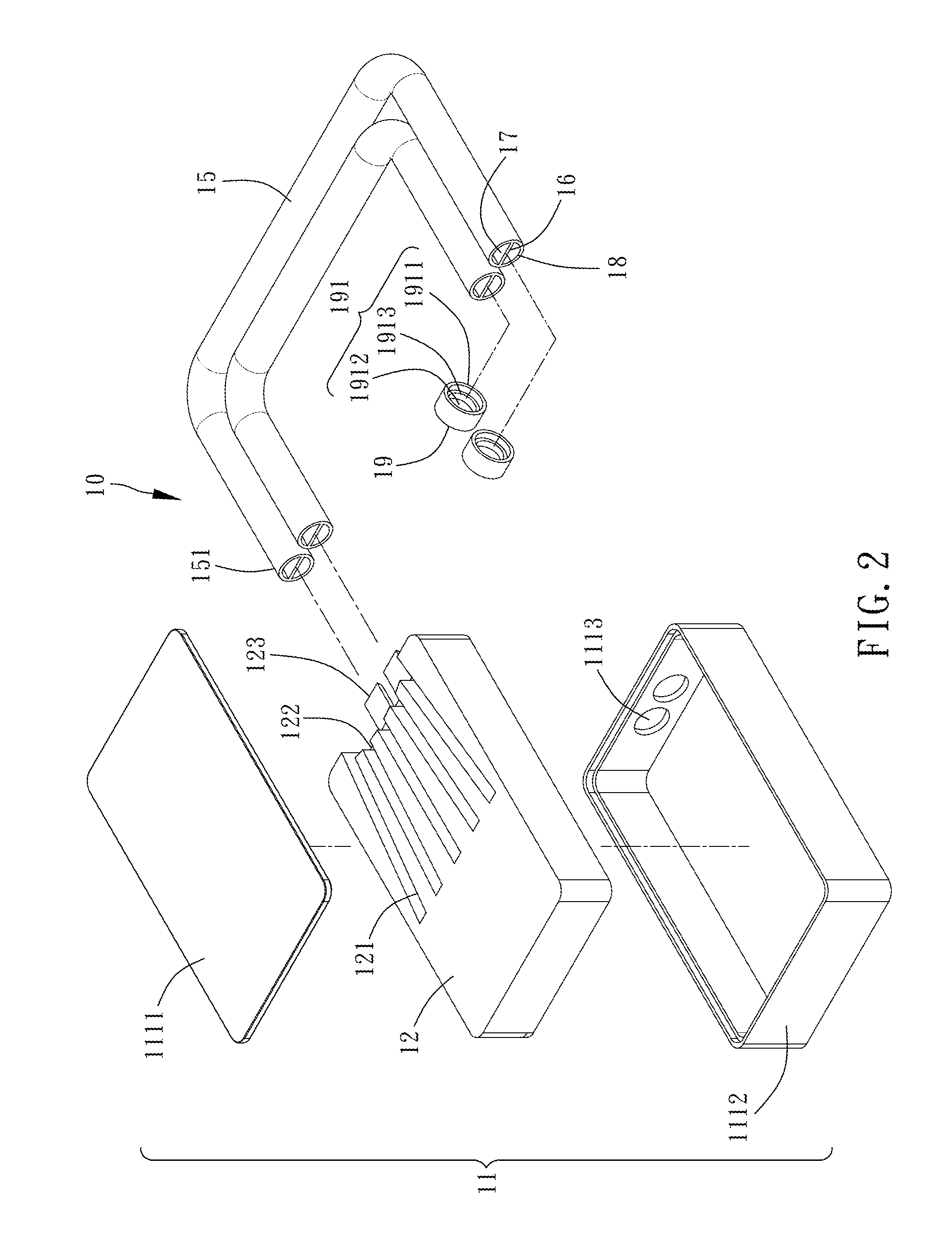
[0007] FIG. 2 is an exploded view of the loop heat pipe of FIG. 1;
[0008] FIG. 3 is a front view of the loop heat pipe of FIG. 1, including a heat-dissipating unit;
[0009] FIG. 4 is a cross-sectional view of the loop heat pipe of FIG. 1;
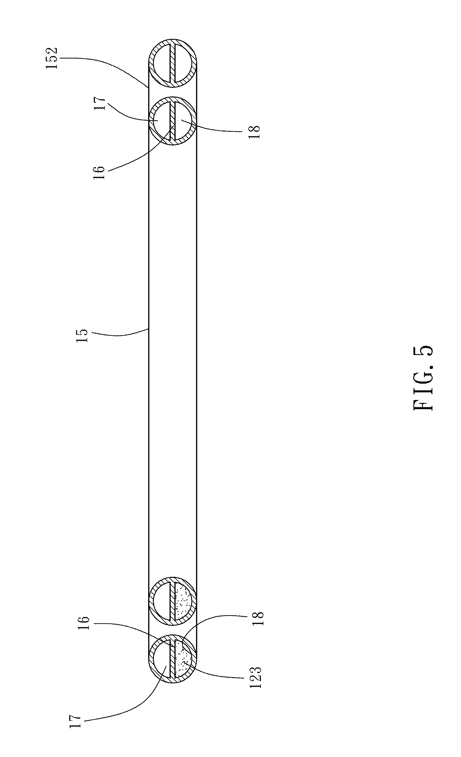
[0010] FIG. 5 is a schematic view of sections of a loop tube of the loop heat pipe of FIG. 1;
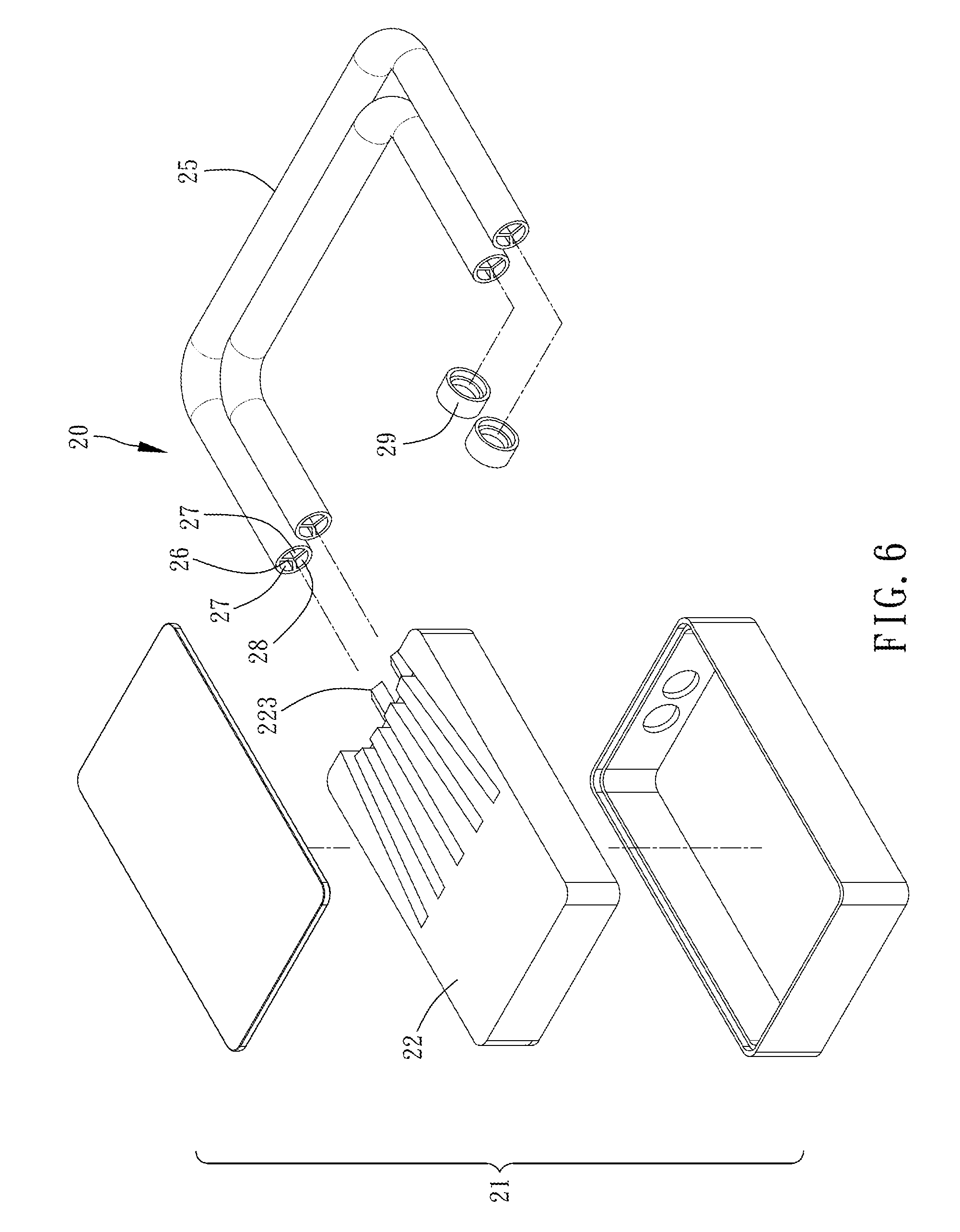
[0011] FIG. 6 is an exploded view of a loop heat pipe according to the second preferred embodiment of the present disclosure;
[0012] FIG. 7 is a cross-sectional view of the loop heat pipe of FIG. 6;
[0013] FIG. 8 is a schematic view of sections of a loop tube of the loop heat pipe of FIG. 6;
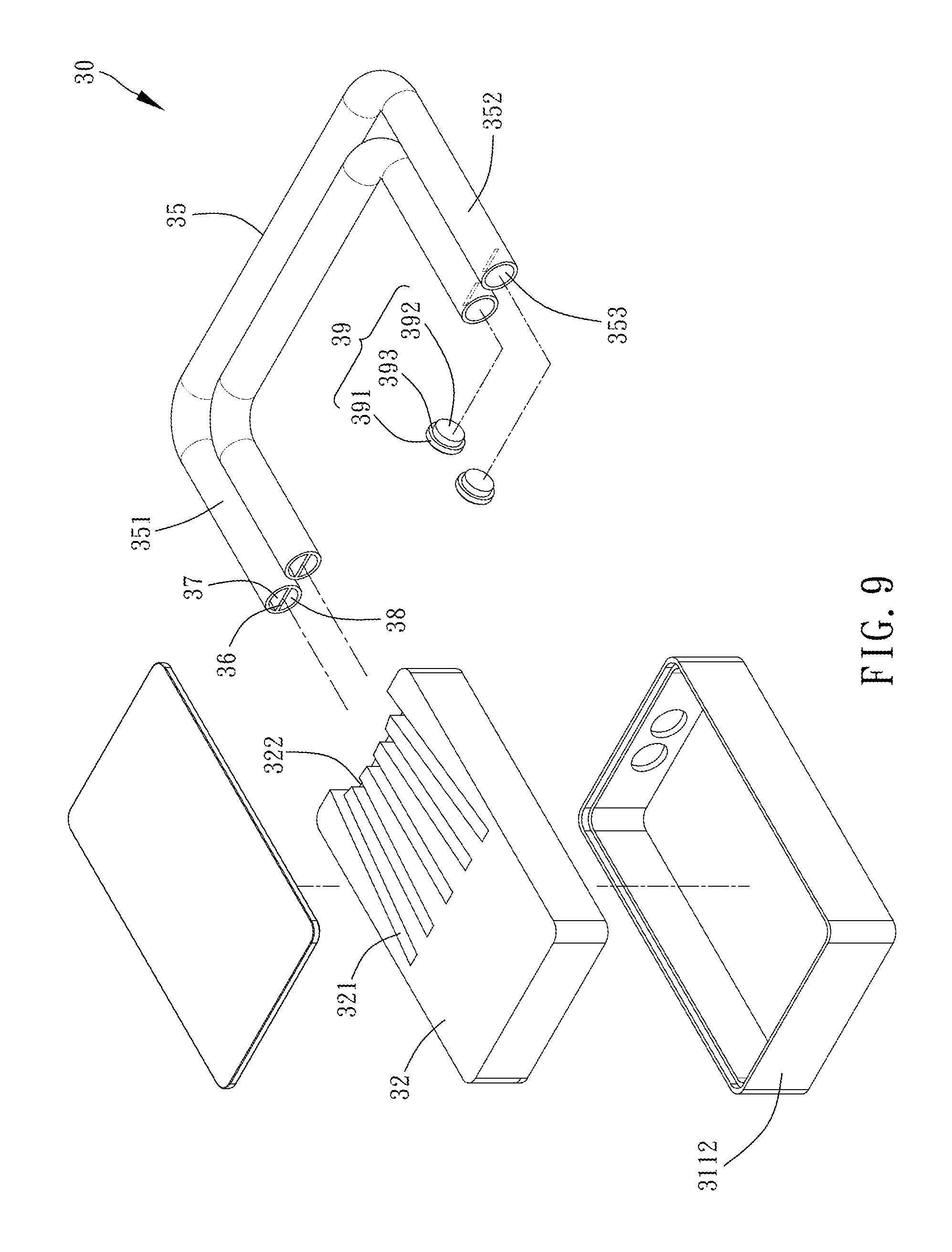
[0014] FIG. 9 is an exploded view of a loop heat pipe according to the third preferred embodiment of the present disclosure;
[0015] FIG. 10 is a cross-sectional view of the loop heat pipe according to the third preferred embodiment of the present disclosure;
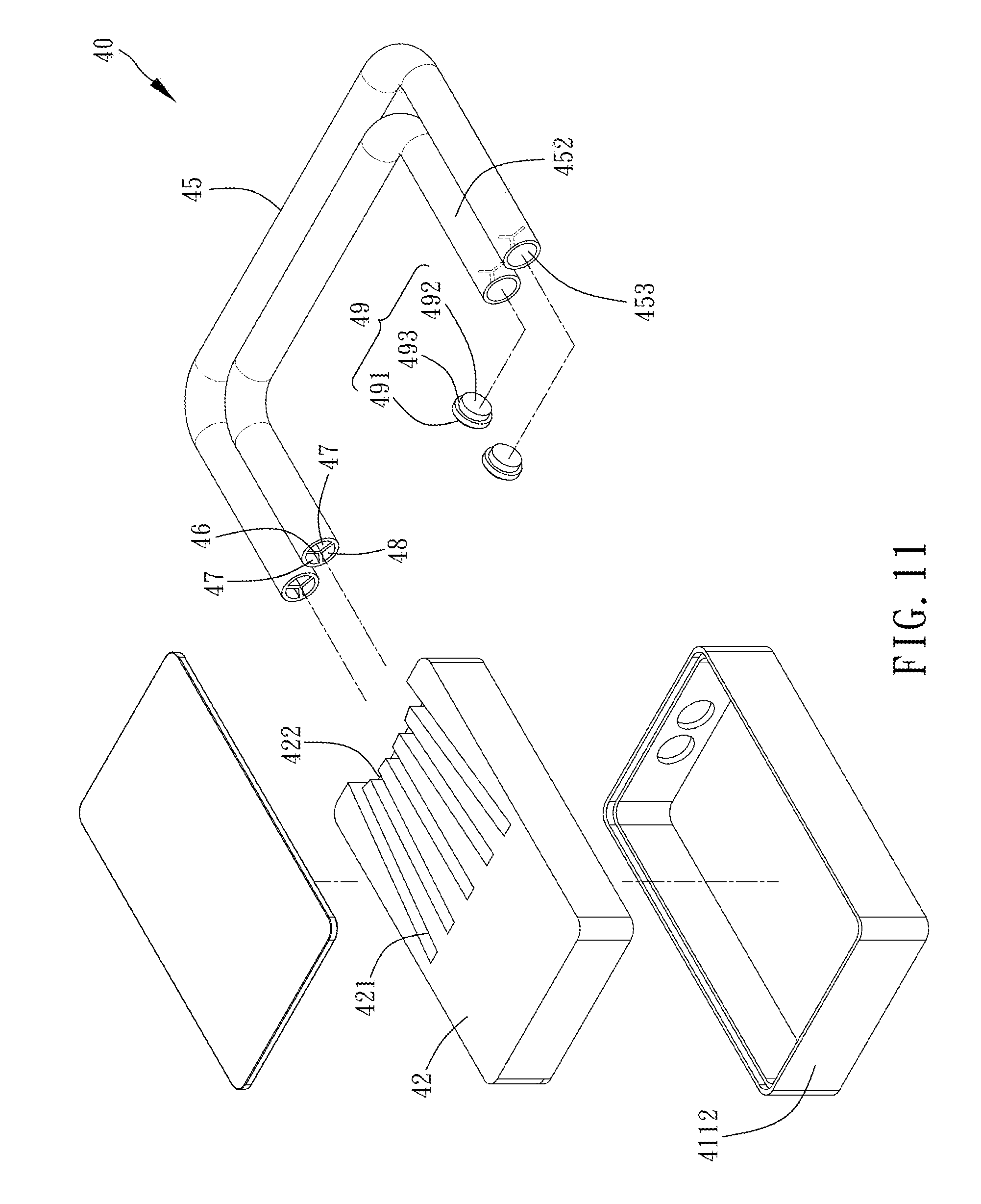
[0016] FIG. 11 is an exploded view of a loop heat pipe according to the fourth preferred embodiment of the present disclosure; and
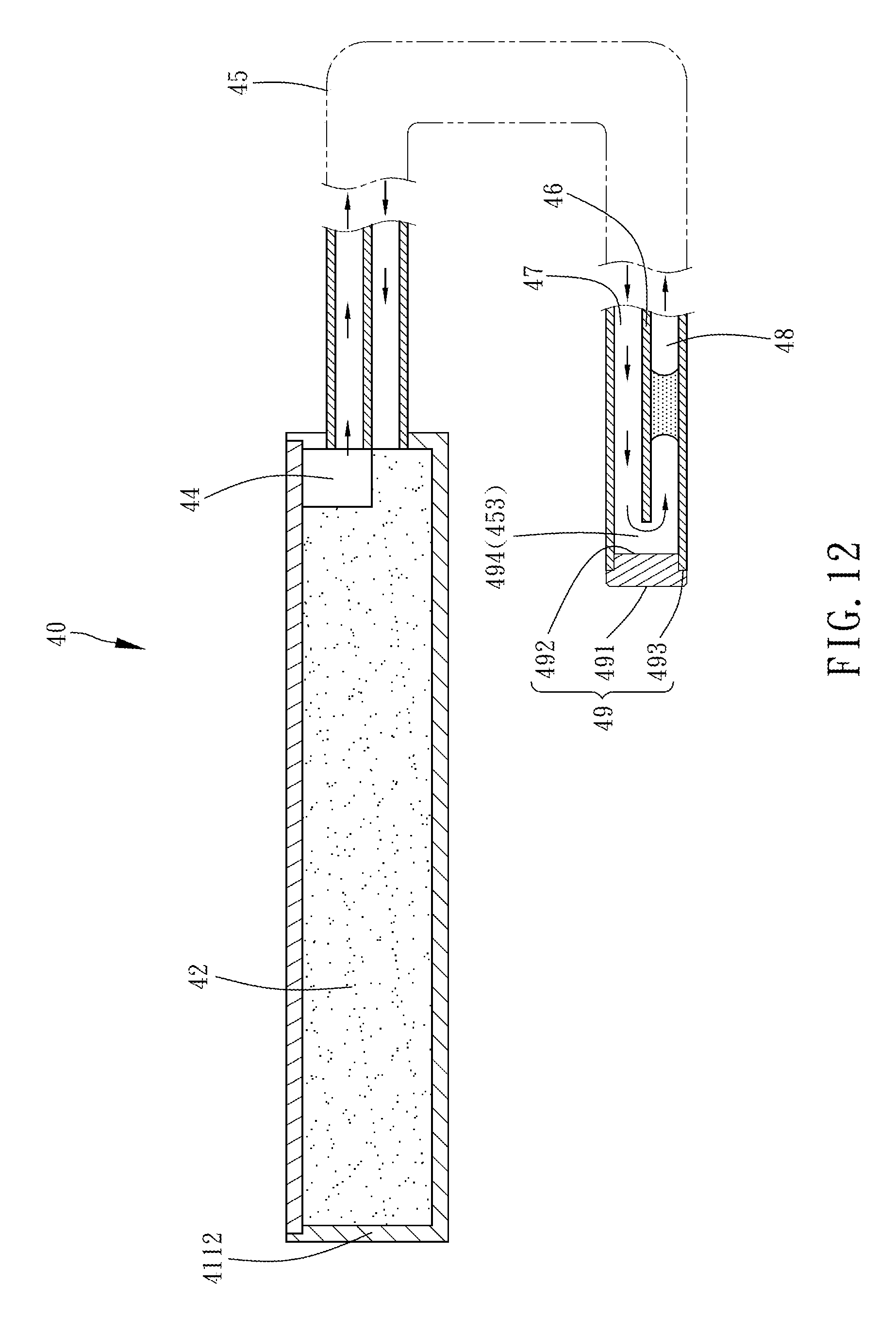
[0017] FIG. 12 is a cross-sectional view of the loop heat pipe according to the fourth preferred embodiment of the present disclosure.
DETAILED DESCRIPTION OF THE INVENTION
[0018] Technical features of the present disclosure are illustrated by preferred embodiments, depicted by drawings, and described below.
[0019] In the first preferred embodiment of the present disclosure, a loop heat pipe 10 partitioned into a vapor channel and a liquid channel essentially comprises an evaporation chamber 11, a loop tube 15, a coupling cover 19 and a heat-dissipating unit 100. All the preferred embodiments described below are exemplified by two loop tubes.
[0020] Referring to FIG. 1 through FIG. 5, the first preferred embodiment of the present disclosure provides the loop heat pipe 10 partitioned into a vapor channel and a liquid channel.
[0021] The evaporation chamber 11 has a casing 111. The casing 111 has therein a wick 12 and is filled with a working fluid 13. The wick 12 does not occupy the inside of the casing 111 fully and thereby an evaporation space 14 is formed between the wick 12 and the casing 111. The casing 111 comprises an upper lid 1111 and a receiving box 1112. The wick 12 is disposed in the receiving box 1112. The upper lid 1111 covers the receiving box 1112. Each side of the receiving box 1112 is defined as a sidewall. Each sidewall has a hole 1113. The holes 1113 and the evaporation space 14 are positioned on the same side of the receiving box 1112 and are in communication with each other. The holes 1113 are penetrable by the loop tubes 15.
[0022] In this embodiment, the wick 12 is made of sintered copper powder and has a plurality of channels 121. The channels 121 each have a channel opening 122 which is in communication with the evaporation space 14. An extending portion 123 extending outward by a predetermined length is disposed on the same side of the wick 12 as the channel openings 122 of the channels 121 are.
[0023] The working fluid 13 in this embodiment is exemplified by pure water that fills the evaporation chamber 11, is adsorbed to the wick 12, and exists at a portion of the loop tubes 15.
[0024] The loop tubes 15 each have two ends defined as a connecting end 151 and an engaging end 152, respectively. The connecting ends 151 are inserted into and engaged with the holes 1113 of the casing 111 and thus are in communication with a space within the casing 111. The loop tubes 15 each have therein a partition element 16. In this embodiment, each partition element 16 is panel-shaped and partitions the corresponding one of the loop tubes 15 into a vapor channel 17 and a liquid channel 18. In each loop tube 15, there is no communication between the vapor channel 17 and the liquid channel 18. In a manufacturing process, the partition element 16 is integrally formed with the loop tube 15. The extending portion 123 of the wick 12 corresponds in shape to the liquid channels 18 of the loop tubes 15. The extending portion 123 is a hemisphere in this embodiment and thus can protrude into the liquid channels 18 by a specific length, so as to block the passage between the evaporation space 14 and the liquid channel 18 and prevent entry of a gaseous working fluid into the liquid channel 18 (as shown in FIG. 5). The extending portion 123 in this embodiment is optional and thus is not restrictive of the present disclosure.
[0025] The coupling cover 19 has a concave portion 191. The concave portion 191 is substantially stepwise and hole-shaped. The concave portion 191 has an opening end 1911 and a bottom end 1912. The opening end 1911 has a larger inner diameter than the bottom end 1912. An annular blocking portion 1913 is formed between the opening end 1911 and the bottom end 1912. When inserted into and engaged with the opening end 1911 of the concave portion 191, the engaging end 152 of the loop tube 15 is blocked by the annular blocking portion 1913 and thus positioned in place; hence, the engaging end 152 of the loop tube 15 is not in contact with the bottom end 1912 of the concave portion 191 of the coupling cover 19. A circulation zone 192 is formed between an end portion of the engaging end 152 of the loop tube 15 and the bottom end 1912 of the concave portion 191 of the coupling cover 19. The vapor channel 17 and the liquid channel 18 within the loop tube 15 become in communication with each other because of the circulation zone 192 as soon as the coupling cover 19 covers and engages with the engaging end 152 of the loop tube 15.
[0026] The heat-dissipating unit 100 is disposed outside the loop tube 15 and positioned proximate to the engaging end 152. In practice, the heat-dissipating unit 100 is a plurality of fins.
[0027] The structure of the loop heat pipe in the first preferred embodiment is described above. The operation of the loop heat pipe in the first preferred embodiment is described below.
[0028] Given the aforesaid structure, before using the loop heat pipe 10, a user places a heat source, such as an electronic device, on the evaporation chamber 11. After operating for a time period, the heat source (not shown) begins to generate heat. The heat thus generated is transferred, by conduction, from the heat source to the evaporation chamber 11 and then to the wick 12. The working fluid 13 is stored in the wick 12 mostly in liquid form. As soon as heat is taken up by the wick 12, the temperature of the wick 12 rises such that a liquid working fluid stored in the wick 12 takes up sufficient heat and thus gradually evaporates into a gaseous working fluid. The gaseous working fluid moves out of the channel openings 122 of the channels 121 of the wick 12 so as to reach and accumulate in the evaporation space 14; afterward, the gaseous working fluid enters the vapor channel 17 of the loop tube 15, moves toward the coupling cover 19, and finally enters the coupling cover 19. The heat from the gaseous working fluid 13 is taken up by the heat-dissipating unit 100 disposed outside the loop tubes 15 and positioned proximate to the engaging end 152 and taken away by air. The gaseous working fluid 13 passing through the condensation segment of the heat-dissipating unit 100 cools and condenses into droplets of the liquid working fluid 13. As time passed, the resultant liquid working fluid 13 in droplets becomes massive enough to form a fluid slug 131 (shown in FIG. 4). The fluid slug 131 is moved under a pressure difference such that the liquid working fluid 13 returns to the evaporation chamber 11 smoothly and easily, so as to enhance heat dissipation efficiency. The aforesaid process recurs and thus guides heat out of the electronic device continuously, thereby performing heat dissipation well.
[0029] Referring to FIG. 6 through FIG. 8, the second preferred embodiment of the present disclosure provides a loop heat pipe 20 partitioned into a vapor channel and a liquid channel. The second preferred embodiment is substantially identical to the first preferred embodiment except for the distinguishing technical features described below.
[0030] A loop tube 25 has therein three partition elements 26 arranged to jointly form a V-shaped pattern when viewed from a sectional perspective. The three partition elements 26 partition the loop tube 25 into two vapor channels 27 and one liquid channel 28. In the loop tube 25, the two vapor channels 27 and the liquid channel 28 are not in communication with each other. In a manufacturing process, the three partition elements 26 are not only integrally formed, but are also integrally formed with the loop tube 25.
[0031] A wick 22 has an extending portion 223 corresponding in position to the liquid channel 28 of the loop tube 25. In this embodiment, the extending portion 223 is fan-shaped and thus can protrude into the liquid channel 28 by a specific length, so as to block the passage between an evaporation space 24 and the liquid channel 28 and prevent entry of a gaseous working fluid into the liquid channel 28 (as shown in FIG. 8). The extending portion 223 in this embodiment is optional and thus is not restrictive of the present disclosure.
[0032] The three partition elements 26 partition the loop tube into two vapor channels 27 and one liquid channel 28. The liquid working fluid 13 in the liquid channel 28 forms the fluid slug 131. The fluid slug 131 is moved under a pressure difference such that the liquid working fluid 13 returns to the evaporation chamber 21 smoothly, so as to enhance heat dissipation efficiency.
[0033] The other structural features and achievable advantages of the second preferred embodiment are substantially identical to those of the first preferred embodiment and thus, for the sake of brevity, are not described herein.
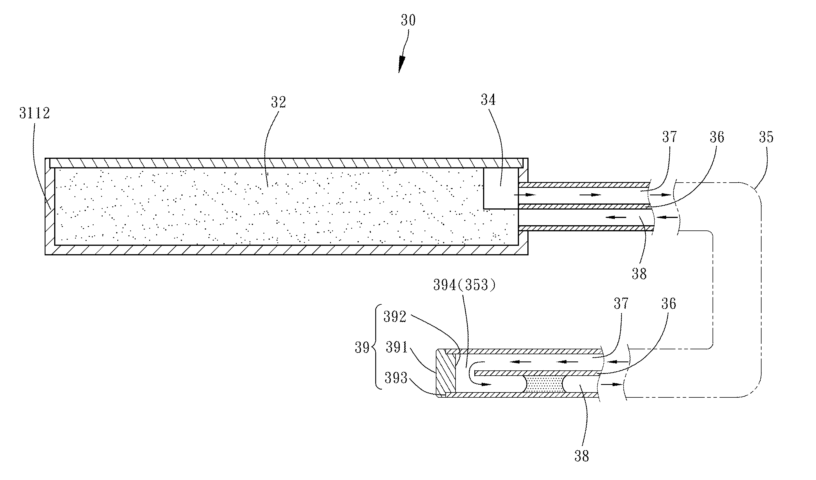
[0034] Referring to FIG. 9 and FIG. 10, the third preferred embodiment of the present disclosure provides a loop heat pipe 30 partitioned into a vapor channel and a liquid channel. The third preferred embodiment is substantially identical to the first preferred embodiment except for the distinguishing technical features described below.
[0035] In this embodiment, a partition element 36 is panel-shaped and partitions a loop tube 35 into a vapor channel 37 and a liquid channel 38. The loop tube 35 has a connecting end 351 and an engaging end 352. The partition element 36 is of a smaller length than the loop tube 35, extends from the connecting end 351 to the engaging end 352 of the loop tube 35, and forms a retracted space 353 together with an end portion of the engaging end 352. A coupling cover 39 has a bottom portion 391 of a large diameter, a top portion 392 of a small diameter, and an annular blocking portion 393 formed between the bottom portion 391 and the top portion 392. The top portion 392 of the coupling cover 39 is inserted into and engaged with the retracted space 353 at the engaging end 352; hence, not only is a circulation zone 394 formed between the top portion 392 of the coupling cover 39 and the retracted space 353, but the end portion of the engaging end 352 of the loop tube 35 is also blocked by the annular blocking portion 393 and thus positioned in place.
[0036] A wick 32 is disposed in a receiving box 3112 and has a plurality of channels 321 (but the wick 32 does not have any extending portion). Channel openings 322 of the channels 321 are in communication with an evaporation space 34.
[0037] The other structural features and achievable advantages of the third preferred embodiment are substantially identical to those of the first preferred embodiment and thus, for the sake of brevity, are not described herein.
[0038] Referring to FIG. 11 and FIG. 12, the fourth preferred embodiment of the present disclosure provides a loop heat pipe 40 partitioned into a vapor channel and a liquid channel. The fourth preferred embodiment is substantially identical to the first preferred embodiment except for the distinguishing technical features described below.
[0039] A loop tube 45 has therein three partition elements 46 arranged to jointly form a V-shaped pattern when viewed from a sectional perspective. The three partition elements 46 partition the loop tube 45 into two vapor channels 47 and one liquid channel 48. The partition elements 46 are of a smaller length than the loop tube 45 such that a retracted space 453 is formed at an end portion of an engaging end 452 of the loop tube 45. A coupling cover 49 has a bottom portion 491 of a large diameter, a top portion 492 of a small diameter, and an annular blocking portion 493 formed between the bottom portion 491 and the top portion 492. The top portion 492 of the coupling cover 49 is inserted into and engaged with the retracted space 453 at the engaging end 452; hence, not only is a circulation zone 494 formed between the top portion 492 and the retracted space 453, but an end portion of the engaging end 452 of the loop tube 45 is also blocked by the annular blocking portion 493 and thus positioned in place.
[0040] A wick 42 is disposed in a receiving box 4112 and has a plurality of channels 421 (but the wick 42 does not have any extending portion). Channel openings 422 of the channels 421 are in communication with an evaporation space 44.
[0041] The other structural features and achievable advantages of the fourth preferred embodiment are substantially identical to those of the first preferred embodiment and thus, for the sake of brevity, are not described herein.
[0042] Therefore, in the aforesaid preferred embodiments of the present disclosure, the loop tube 15 has therein the partition element 16 and thereby is partitioned into the vapor channel 17 and the liquid channel 18. The coupling cover 19 is coupled to an end of the loop tube 15, so as to form the circulation zone 192 whereby the vapor channel 17 and the liquid channel 18 are in communication with each other. Compared with the prior art, the present disclosure provides the coupling cover 19 which is structurally simple, dispenses with the need to change the shape of pipes, and reduces manufacturing costs.
* * * * *
D00000
D00001
D00002
D00003
D00004
D00005
D00006
D00007
D00008
D00009
D00010
D00011
D00012
XML
uspto.report is an independent third-party trademark research tool that is not affiliated, endorsed, or sponsored by the United States Patent and Trademark Office (USPTO) or any other governmental organization. The information provided by uspto.report is based on publicly available data at the time of writing and is intended for informational purposes only.
While we strive to provide accurate and up-to-date information, we do not guarantee the accuracy, completeness, reliability, or suitability of the information displayed on this site. The use of this site is at your own risk. Any reliance you place on such information is therefore strictly at your own risk.
All official trademark data, including owner information, should be verified by visiting the official USPTO website at www.uspto.gov. This site is not intended to replace professional legal advice and should not be used as a substitute for consulting with a legal professional who is knowledgeable about trademark law.