Ice Maker and Refrigerator Having Same
YANG; Sung Jin
U.S. patent application number 16/388702 was filed with the patent office on 2019-10-31 for ice maker and refrigerator having same. The applicant listed for this patent is Daewoo Electronics Corporation. Invention is credited to Sung Jin YANG.
| Application Number | 20190331388 16/388702 |
| Document ID | / |
| Family ID | 68292306 |
| Filed Date | 2019-10-31 |


| United States Patent Application | 20190331388 |
| Kind Code | A1 |
| YANG; Sung Jin | October 31, 2019 |
Ice Maker and Refrigerator Having Same
Abstract
The present invention relates to an ice maker and a refrigerator having the same. According to one aspect of the present invention, the refrigerator may include a main body having a storage room; a door on the main body to open and close the storage room; and an ice maker in the storage room. The ice maker includes an ice tray to contain water; a guide unit under the ice tray to form a path for flowing cold air; an ice bucket under the guide unit and including a container having a center portion that is concave downwards; and a rotation unit configured to move the ice in the ice tray to the ice bucket. The rotation unit includes a gear configured to transfer a driving force of a driving motor; and an ice removing shaft configured to receive the driving force of the gear and rotate, the ice removing shaft having a coupling unit in the gear, the coupling unit having a back end with a cross-sectional area larger than that of a front end of the coupling unit.
| Inventors: | YANG; Sung Jin; (Incheon, KR) | ||||||||||
| Applicant: |
|
||||||||||
|---|---|---|---|---|---|---|---|---|---|---|---|
| Family ID: | 68292306 | ||||||||||
| Appl. No.: | 16/388702 | ||||||||||
| Filed: | April 18, 2019 |
| Current U.S. Class: | 1/1 |
| Current CPC Class: | F25C 5/22 20180101; F25C 2500/02 20130101; F25C 5/04 20130101 |
| International Class: | F25C 5/20 20060101 F25C005/20 |
Foreign Application Data
| Date | Code | Application Number |
|---|---|---|
| Apr 26, 2018 | KR | 10-2018-0048728 |
Claims
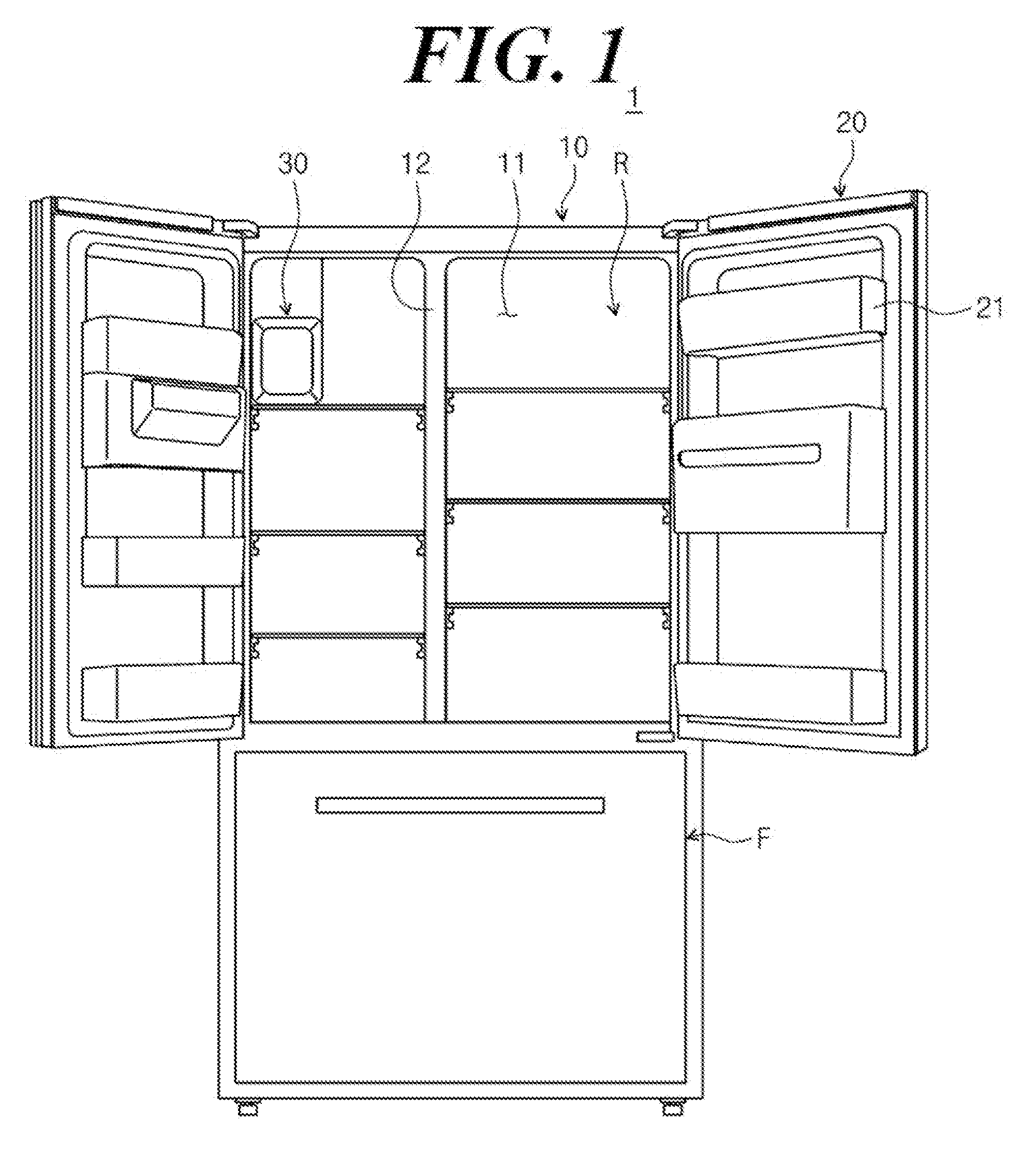
1. A refrigerator comprising: a main body having a storage room therein; a door on the main body, configured to open and close the storage room; and an ice maker in the storage room, wherein the ice maker includes: an ice tray configured to contain water; a guide unit under the ice tray, forming a path for flowing cold air; an ice bucket under the guide unit, comprising a container having a center portion that is concave downwards; and a rotation unit configured to move the ice in the ice tray to the ice bucket, wherein the rotation unit includes: a gear configured to transfer a driving force from a driving motor; and an ice removing shaft configured to receive the driving force of the gear and rotate, wherein the ice removing shaft includes a coupling unit in the gear, the coupling unit having a front end and a back end, and the back end has a cross-sectional area larger than that of the front end.
2. The refrigerator according to claim 1, wherein the gear includes a coupling hole configured to receive the ice removing shaft, and the coupling unit includes a multi-stage shape having a first portion, stage or section and a second portion, stage or section in the coupling hole.
3. The refrigerator according to claim 2, wherein the second portion, stage or section has a cross-sectional area corresponding to the coupling hole, and the first portion, stage or section has a cross-sectional area smaller than that of the second portion, stage or section.
4. The refrigerator according to claim 3, wherein each of the coupling hole, the first portion, stage or section and the second portion, stage or section have a D shape.
5. The refrigerator according to claim 3, wherein each of the coupling hole, the first portion, stage or section and the second portion, stage or section have a V shape or nearly a V shape.
6. The refrigerator according to claim 3, wherein the coupling unit comprises a step between the first portion, stage or section and the second portion, stage or section.
7. An ice maker, comprising: a case; an ice making assembly in the case and configured to make ice; and an ice bucket configured to contain the ice from the ice making assembly, wherein the ice making assembly includes: an ice tray configured to contain water; a guide unit configured to form a path for flowing cold air; and a rotation unit configured to move the ice in the ice tray to the ice bucket, wherein the rotation unit includes: an ice removing shaft on or above the ice tray, having an end with a multi-stage shape; and a gear coupled to the ice removing shaft, wherein the gear includes a coupling hole corresponding to the multi-stage shape of the ice removing shaft.
8. The ice maker according to claim 7, wherein a portion, stage or section of the multi-stage shape has an area corresponding to the coupling hole.
9. The ice maker according to claim 8, wherein the coupling hole and the portion, stage or section of the multi-stage shape have a D shape.
10. The ice maker according to claim 8, wherein the coupling hole and the portion, stage or section of the multi-stage shape have a V shape or nearly a V shape.
11. The ice maker according to claim 8, wherein the multi-stage shape includes a step.
Description
TECHNICAL FIELD
[0001] The present invention relates to an ice maker and a refrigerator having the same.
BACKGROUND
[0002] A refrigerator is an apparatus for storing food at a low temperature. The refrigerator can be configured to store the food in a frozen or refrigerated state, according to the type of food to be stored. The inside of the refrigerator is cooled down by continuously supplied cold air, and the cold air is continuously generated by the heat exchange action of a refrigerant by way of a refrigeration cycle going through the process of compression, condensation, expansion and evaporation. Since the cold air supplied to the inside of the refrigerator is evenly delivered inside the refrigerator owing to convection, the food inside the refrigerator can be stored at a desired temperature.
[0003] An ice maker may be provided in the refrigerator for the convenience of use. The ice maker may make ice by supplying cold air to water and storing a predetermined amount of ice. The ice maker may include an ice making tray for making ice, an ice storage unit for storing the ice made by the ice making tray, and a cover unit for protecting the ice making tray.
SUMMARY
[0004] An object of the present invention is to provide an ice maker that is easy to assemble, and a refrigerator having the same.
[0005] In addition, another object of the present invention is to provide an ice maker with enhanced coupling force, and a refrigerator having the same.
[0006] In accordance with an aspect of the present invention, there is provided a refrigerator comprising a main body having a storage room therein; a door on the main body, configured to open and close the storage room; and an ice maker in the storage room, wherein the ice maker includes an ice tray configured to contain water; a guide unit under the ice tray, forming a path for flowing cold air; an ice bucket under the guide unit, comprising a container having a center portion that is concave downwards; and a rotation unit configured to move the ice in the ice tray to the ice bucket, wherein the rotation unit includes a gear configured to transfer a driving force from a driving motor; and an ice removing shaft configured to receive the driving force from the gear and rotate, wherein the ice removing shaft includes a coupling unit in the gear, the coupling unit having a front end and a back end, the back end having a cross-sectional area (e.g., perpendicular to a length direction of the ice removing shaft) that is larger than that of the front end.
[0007] The gear may include a coupling hole configured to receive the ice removing shaft, and the coupling unit may include a multi-stage shape having a first portion, stage or section and a second portion, stage or section in the coupling hole.
[0008] The second portion, stage or section may have an area corresponding to the coupling hole, and the first portion, stage or section may have an area smaller than that of the second portion.
[0009] The coupling hole, the first portion, stage or section and the second portion, stage or section may each have a D-cut processed shape (e.g., a D shape).
[0010] Alternatively, the coupling hole, the first portion, stage or section and the second portion, stage or section may each have a V-cut processed shape (e.g., a V shape or nearly a V shape).
[0011] The coupling unit may include a step between the first portion, stage or section and the second portion, stage or section, and the step may be small or gentle.
[0012] In accordance with an aspect of the present invention, there is provided an ice maker (e.g., for a refrigerator or to be installed in the refrigerator and configured to make ice), the ice maker comprising a case; an ice making assembly in the case, configured to make ice; and an ice bucket configured to contain the ice from the ice making assembly, wherein the ice making assembly includes an ice tray configured to contain water; a guide unit forming a path for flowing cold air; and a rotation unit configured to move the ice in the ice tray to the ice bucket, wherein the rotation unit includes an ice removing shaft on or above the ice tray, having one end with a multi-stage shape; and a gear that may be directly coupled to the ice removing shaft, wherein the gear includes a coupling hole corresponding to the multi-stage shape of the ice removing shaft.
[0013] A portion, stage or section of the multi-stage shape may have an area corresponding to the coupling hole.
[0014] The coupling hole and the multi-stage shape portion may have a D-cut processed shape (e.g., a D shape).
[0015] Alternatively, the coupling hole and the multi-stage shape portion may have a V-cut processed shape (e.g., a V shape or nearly a V shape).
[0016] The multi-stage shape portion, stage or section may have a step (e.g., between adjacent stages or sections) that is small or gentle.
[0017] According to embodiments of the present invention, an ice maker easy to assemble and a refrigerator having the same may be provided.
[0018] In addition, an ice maker with enhanced coupling force and a refrigerator having the same may be provided.
BRIEF DESCRIPTION OF THE DRAWINGS
[0019] FIG. 1 is a perspective view showing an exemplary refrigerator according to one or more embodiments of the present invention;
[0020] FIG. 2 is a perspective view showing an exemplary ice maker;
[0021] FIG. 3 is an exploded perspective view showing the ice maker of FIG. 2;
[0022] FIG. 4 is a side cross-sectional view showing the ice maker of FIG. 2;
[0023] FIG. 5 is a perspective view showing the ice making assembly in FIG. 3, without a cover unit;
[0024] FIG. 6 is a side cross-sectional view showing the ice making assembly of FIG. 5;
[0025] FIG. 7 is an exploded perspective view of the gear and the ice removing shaft shown in FIG. 6;
[0026] FIG. 8 is an exploded perspective view showing an exemplary gear and ice removing shaft according to an alternative embodiment of the present invention;
DETAILED DESCRIPTION
[0027] Hereafter, embodiments of the present invention will be described in more detail with reference to the accompanying drawings. The disclosed embodiments may be modified in a variety of forms, and the scope of the present invention should not be limited to the embodiments described below. The embodiments are provided to explain the present invention to those skilled in the art. Accordingly, the shapes of the elements in the drawing may be exaggerated to emphasize more clear descriptions.
[0028] FIG. 1 is a perspective view showing a refrigerator according to an embodiment of the present invention.
[0029] Referring to FIG. 1, a refrigerator 1 according to one or more embodiments of the present invention may include a main body 10 and one or more doors 20.
[0030] Hereinafter, the direction from the rear side to the front side of the refrigerator 1 is referred to as a thickness direction, the direction from one side surface to another side surface of the refrigerator 1 is referred to as a width direction, and the direction from the bottom surface to the top surface of the refrigerator 1 is referred to as a height direction. The door(s) 20 are at the front of the refrigerator 1, and the icemaker 30 is adjacent to the top surface of the refrigerator 1.
[0031] The main body 10 provides the overall external shape of the refrigerator 1. At least one storage room 11 may be inside the main body 10. The storage room(s) 11 inside the main body 10 may be partitioned by a barrier 12. The storage room 11 may include a refrigeration room R and a freezer room F. For example, the refrigeration room R may be at or in the upper part of the main body 10, and the freezer room F may be at or in the lower part of the main body 10.
[0032] At least one door 20 is on the main body 10. The door 20 opens and closes the storage room 11. For example, the door 20 is hingedly or pivotally fixed to the main body 10 to rotate, and may open and close the storage room 11 as it rotates with respect to the main body 10. The number of doors 20 may correspond to the number of storage rooms 11. For example, doors 20 are provided in front of the refrigeration room(s) R and the freezer room(s) F, respectively, and may individually open and close a corresponding one of the refrigeration room(s) R and the freezer room(s) F. For example, two doors 20 may be provided for the refrigeration rooms R on the left and right sides of the refrigerator 1. One or more shelves 21 may be provided on the inside surface of the door 20.
[0033] An ice maker 30 may be at one side of one storage room 11. For example, the ice maker 30 may be in one refrigeration room R and/or at the upper part of one of the storage rooms 11. Alternatively, the ice maker 30 may be in one door 20 or in the freezer room F.
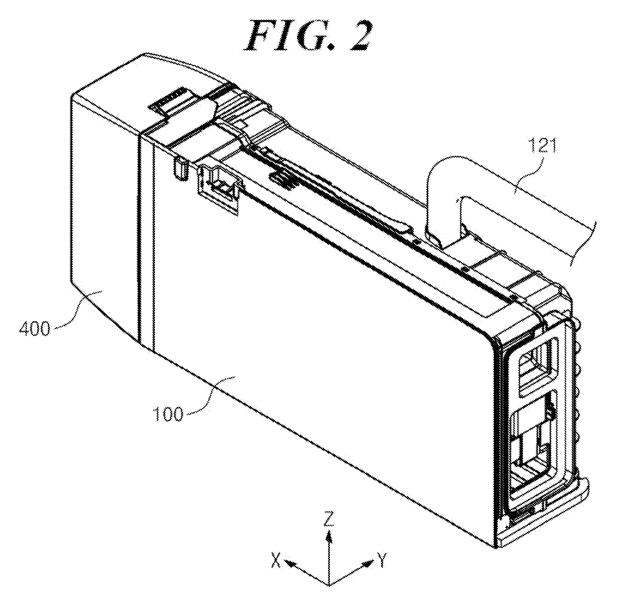
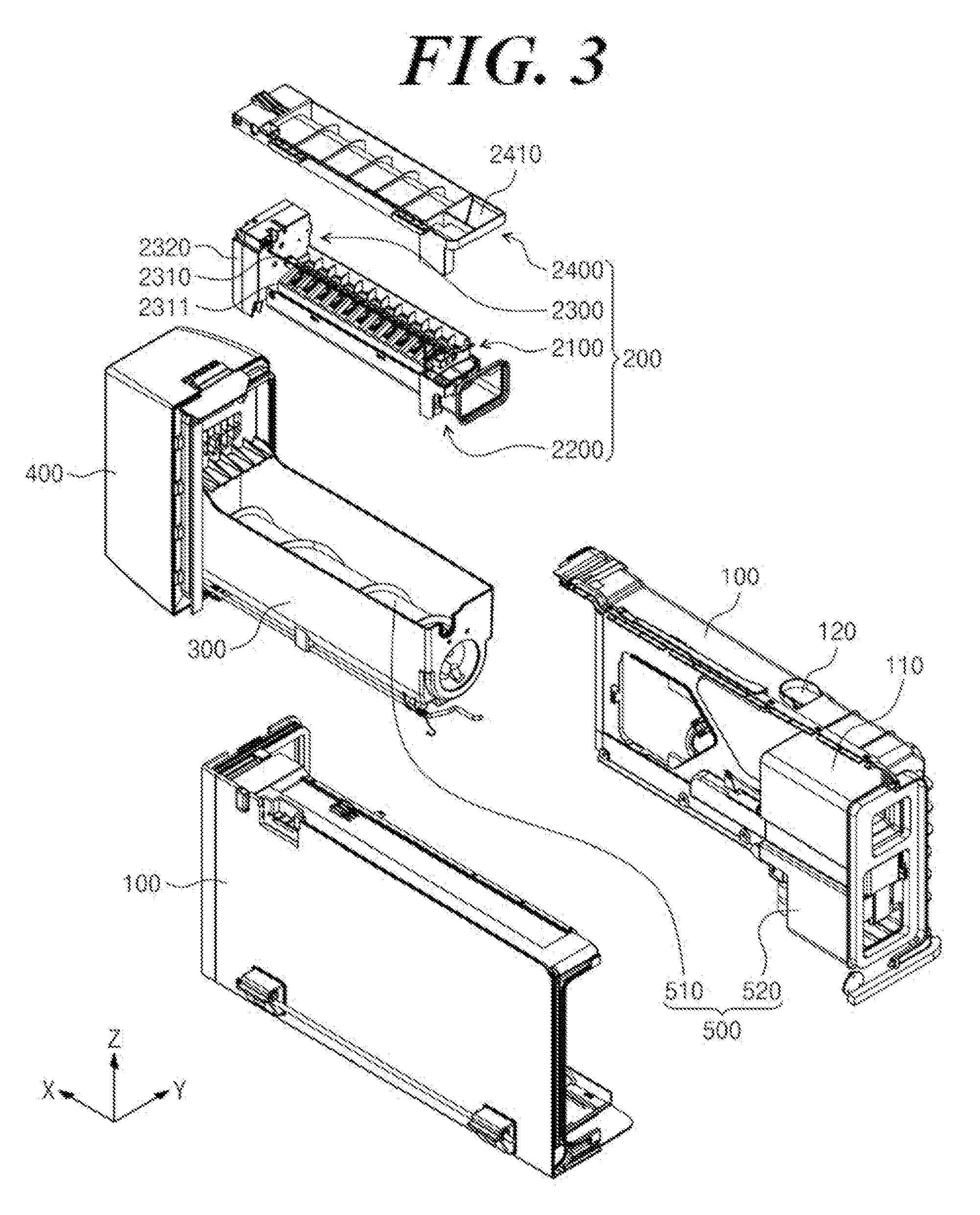
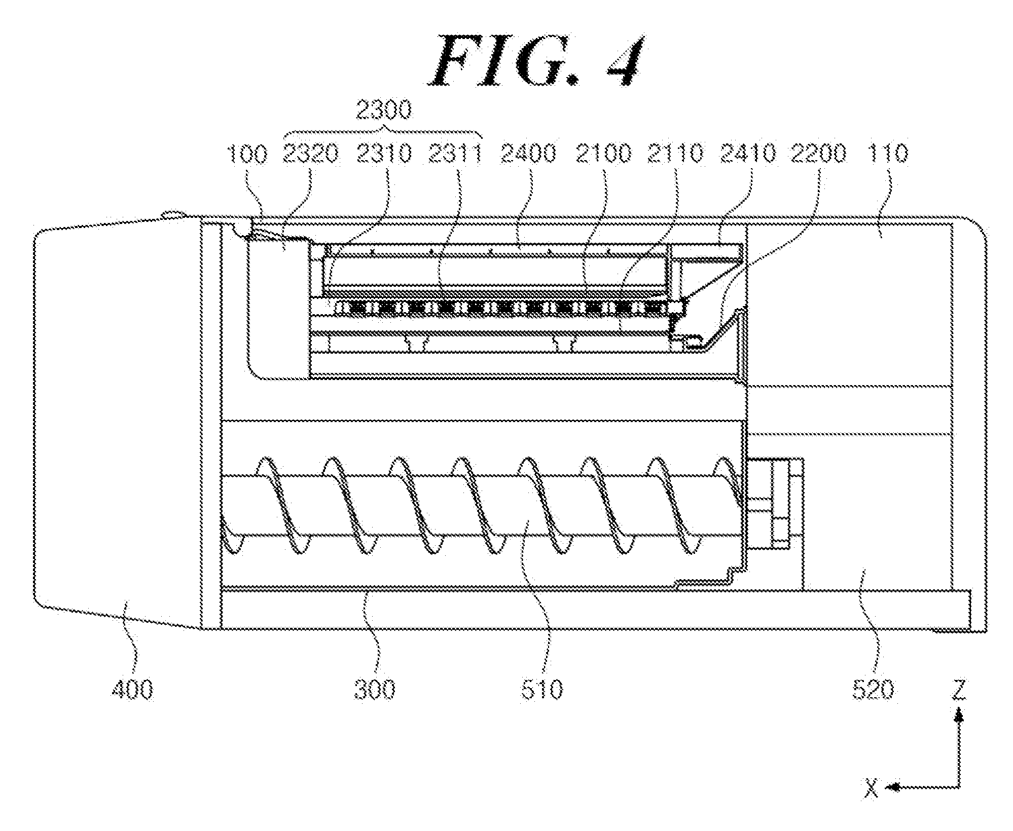
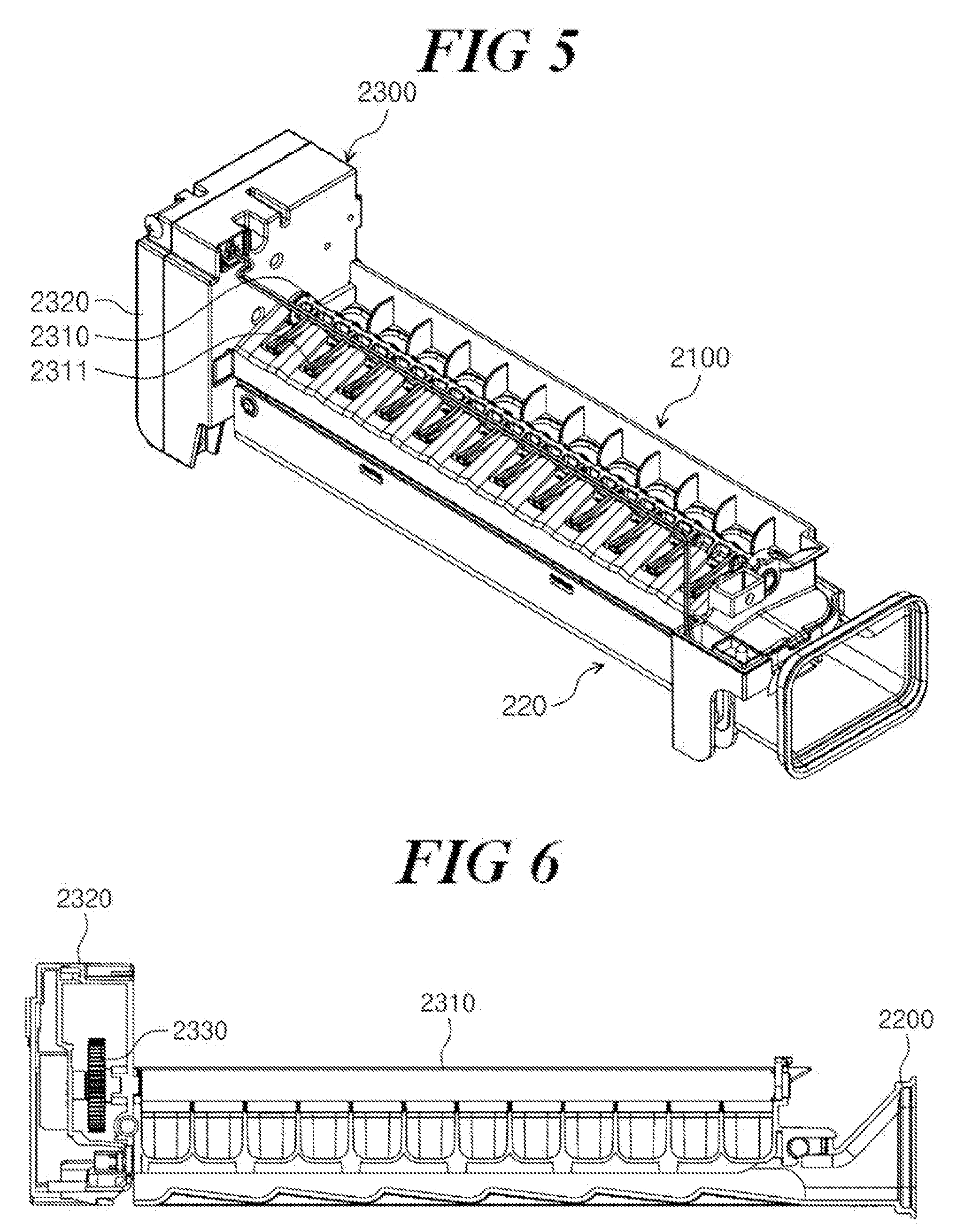
[0034] FIG. 2 is a perspective view showing an exemplary ice maker suitable for the refrigerator 1 of FIG. 1, FIG. 3 is an exploded perspective view showing the ice maker of FIG. 2, FIG. 4 is a side cross-sectional view showing the ice maker of FIG. 2, FIG. 5 is a perspective view showing the ice making assembly in the ice maker of FIG. 2 without a cover unit, FIG. 6 is a side cross-sectional view showing the ice making assembly of FIG. 5, and FIG. 7 is an exploded perspective view showing the exemplary gear and exemplary ice removing shaft of the ice making assembly of FIG. 6.
[0035] Referring to FIGS. 2 to 6, the ice maker 30 may include a case 100, an ice making assembly 200, an ice bucket 300, a discharge unit 400 and a transfer unit 500.
[0036] The ice maker 30 may make and store ice.
[0037] Hereinafter, the direction from a cold air duct 110 to the discharge unit 400 is referred to as a first direction X, a direction perpendicular to the first direction X (e.g., a horizontal direction and/or in a plane) is referred to as a second direction Y, and the vertical direction perpendicular to both the first direction X and the second direction Y is referred to as a third direction Z. In addition, a side on which the discharge unit 400 is located is referred to as a front side (e.g., of the ice maker), and a side on which the cold air duct 110 is located is referred to as a rear side (e.g., of the ice maker).
[0038] The external shape of the ice maker 30 may be defined in part by the case 100. The case 100 may have a preset volume and a space for accommodating constitutional components of the ice maker 30 therein. The case 100 may be fixed at a point inside the storage room 11 or inside the door 20. In addition, a first latching unit (not shown), a second latching unit (not shown) and a flap holder (not shown) configured to couple the case 100 to the discharge unit 400 may be in or on the case 100. The specific coupling of the case 100 and the discharge unit 400 will be described below.
[0039] The ice making assembly 200 may make ice by exchanging heat of water contained in the ice making assembly 200 with cold air. The ice making assembly 200 may include an ice tray 2100, a guide unit 2200, a rotation unit 2300 and a cover unit 2400.
[0040] The ice tray 2100 is configured to contain water. The water in the ice tray 2100 is solidified (i.e., becomes ice) through heat exchange with cold air. The ice tray 2100 may comprise a container, having a center portion that is concave downwards (see, e.g., the cross-section of FIG. 6), and a space and/or preset volume for containing water may be on or in the ice tray 2100. For example, the ice tray 2100 may comprise a multi-compartment container, each compartment being configured to hold a predetermined volume of liquid water and optionally having a convex lower surface, in which the center of each compartment has a greater depth than along the sidewalls of each compartment. The ice tray 2100 may have a preset length along the first direction X and a preset width in the second direction Y. For example, the ice tray 2100 may be rectangular as seen from the top.
[0041] A heater 2110 may be under the ice tray 2100. The heater 2110 may contact the bottom surface of the ice tray 2100 at least at one point, and up to substantially the entire bottom surface of the ice tray 2100. When the ice made in the ice tray 2100 is transferred to the ice bucket 300 by the rotation unit 2300, the heater 2110 may heat the bottom surface of the ice tray 2100 so that the ice may be effectively separated from the ice tray 2100.
[0042] The guide unit 2200 may be under the ice tray 2100. The guide unit 2200 forms a path for flowing cold air onto and/or around the ice tray 2100. The cold air flowing between the guide unit 2200 and the ice tray 2100 cools down the ice tray 2100 to freeze the water in the ice tray 2100. The guide unit 2200 may have a preset length in the first direction X and a preset width in the second direction Y. The guide unit 2200 may contact the ice tray 2100 at least at a point and may support the ice tray 2100. The rear end of the guide unit 2200 in the first direction X may communicate with the cold air duct 110 which supplies the cold air. The guide unit 2200 may be fixed to the inside surface of the case 100 or to the cold air duct 110.
[0043] The rotation unit 2300 moves the ice in the ice tray 2100 to the ice bucket 300. The rotation unit 2300 may include an ice removing shaft 2310, a drive housing 2320, and a gear 2330.
[0044] As the ice removing shaft 2310 rotates, the ice in the ice tray 2100 is moved to the outside of the ice tray 2100. The ice removing shaft 2310 has a preset length and may be in a space above the ice tray 2100. The length of the ice removing shaft 2310 may be in or along the first direction X. One or more ice removing prominences 2311 may be along the ice removing shaft 2310. The ice removing prominence(s) 2311 may extend from the outer surface of the ice removing shaft 2310 by a preset length. The ice removing prominence(s) 2311 may not contact the water in the ice tray 2100 when the rotation unit 2300 is in a standby state (i.e., not in an operational state). When the ice removing shaft 2310 rotates for transfer of the ice, the ice removing prominence(s) 2311 may push the ice out of the ice tray 2100.
[0045] The ice removing shaft 2310 may include a coupling unit 2312 at one end or side. The coupling unit 2312 couples to the gear 2330 and is on the drive housing 2320 side (e.g., of the ice maker). The coupling unit 2312 may have a form or shape corresponding to that of the coupling hole 2331 in the gear 2330.
[0046] The coupling unit 2312 may have a preset length along the first direction X and may have, in part, a circular cross section. One side or section (e.g., along the circumference) of the coupling unit 2312 may have a tolerance.
[0047] The coupling unit 2312 may have a back end or section with a cross-sectional area (e.g., in a plane perpendicular to the length direction) that is larger than that of a front end or section of the coupling unit 2312. For example, the coupling unit 2312 may have a multi-stage shape, and sections, stages or portions of the multi-stage shape may correspond to the coupling hole 2331. Specifically, the coupling unit 2312 may have a first portion 2312a and a second portion 2312b, and the first portion 2312a and the second portion 2312b may be tolerance parts in the coupling unit 2312. In addition, the first portion 2312a and the second portion 2312b may have different dimensions. The second portion 2312b may be relatively close to the ice removing prominence(s) 2311 as compared with the first portion 2312a and may have a smaller planar surface area than the first portion 2312a and a larger cross-sectional area than the first portion 2312a in the plane perpendicular to the length direction.
[0048] As the first portion 2312a and the second portion 2312b have different dimensions, a step may result between the first portion 2312a and the second portion 2312b. The step between the first portion 2312a and the second portion 2312b may be small and/or gentle.
[0049] The first portion 2312a and the second portion 2312b may directly contact the gear 2330, and accordingly, the first portion 2312a and the second portion 2312b may be inside the drive housing 2320. Coupling of the coupling unit 2312 and the gear 2330 will be described below.
[0050] A drive unit (e.g., motor) inside the drive housing 2320 provides power for rotating the ice removing shaft 2310. The drive housing 2320 may be located at one side of the ice tray 2100 along or with respect to the first direction X. The drive housing 2320 may be located on the opposite side of the ice removing shaft 2310 from the cold air duct 110. One end of the ice removing shaft 2310 may be inserted into the drive housing 2320 by a preset length and connected to the driving unit (motor) inside the drive housing 2320.
[0051] Specifically, the coupling unit 2312, which is at an end of the ice removing shaft 2310, may be inserted into the drive housing 2320 by a preset length. The gear 2330 coupled to the driving motor and providing rotational power may be inside the drive housing 2320. That is, the coupling unit 2312 of the ice removing shaft 2310 may be coupled to the gear 2330 by being inserted into the coupling hole 2331 in the gear 2330.
[0052] When the gear 2330 is coupled to the driving unit and the ice removing shaft 2310, the gear 2330 may transfer the driving force of the driving unit to the ice removing shaft 2310. The gear 2330 may have a coupling hole 2311 into which the ice removing shaft 2310 is inserted. The coupling hole 2311 may have a D shape (e.g., be or comprise a D-cut processed shape).
[0053] The coupling unit 2312 of the ice removing shaft 2310 may have a shape corresponding to the coupling hole 2311 of the gear 2330. Specifically, the first portion 2312a and the second portion 2312b of the coupling unit 2312 may have a D-shaped cross section (e.g., be or comprise a D-cut processed shape) corresponding to the coupling hole 2311.
[0054] The first portion 2312a and the second portion 2312b of the coupling unit 2312 may both be coupled (e.g., sequentially coupled) to the gear 2330. First, the first portion 2312a is inserted into the coupling hole 2311, and after the first portion 2312a is inserted, the second portion 2312b may be inserted into the coupling hole 2311. The cross-sectional area of the second portion 2312b may correspond to the area of the coupling hole 2311, and the cross-sectional area of the first portion 2312a may be smaller than the cross-sectional area of the second portion 2312b. Accordingly, insertion of the first portion 2312a into the coupling hole 2311 may be easy. In addition, owing to the insertion structure of the first portion 2312a and the second portion 2312b, the coupling force of the gear 2330 and the coupling unit 2312 can be enhanced. In addition, since the step between the first portion 2312a and the second portion 2312b is gentle, sequential coupling of the first portion 2312a and the second portion 2312b may be easy. Alternatively, the cross-sectional area of the second portion 2312b may be larger than the area of the coupling hole 2311 by preset dimensions, and the second portion 2312b may be forced into the coupling hole 2311.
[0055] The cover unit 2400 may be on or over the ice tray 2100, in or along the third direction Z. The cover unit 2400 may cover part or all of the ice tray 2100. The cover unit 2400 may have a preset length in the first direction X and a preset width in the second direction Y. The width of the cover unit 2400 may correspond to the width of the guide unit 2200, or may be larger than the width of the guide unit 2200 by a set width. Accordingly, the ice tray 2100 may be between the cold air guide unit 2200 and the cover unit 2400. The front end of the cover unit 2400 may contact the top of the drive housing 2320. The cover unit 2400 may be fixed to the inner surface of the case 2410 at least at one point.
[0056] A water supply unit 2410 may be at the rear end of the cover unit 2400. The water supply unit 2410 supplies water from an external source to the ice tray 2100. For example, a water supply hole 120 connected to a water supply pipe 121 may be at one side of the case 100. In addition, the water supply unit 2410 may be aligned with the water supply hole 120, and the water flowing through the water supply hole 120 may be supplied to the water supply unit 2410.
[0057] The ice bucket 300 is located under the ice making assembly 200 and contains ice from the ice making assembly 200. The ice bucket 300 may have a preset length along the first direction X and a preset width in the second direction Y. The ice bucket 300 may comprise a container having a center portion that is concave downwards (e.g., U-shaped), and the ice bucket 300 may include a preset volume for containing ice. As seen from the top along the third direction Z, at least part of the ice bucket 300 is positioned outside the ice tray 2100 in the width direction, and the ice supplied from the ice tray 2100 may be contained in the ice bucket 300.
[0058] The discharge unit 400 may be at an end of the ice bucket 300. The discharge unit 400 discharges the ice in the ice bucket 300 to the outside of the ice maker 30 (e.g., through the corresponding door 20; see FIG. 1). The discharge unit 400 may be coupled or connected to the front end of the ice bucket 300. The discharge unit 400 may be outside the case 100. The discharge unit 400 has a width corresponding to the case 100 in the second direction Y and a height corresponding to the case 100 in the third direction Z, and may shield the case 100. The discharge unit 400 may be detachable from the case 100. Accordingly, if the user separates the discharge unit 400 from the case 100 and moves the discharge unit 400 forward (e.g., out of the corresponding storage space), the ice bucket 300 may be exposed to the outside of the case 100.
[0059] The transfer unit 500 moves the ice in the ice bucket 300 to the discharge unit 400. The transfer unit 500 includes a transfer shaft 510 and a transfer housing 520.
[0060] As the transfer shaft 510 rotates, the ice in the ice bucket 300 moves to the discharge unit 400. The transfer shaft 510 has a preset length and may be in a lower part or portion of the ice bucket 300. The transfer shaft 510 may have a length or rotational axis in or along the first direction X. For example, the transfer shaft 510 may be or comprise an auger.
[0061] The transfer housing 520 houses a motor that provides power for rotating the transfer shaft 510. The transfer housing 520 may be at one side of the ice bucker 300 in or along the first direction X. The transfer housing 520 may be on the opposite side of the ice bucket 300 from the discharge unit 400. The transfer shaft 510 is coupled or connected to the transfer housing 520 or the motor therein, and may rotate by the power provided by the motor in the transfer housing 520.
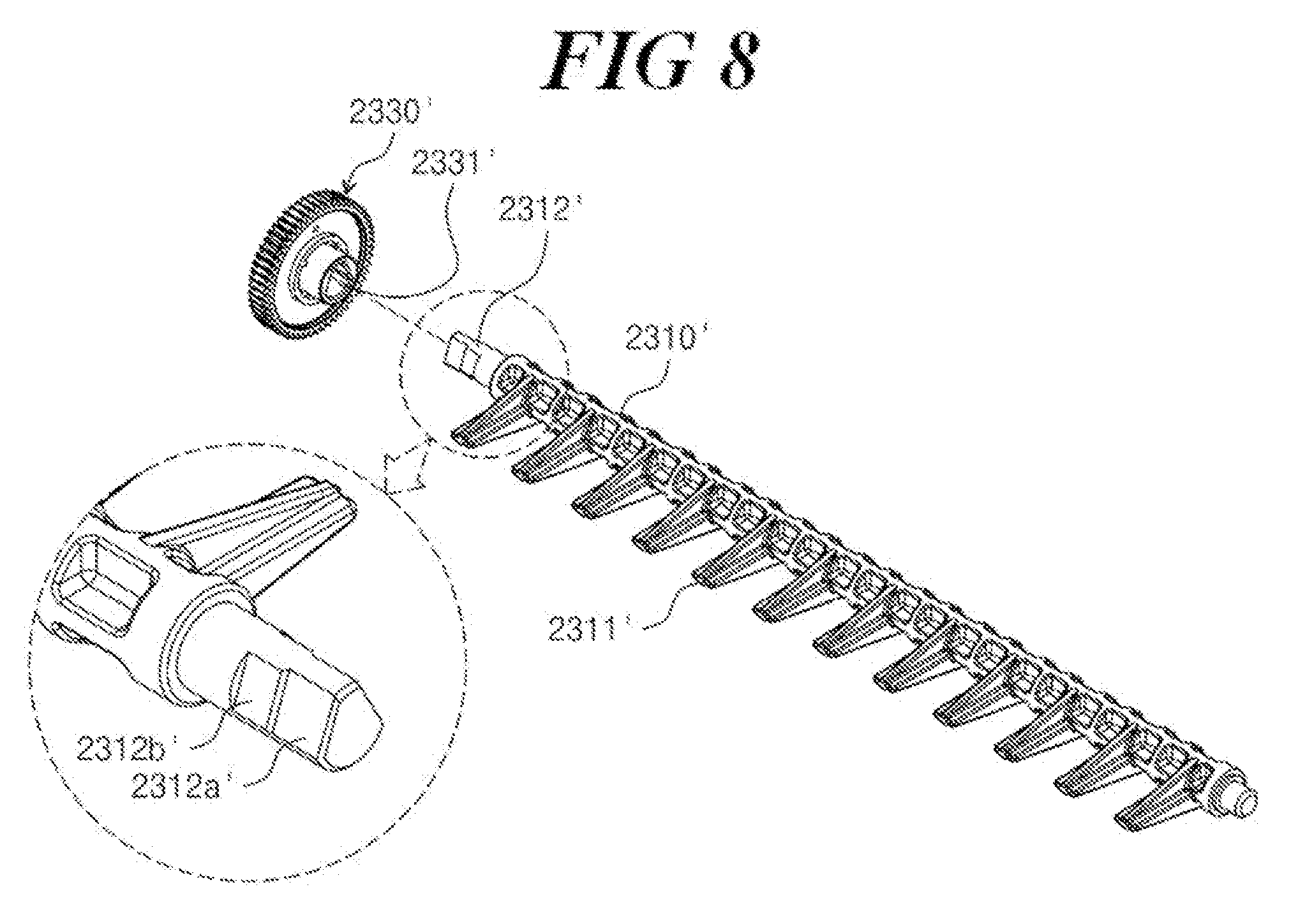
[0062] Hereinafter, an ice maker and a refrigerator having the same according to an alternative embodiment of the present invention will be described with reference to FIG. 8. However, since there is a difference in the shape of the ice removing shaft 2310' and the gear 2330' of the alternative embodiment, the following description focuses on the differences between the embodiments of FIGS. 7-8, and the descriptions and reference symbols of the embodiment of FIG. 7 will be cited for the like or identical portions.
[0063] FIG. 8 is an exploded perspective view showing a gear and an ice removing shaft according to an embodiment of the present invention.
[0064] Referring to FIG. 8, the ice removing shaft 2310' and the coupling hole 2331' in the gear 2330' may have a V or nearly a V shape (e.g., be formed through a V-cut process). Specifically, the coupling hole 2331' of the gear 2330' may have nearly a V shape (e.g., be a V-cut processed shape). Accordingly, the first portion 2312a' and the second portion 2312b' of the coupling unit 2312' of the ice removing shaft 2310' may also have V or nearly V shapes (e.g., be V-cut processed shapes). Accordingly, two planar surfaces may be in each of the first portion 2312a' and second portion 2312b' in the coupling unit 2312'.
[0065] In another embodiment, the coupling hole and the one end of the ice removing shaft in the coupling hole may have a circular cross-section in the plane perpendicular to the first direction X. Since the configuration in which the portion (e.g., of the coupling unit) inserted into the gear (e.g., into the coupling hole) has a first portion and a second portion having different cross-sectional areas, and the second portion is inserted into the coupling hole after the first portion is inserted into the coupling hole the same as or similar to the configurations shown in FIGS. 7 and 8, duplicative descriptions will be omitted.
[0066] According to embodiments of the present invention, an ice maker easy to assemble and a refrigerator having the same may be provided.
[0067] In addition, an ice maker with enhanced coupling force and a refrigerator having the same may be provided.
[0068] The above detailed description provides examples of the present invention. In addition, the above description explains by showing preferred embodiments of the present invention, and the present invention may be used in various different combinations, changes and environments. That is, the present invention may be modified or changed within the scope of the spirit of the present invention disclosed in this specification, within a scope equivalent to the disclosed contents, and/or within the scope of the technique(s) or knowledge of the prior art. The above embodiments describe the best conditions for implementing the technical spirit of the present invention, and various changes in the specific application fields and usages of the present invention also can be made. Accordingly, the detailed description of the present invention as described above shows disclosed embodiments and is not intended to limit the present invention. In addition, the appended claims should be interpreted as also including other embodiments.
* * * * *
D00000
D00001
D00002
D00003
D00004
D00005
D00006
D00007
XML
uspto.report is an independent third-party trademark research tool that is not affiliated, endorsed, or sponsored by the United States Patent and Trademark Office (USPTO) or any other governmental organization. The information provided by uspto.report is based on publicly available data at the time of writing and is intended for informational purposes only.
While we strive to provide accurate and up-to-date information, we do not guarantee the accuracy, completeness, reliability, or suitability of the information displayed on this site. The use of this site is at your own risk. Any reliance you place on such information is therefore strictly at your own risk.
All official trademark data, including owner information, should be verified by visiting the official USPTO website at www.uspto.gov. This site is not intended to replace professional legal advice and should not be used as a substitute for consulting with a legal professional who is knowledgeable about trademark law.