Linear-Acting Electric Pump Unit and Method for Operating Said Unit
Baum; Thomas ; et al.
U.S. patent application number 16/395679 was filed with the patent office on 2019-10-31 for linear-acting electric pump unit and method for operating said unit. The applicant listed for this patent is Thomas Magnete GmbH. Invention is credited to Thomas Baum, Edwin Kreuzberg, Diego Lehmann, Thomas Rolland, Fabian ROSNER.
| Application Number | 20190331107 16/395679 |
| Document ID | / |
| Family ID | 68105523 |
| Filed Date | 2019-10-31 |

| United States Patent Application | 20190331107 |
| Kind Code | A1 |
| Baum; Thomas ; et al. | October 31, 2019 |
Linear-Acting Electric Pump Unit and Method for Operating Said Unit
Abstract
A linear-acting electric pump unit and method for operating said unit. A linear-acting electric pump unit comprises an electromagnet and a pump unit. It is to be suitable for delivering gas/liquid mixtures. In order that it may be compactly assembled with other devices, it is to have a central inlet. The fluid delivered by the pump unit flows through the electromagnet and enters the pump unit on one side and leaves it on the other through the non-return valves, each arranged on the same centre line as the electromagnet. The pump unit can be used for delivery of gas/liquid mixtures, preferably in the sphere of combustion engines and their fuel supply systems and exhaust emission control systems.
| Inventors: | Baum; Thomas; (Hennef, DE) ; Rolland; Thomas; (Gebhardshain, DE) ; Lehmann; Diego; (Daaden, DE) ; ROSNER; Fabian; (Wenden, DE) ; Kreuzberg; Edwin; (Daaden, DE) | ||||||||||
| Applicant: |
|
||||||||||
|---|---|---|---|---|---|---|---|---|---|---|---|
| Family ID: | 68105523 | ||||||||||
| Appl. No.: | 16/395679 | ||||||||||
| Filed: | April 26, 2019 |
| Current U.S. Class: | 1/1 |
| Current CPC Class: | F04B 17/046 20130101; F04B 2203/0405 20130101; F04B 45/027 20130101; F04B 49/02 20130101; F04B 49/06 20130101; F04B 43/04 20130101; F04B 35/045 20130101; F04B 49/065 20130101 |
| International Class: | F04B 49/02 20060101 F04B049/02; F04B 17/04 20060101 F04B017/04; F04B 43/04 20060101 F04B043/04; F04B 49/06 20060101 F04B049/06 |
Foreign Application Data
| Date | Code | Application Number |
|---|---|---|
| Apr 28, 2018 | DE | 10 2018 003 507.8 |
Claims
1. A linear-acting electric pump unit, comprising: at least one electromagnet; and a pump unit driven by the electromagnet; wherein the pump unit comprising at least two non-return valves; wherein the fluid delivered by the pump unit flows through the electromagnet and enters the pump unit on one side and leaves it on the other through the non-return valves, each arranged on a same centre line as the electromagnet.
2. The linear-acting electric pump unit according to claim 1, wherein the electromagnet comprises at least a solenoid coil, a magnetic pole, a back iron, a magnet yoke and an armature, the armature being moveably supported on a tube, which also carries the fluid delivered by the pump unit.
3. The linear-acting electric pump unit according to claim 1, wherein the pump unit comprises a highly elastic bellows, which by a first moveable cover is deformed by an armature as the armature moves in opposition to the force of a return spring.
4. The linear-acting electric pump unit according to claim 1, wherein the pump unit comprises a cylinder and a moveable piston forming a seal therein, which is displaced by an armature as the armature moves in opposition to the force of a return spring.
5. The linear-acting electric pump unit according to claim 2, wherein when the solenoid coil is energized the armature runs into the magnetic pole and in so doing causes the pump unit to expel fluid from the second non-return valve, a return spring pushing the armature out of the magnetic pole once the solenoid coil is switched off and in so doing causing the pump unit to draw in fluid through the first non-return valve.
6. The linear-acting electric pump unit according to claim 2, wherein when the solenoid coil is energized the armature runs into the magnetic pole and in so doing causes the pump unit to draw in fluid through the first non-return valve, a return spring pushing the armature out of the magnetic pole once the solenoid coil is switched off and in so doing causing the pump unit to expel fluid from the second non-return valve.
7. The linear-acting electric pump unit according to claim 1, wherein the pump unit comprises a first non-return valve, which comprises a valve seat and a valve body, the valve body comprising a highly elastic disk and a centrally arranged holder.
8. The linear-acting electric pump unit according to claim 7, wherein the pump unit comprises a second non-return valve, which comprises a valve seat and a valve body, the valve body comprising a highly elastic disk and a centrally arranged holder.
9. The linear-acting electric pump unit according to claim 1, wherein an armature, at the end of its stroke with a solenoid coil in an energized state, is brought to a standstill by force of a return spring and reactive forces of the electric pump unit and that the armature, at the end of its stroke with the solenoid coil in an unenergized state, is likewise brought to a standstill by forces of the return spring and the electric pump unit.
10. A method for operating a linear-acting electric pump unit according to claim 1 wherein before commencing operation of the pump, an electrical control supplying the electric pump unit with electrical energy determines a coil temperature through a simultaneous measurement of an electrical current and an electrical voltage of a solenoid coil and in the event of a measured coil temperature below a predefined limit a solenoid coil is first activated by a high-frequency pulse signal, which does not produce any movement of an armature, but heats the solenoid coil, the measurement of an electrical resistance of the solenoid coil being regularly repeated and the actual pump operation being commenced at a lower frequency once the coil temperature exceeds the said predefined limit.
11. The method for operating a linear-acting electric pump unit according to claim 10 wherein the electric pump unit is supplied with electrical energy by an electrical control and is equipped with a pressure sensor, which has a fluid connection to an outlet of the electric pump unit and an electrical connection to the control the control monitoring the time profiles of the electrical current through the solenoid coil and the pressure on the outlet whilst the pump is in operation and comparing them with stored set values, and any malfunctioning of the solenoid coil, the electric pump unit or the pressure sensor being inferred from the comparison of the time profiles of the electrical current through the solenoid coil and the pressure on the outlet, and, where necessary, a fault message being sent to an overriding electrical control system.
Description
CROSS-REFERENCE TO RELATED APPLICATIONS
[0001] This application claims the benefit and priority of German Application No. 10 2018 003 507.8 filed on Apr. 28, 2018. The entire disclosure of the above application is incorporated herein by reference.
FIELD
[0002] The present disclosure relates to an electric pump unit and to a method for operating the electric pump unit through interaction with an electrical control.
BACKGROUND
[0003] This section provides background information related to the present disclosure which is not necessarily prior art.
[0004] Electric pump units comprising an electric motor and a pump are known and in widespread use.
[0005] Linear-acting electric pump units, the electric actuator of which is an electromagnet, are also known, for example from the published specification DE 101 32 959 A1.
[0006] These electric pump units are designed for operation with liquids and are not ideal for operation with liquid/gas mixtures. Nor are they generally well-suited, without additional lines, to assembly with other devices such as electrovalves, for example.
[0007] Rotary pumps are generally not designed to maintain a gas pressure when at rest.
[0008] The published specification DE 10 2016 002 348 A1 shows a bellows pump having electrovalves, which is suitable for operation with fluid mixtures, but the teaching does not extend to cost-effective construction of the electric pump unit.
SUMMARY
[0009] This section provides a general summary of the disclosure, and is not a comprehensive disclosure of its full scope or all of its features.
[0010] The electric pump unit is to comprise an electromagnet as drive and be suitable for delivering gas/liquid mixtures. In order that it may be compactly assembled with other devices, it is to have a central inlet. Finally, the electromagnet driving it should be energy-efficient in operation.
[0011] A linear-acting electric pump unit comprises at least one electromagnet and a pump unit, which is driven by the electromagnet and comprises at least two non-return valves, the fluid delivered by the electric pump unit flowing through the electromagnet and entering the pump unit on one side and leaving it on the other through the non-return valves, each arranged on the same centre line as the electromagnet.
[0012] The electromagnet preferably comprises at least a solenoid coil, a magnetic pole, a back iron, a magnet yoke and an armature, the armature being moveably supported on a tube, which also carries the fluid delivered by the electric pump unit.
[0013] In a first embodiment the pump unit comprises a highly elastic bellows, which by means of a first moveable cover is deformed by the armature as the armature moves in opposition to the force of a return spring.
[0014] In a second embodiment the pump unit comprises a cylinder and a moveable piston forming a seal therein, which is displaced by the armature as the armature moves in opposition to the force of a return spring.
[0015] When the solenoid coil is energized the armature runs into the magnetic pole and in so doing causes the pump unit to expel fluid from the second non-return valve, the return spring pushing the armature out of the magnetic pole once the solenoid coil is switched off and in so doing causing the pump unit to draw in fluid through the first non-return valve.
[0016] In an alternative to the arrangement described above, the armature runs into the magnetic pole when the solenoid coil is energized and in so doing causes the pump unit to draw in fluid through the first non-return valve, the return spring pushing the armature out of the magnetic pole once the solenoid coil is switched off and in so doing causing the pump unit to expel fluid from the second non-return valve.
[0017] The pump unit advantageously comprises a first non-return valve, which comprises a valve seat and a valve body, the valve body comprising a highly elastic disk and a centrally arranged holder.
[0018] The pump unit likewise advantageously comprises a second non-return valve, which comprises a valve seat and a valve body, the valve body comprising a highly elastic disk and a centrally arranged holder.
[0019] The armature, at the end of its stroke with the solenoid coil in the energized state, is advantageously brought to a standstill not by a limit stop but by the force of the return spring and the reactive forces of the pump unit, and at the end of its stroke with the solenoid coil in the unenergized state the armature is likewise brought to a standstill not by a limit stop, but by forces of the return spring and the pump unit.
[0020] For operating the linear-acting electric pump unit, the electric pump unit is supplied with electrical energy by an electrical control. Here, before commencing operation of the pump, the coil temperature is determined through a simultaneous measurement of the electrical current and the electrical voltage of the solenoid coil and in the event of a measured coil temperature below a predefined limit the solenoid coil is first activated by a high-frequency pulse signal. The high-frequency pulse signal does not produce any significant movement of the armature, but heats the solenoid coil. Here the measurement of the electrical resistance of the solenoid coil is regularly repeated, and the actual pump operation is commenced at a lower frequency once the coil temperature exceeds the said predefined limit.
[0021] The predefined coil temperature limit depends on the fluid being pumped, in particular its water content.
[0022] The frequency of the high-frequency pulse signal lies considerably (more than 30%, preferably more than 60%) above the natural frequency of the spring-mass system of the arrangement comprising the armature and the return spring.
[0023] The method for operating the linear-acting electric pump unit can be improved, by equipping the electric pump unit, supplied with electrical energy by an electrical control, with a pressure sensor which has a fluid connection to an outlet of the electric pump unit and an electrical connection to the control. Here, the electrical control monitors the time profiles of the electrical current through the solenoid coil and the pressure on the outlet whilst the pump is in operation, and compares them with stored set values.
[0024] From the comparison of the time profiles of the electrical current through the solenoid coil and the pressure on the outlet the electrical control infers any malfunctioning of the solenoid coil, the electric pump unit or the pressure sensor. If necessary, a fault message is sent to an overriding electrical control system.
[0025] Electric pump units are used for delivering gas/liquid mixtures, preferably in the sphere of combustion engines and their fuel supply systems and exhaust emission control systems.
[0026] Further areas of applicability will become apparent from the description provided herein. The description and specific examples in this summary are intended for purposes of illustration only and are not intended to limit the scope of the present disclosure.
DRAWINGS
[0027] The drawings described herein are for illustrative purposes only of selected embodiments and not all possible implementations, and are not intended to limit the scope of the present disclosure.
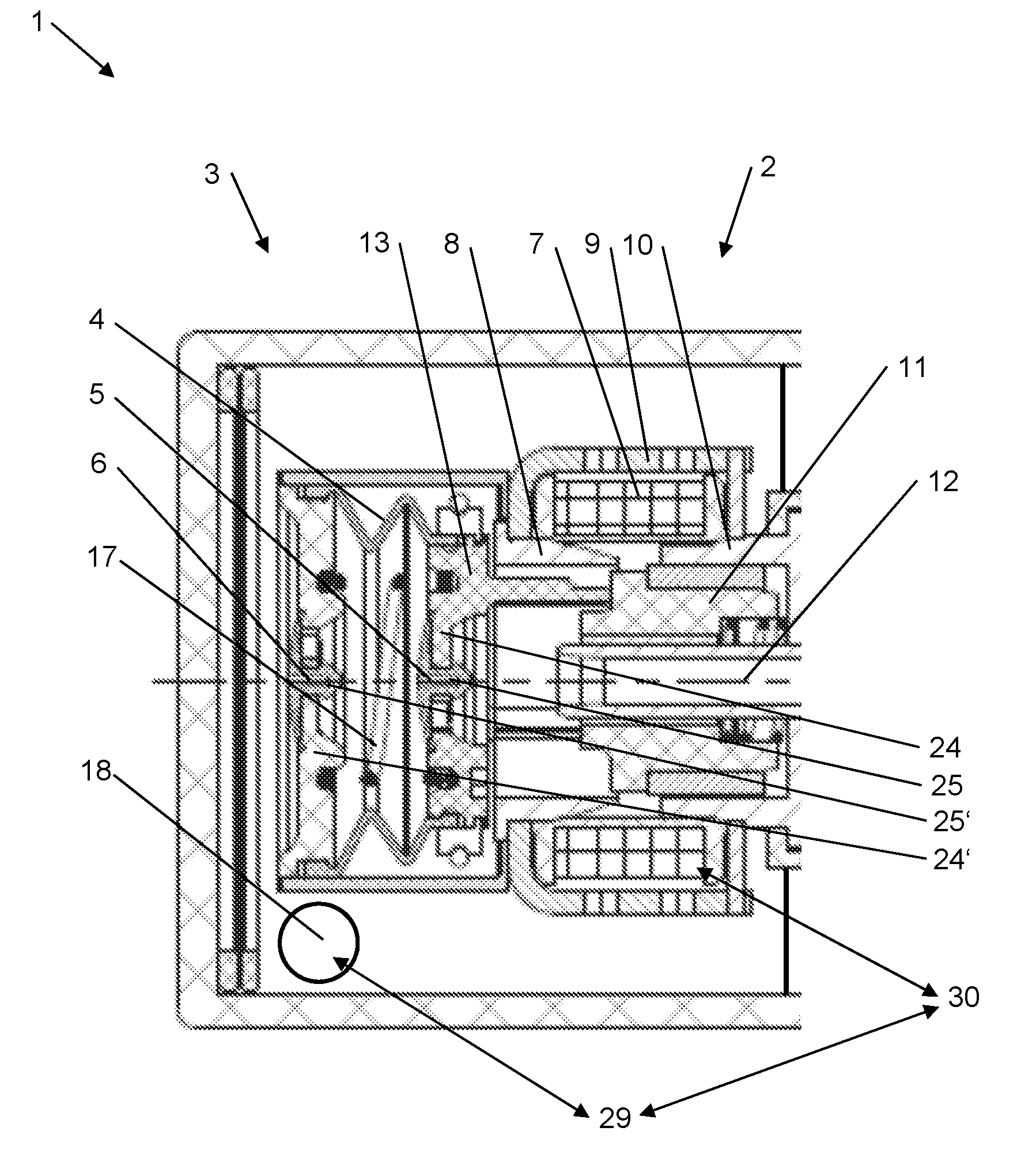
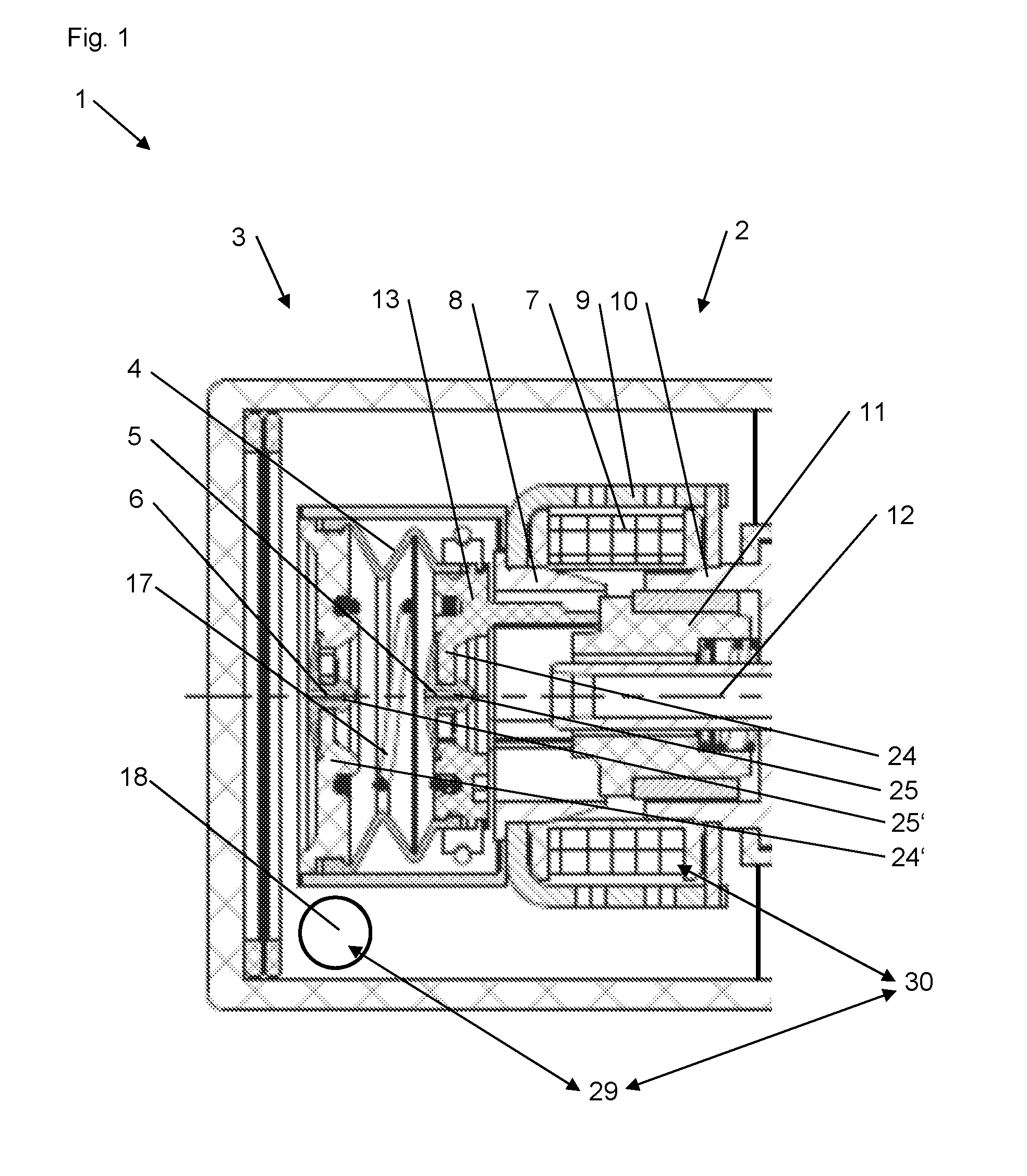
[0028] FIG. 1 shows the electric pump unit in section as an integral part of a larger device with unenergized electromagnet.
[0029] FIG. 2 shows the electric pump unit with energized electromagnet.
[0030] Corresponding reference numerals indicate corresponding parts throughout the several views of the drawings.
DETAILED DESCRIPTION
[0031] Example embodiments will now be described more fully with reference to the accompanying drawings.
[0032] The linear-acting electric pump unit (1) according to FIG. 1 and FIG. 2 comprises an electromagnet (2) and a pump unit (3) driven by the electromagnet (2). Here the pump unit (3) comprises two non-return valves (5, 6), the fluid delivered by the pump unit (3) flowing through the electromagnet (2) and entering the pump unit (3) on one side and leaving it on the other through the non-return valves (5, 6), each arranged on the same centre line as the electromagnet (2).
[0033] The electromagnet (2) comprises a solenoid coil (7), a magnetic pole (8), a back iron (9), a magnet yoke (10) and an armature (11), the armature (11) being moveably supported on a tube (12), which also carries the fluid delivered by the electric pump unit (3).
[0034] In the embodiment according to FIG. 1 and FIG. 2 the pump unit (3) comprises a highly elastic bellows (4), which by a first moveable cover (13) is deformed by the armature (11) as the armature (11) moves in opposition to the force of a return spring (17).
[0035] In another embodiment, the pump unit (3) comprises a cylinder (15) and a moveable piston (16) forming a seal therein, which is displaced by the armature (11) as the armature (11) moves in opposition to the force of a return spring (17).
[0036] As represented in FIG. 2, when the solenoid coil (7) is energized the armature (11) runs into the magnetic pole (8) and in so doing causes the pump unit (3) to expel fluid from the second non-return valve (6), the return spring (17) pushing the armature (11) out of the magnetic pole (8) once the solenoid coil (7) is switched off and in so doing causing the pump unit (3) to draw in fluid through the first non-return valve (5).
[0037] In another embodiment, the armature (11) likewise runs into the magnetic pole (8) when the solenoid coil (7) is energized, but in so doing causes the pump unit (3) to draw in fluid through the first non-return valve (5), the return spring (17) pushing the armature (11) out of the magnetic pole (8) once the solenoid coil (7) is switched off and in so doing causing the pump unit (3) to expel fluid from the second non-return valve (6).
[0038] The pump unit (3) comprises a first non-return valve (5), which comprises a valve seat (24) and a valve body (25), the valve body (25) comprising a highly elastic disk (26) and a centrally arranged holder (27).
[0039] The pump unit (3) comprises a second non-return valve (6), which likewise comprises a valve seat (24') and a valve body (25'), the valve body (25') comprising a highly elastic disk (26') and a centrally arranged holder (27').
[0040] The armature (11), at the end of its stroke with the solenoid coil (7) in the energized state, is brought to a standstill by the force of the return spring (17) and the reactive forces of the electric pump unit (3). At the end of its stroke with the solenoid coil (7) in the unenergized state, the armature (11) is likewise brought to a standstill by forces of the return spring (17) and the electric pump unit (3).
LIST OF REFERENCE NUMERALS
[0041] 1. electric pump unit [0042] 2. electromagnet [0043] 3. pump unit [0044] 4. bellows [0045] 5. non-return valve [0046] 6. non-return valve [0047] 7. solenoid coil [0048] 8. magnetic pole [0049] 9. back iron [0050] 10. magnet yoke [0051] 11. armature [0052] 12. tube [0053] 13. cover [0054] 14. cover [0055] 15. cylinder [0056] 16. piston [0057] 17. return spring [0058] 18. outlet [0059] 24. valve seat [0060] 25. valve body [0061] 26. disk [0062] 27. holder [0063] 29. pressure sensor [0064] 30. electrical control
[0065] The foregoing description of the embodiments has been provided for purposes of illustration and description. It is not intended to be exhaustive or to limit the disclosure. Individual elements or features of a particular embodiment are generally not limited to that particular embodiment, but, where applicable, are interchangeable and can be used in a selected embodiment, even if not specifically shown or described. The same may also be varied in many ways. Such variations are not to be regarded as a departure from the disclosure, and all such modifications are intended to be included within the scope of the disclosure.
* * * * *
D00000
D00001
D00002
XML
uspto.report is an independent third-party trademark research tool that is not affiliated, endorsed, or sponsored by the United States Patent and Trademark Office (USPTO) or any other governmental organization. The information provided by uspto.report is based on publicly available data at the time of writing and is intended for informational purposes only.
While we strive to provide accurate and up-to-date information, we do not guarantee the accuracy, completeness, reliability, or suitability of the information displayed on this site. The use of this site is at your own risk. Any reliance you place on such information is therefore strictly at your own risk.
All official trademark data, including owner information, should be verified by visiting the official USPTO website at www.uspto.gov. This site is not intended to replace professional legal advice and should not be used as a substitute for consulting with a legal professional who is knowledgeable about trademark law.