Swash Plate Compressor
MITSUOKA; Tetsuya ; et al.
U.S. patent application number 16/461501 was filed with the patent office on 2019-10-31 for swash plate compressor. This patent application is currently assigned to KABUSHIKI KAISHA TOYOTA JIDOSHOKKI. The applicant listed for this patent is KABUSHIKI KAISHA TOYOTA JIDOSHOKKI. Invention is credited to Hidetaka HAYASHI, Tetsuya MITSUOKA, Shino OKUBO.
| Application Number | 20190331105 16/461501 |
| Document ID | / |
| Family ID | 62145389 |
| Filed Date | 2019-10-31 |


| United States Patent Application | 20190331105 |
| Kind Code | A1 |
| MITSUOKA; Tetsuya ; et al. | October 31, 2019 |
SWASH PLATE COMPRESSOR
Abstract
A swash plate compressor according to the present invention includes a first slide layer formed between a swash plate and shoes; and a second slide layer formed between cylinder bores and pistons. The first slide layer and the second slide layer each contain binder resin and solid lubricant. The first slide layer has a smaller contact angle of lubricating oil than the second slide layer.
| Inventors: | MITSUOKA; Tetsuya; (Aichi-ken, JP) ; HAYASHI; Hidetaka; (Aichi-ken, JP) ; OKUBO; Shino; (Aichi-ken, JP) | ||||||||||
| Applicant: |
|
||||||||||
|---|---|---|---|---|---|---|---|---|---|---|---|
| Assignee: | KABUSHIKI KAISHA TOYOTA
JIDOSHOKKI Aichi-ken JP |
||||||||||
| Family ID: | 62145389 | ||||||||||
| Appl. No.: | 16/461501 | ||||||||||
| Filed: | October 20, 2017 | ||||||||||
| PCT Filed: | October 20, 2017 | ||||||||||
| PCT NO: | PCT/JP2017/037935 | ||||||||||
| 371 Date: | May 16, 2019 |
| Current U.S. Class: | 1/1 |
| Current CPC Class: | F04B 49/12 20130101; F04B 27/0886 20130101; F04B 27/12 20130101; F04B 27/0882 20130101; F04B 39/00 20130101; F04B 27/10 20130101; F04B 27/1072 20130101; F04B 27/109 20130101; F04B 27/18 20130101; F04B 39/0292 20130101; F04B 39/02 20130101 |
| International Class: | F04B 39/02 20060101 F04B039/02; F04B 27/12 20060101 F04B027/12; F04B 27/18 20060101 F04B027/18; F04B 49/12 20060101 F04B049/12 |
Foreign Application Data
| Date | Code | Application Number |
|---|---|---|
| Nov 17, 2016 | JP | 2016-223937 |
Claims
1.-4. (canceled)
5. A swash plate compressor comprising: a housing that includes a swash-plate chamber and a plurality of cylinder bores; a drive shaft that is supported by the housing and is rotatable within the swash-plate chamber; a swash plate that is disposed within the swash-plate chamber and is synchronously rotatable with the drive shaft; shoes that slide on the swash plate; a piston that is allowed by the shoes to make strokes that depend on an inclination angle of the swash plate to reciprocate within the corresponding cylinder bore to compress refrigerant that contains lubricating oil; a first slide layer formed between the swash plate and the shoes; and a second slide layer formed between the cylinder bores and the piston, wherein the first slide layer and the second slide layer each contain binder resin and solid lubricant, the solid lubricant of the first slide layer contains ultra high molecular weight polyethylene, and the solid lubricant of the second slide layer contains fluorine resin, and the first slide layer has a smaller contact angle of the lubricating oil than the second slide layer.
6. The swash plate compressor according to claim 5, wherein the swash-plate chamber directly communicates with an evaporator.
7. The swash plate compressor according to claim 6, further comprising: a linkage that is disposed within the swash-plate chamber and allows a change in the inclination angle of the swash plate; and an actuator that is disposed within the swash-plate chamber and changes the inclination angle of the swash plate, wherein the actuator includes: a partition body that is rotatable with the drive shaft within the swash-plate chamber; a movable body that is rotatable with the drive shaft within the swash-plate chamber and moves with respect to the partition body in an axis direction of the drive shaft to change the inclination angle; a control pressure chamber that is defined by the partition body and the movable body and has a pressure within the control pressure chamber that moves the movable body; and a control mechanism that controls the pressure within the control pressure chamber.
Description
TECHNICAL FIELD
[0001] The present invention relates to a swash plate compressor.
BACKGROUND ART
[0002] A general swash plate compressor includes a housing, a drive shaft, a swash plate, a plurality pairs of shoes, and a plurality of pistons. The housing includes a swash-plate chamber and a plurality of cylinder bores. The drive shaft is supported by the housing and is rotatable within the swash-plate chamber. The swash plate is disposed within the swash-plate chamber and is synchronously rotatable with the drive shaft. Each pair of shoes slides on the swash plate. The pairs of shoes allow the respective pistons to make strokes that depend on an inclination angle of the swash plate to reciprocate within the respective cylinder bores. First slide layers are formed on both surfaces of the swash plate on which the shoes slide. Second slide layers are formed on outer peripheral surfaces of the pistons that slide on the respective cylinder bores.
[0003] Patent Document 1 discloses resin materials that may be used for the first and second slide layers. The resin materials contain fluorine resins such as polytetrafluoroethylene (PTFE), and ultra high molecular weight polyethylene, for example. It is thought that, in the swash plate compressor, the first slide layer allows the shoes to appropriately slide on the swash plate, and the second slide layer allows the pistons to appropriately slide in the cylinder bores.
CITATION LIST
Patent Document
[0004] Patent Document 1: Japanese Patent Application Publication No. 2010-60262
SUMMARY OF INVENTION
Technical Problem
[0005] However, if a swash plate compressor, an evaporator, a condenser, and the like constitute a vehicle refrigeration circuit, and the refrigeration circuit is filled with refrigerant and lubricating oil and operates; much lubricating oil exists in some portions of a swash-plate chamber and little lubricating oil exists in other portions of the swash-plate chamber, according to knowledge of the present inventors. Lubricating oil is less likely to exist especially between a swash plate and shoes, and is likely to exist especially between cylinder bores and pistons. On the other hand, much lubricating oil is desirable between the swash plate and the shoes, according to knowledge of the present inventors.
[0006] In this regard, if a first slide layer is made of the conventional resin materials described above, some selections of the resin materials may cause wear or seizure between a swash plate and shoes and thus deteriorate durability.
[0007] The present invention has been made in view of the conventional circumstances described above. An object of the present invention is to provide a swash plate compressor that has excellent durability.
Solution to Problem
[0008] A swash plate compressor according to the present invention includes: a housing that includes a swash-plate chamber and a plurality of cylinder bores; a drive shaft that is supported by the housing and is rotatable within the swash-plate chamber; a swash plate that is disposed within the swash-plate chamber and is synchronously rotatable with the drive shaft; shoes that slide on the swash plate; a piston that is allowed by the shoes to make strokes that depend on an inclination angle of the swash plate to reciprocate within the corresponding cylinder bore to compress refrigerant that contains lubricating oil;
[0009] a first slide layer formed between the swash plate and the shoes; and a second slide layer formed between the cylinder bores and the piston, and
[0010] the first slide layer and the second slide layer each contain binder resin and solid lubricant, and
[0011] the first slide layer has a smaller contact angle of the lubricating oil than the second slide layer.
[0012] As shown in results of an experiment by the present inventors, the first slide layer that contains the binder resin and the solid lubricant allows the shoes to appropriately slide on the swash plate in the swash plate compressor according to the present invention. Further, the second slide layer that contains the binder resin and the solid lubricant allows the piston to appropriately slide in the cylinder bores.
[0013] Especially in the swash plate compressor, the first slide layer has a smaller contact angle of the lubricating oil than the second slide layer. Therefore, the first slide layer has higher oil wettability than the second slide layer. Therefore, much lubricating oil is allowed to exist even between the swash plate and the shoes where lubricating oil is less likely to exist due to the structure of the swash plate compressor but much lubricating oil is desirable. Therefore; wear or seizure is less likely to occur between the swash plate and the shoes.
[0014] Further, much lubricating oil is not allowed to exist between the cylinder bores and the pistons where lubricating oil is likely to exist due to the structure of the swash plate compressor but much lubricating oil is not desirable. That is, lubricating oil is allowed to move to the swash-plate chamber through between the cylinder bores and the pistons so that the lubricating oil exists between the swash plate and the shoes.
[0015] Therefore; the swash plate compressor according to the present invention has excellent durability.
[0016] The first and second slide layers each contain the binder resin and the solid lubricant. The binder resin has a holding property that holds the solid lubricant to decrease separation of the solid lubricant, durability against shear force that repeatedly acts under layers of films (hardness as a base), wear resistance against breakage, and heat resistance, for example. For example, polyimide-imide (PAI), polyimide, epoxy resin, or phenolic resin may be used as the binder resin. Taking cost and properties into consideration, PAI is optimum for the binder resin.
[0017] The solid lubricant is held by the binder resin, and has a low shear force and a low coefficient of friction at an outermost surface. For example, fluorine resin, molybdenum dioxide, graphite, and ultra-high-molecular-weight-polyethylene particles may be used as the solid lubricant. Fluorine resin and ultra-high-molecular-weight-polyethylene particles each improve a slippery property by forming a film on slide surfaces of the first and second slide layers and being transferred to an opposite material. Molybdenum dioxide and graphite each improve a slippery property by a crystal structure that has a low shear force, and provide less wear under high loads. According to results of an experiment by the present inventors, fluorine resin has a sliding property, such as wear resistance and seizure resistance, but has oil repellency and a relatively large contact angle of lubricating oil. On the other hand, ultra-high-molecular-weight-polyethylene particles have a poorer sliding property than fluorine resin, but have lipophilicity and a relatively small contact angle of lubricating oil. Alternatively, melamine cyanurate (MCA), calcium fluoride, and soft metal, such as copper and tin, may be used as the solid lubricant.
[0018] In addition to the binder resin and the solid lubricant, the first and second slide layers may each contain additives. As the additives, an additive may be used that improves hardness of the first and second slide layers, such as hard particles of, for example, titanium dioxide, tricalcium phosphate, alumina, silica, silicon carbide, and silicon nitride.
[0019] The first and second slide layers may each also contain a surfactant, a coupling agent, a processing stabilizer, and an antioxidant, for example.
[0020] It is preferable that the solid lubricant of the first slide layer contains ultra high molecular weight polyethylene, and the solid lubricant of the second slide layer contains fluorine resin. Since fluorine resin has oil repellency and ultra high molecular weight polyethylene has lipophilicity, as described above, the solid lubricant of the first slide layer that contains ultra high molecular weight polyethylene and the solid lubricant of the second slide layer that contains fluorine resin surely implement the present invention.
[0021] A swash plate compressor according to the present invention has a significant operational advantage if the swash-plate chamber directly communicates with an evaporator. That is, in a swash plate compressor in which a swash-plate chamber directly communicates with an evaporator, liquid refrigerant that has returned into the swash-plate chamber from the evaporator is likely to wash away lubricating oil on shoes and a swash plate. Consequently, a first slide layer between the swash plate and the shoes is likely to be worn and cause seizure. On the contrary, a first slide layer has high oil wettability in a swash plate compressor according to the present invention, and thus refrigerant is less likely to wash away lubricating oil on the first slide layer even if the swash-plate chamber directly communicates with an evaporator. Even if lubricating oil is washed away, lubricating oil between the cylinder bores and the pistons moves to the swash-plate chamber and into between the swash plate and the shoes. Consequently, lubricating oil is likely to be supplied to between the swash plate and the shoes.
[0022] A swash plate compressor according to the present invention has a significant operational advantage if the swash plate compressor further includes: a linkage that is disposed within the swash-plate chamber and allows a change in the inclination angle of the swash plate; and an actuator that is disposed within the swash-plate chamber and changes the inclination angle of the swash plate. It is preferable that the actuator includes a partition body that is rotatable with the drive shaft within the swash-plate chamber, a movable body that is rotatable with the drive shaft within the swash-plate chamber and moves with respect to the partition body in an axis direction of the drive shaft to change the inclination angle, a control pressure chamber that is defined by the partition body and the movable body and has a pressure within the control pressure chamber that moves the movable body, and a control mechanism that controls the pressure within the control pressure chamber.
[0023] That is, such a swash plate compressor that includes a linkage and an actuator has a swash-plate chamber, a volume of which is smaller than that of a swash-plate chamber of a swash plate compressor that changes an inclination angle of a swash plate by controlling pressure within a crank chamber. Therefore, such a swash plate compressor has a difficulty in supplying lubricating oil to a first slide layer between a swash plate and shoes. Consequently, the first slide layer between the swash plate and the shoes is likely to be worn and cause seizure. On the contrary, a swash plate compressor according to the present invention has high oil wettability of a first slide layer. Consequently, refrigerant is less likely to wash away lubricating oil on the first slide layer even if a swash-plate chamber includes a linkage and an actuator and thus has a small volume.
Advantageous Effects of Invention
[0024] A swash plate compressor according to the present invention has excellent durability.
BRIEF DESCRIPTION OF DRAWINGS
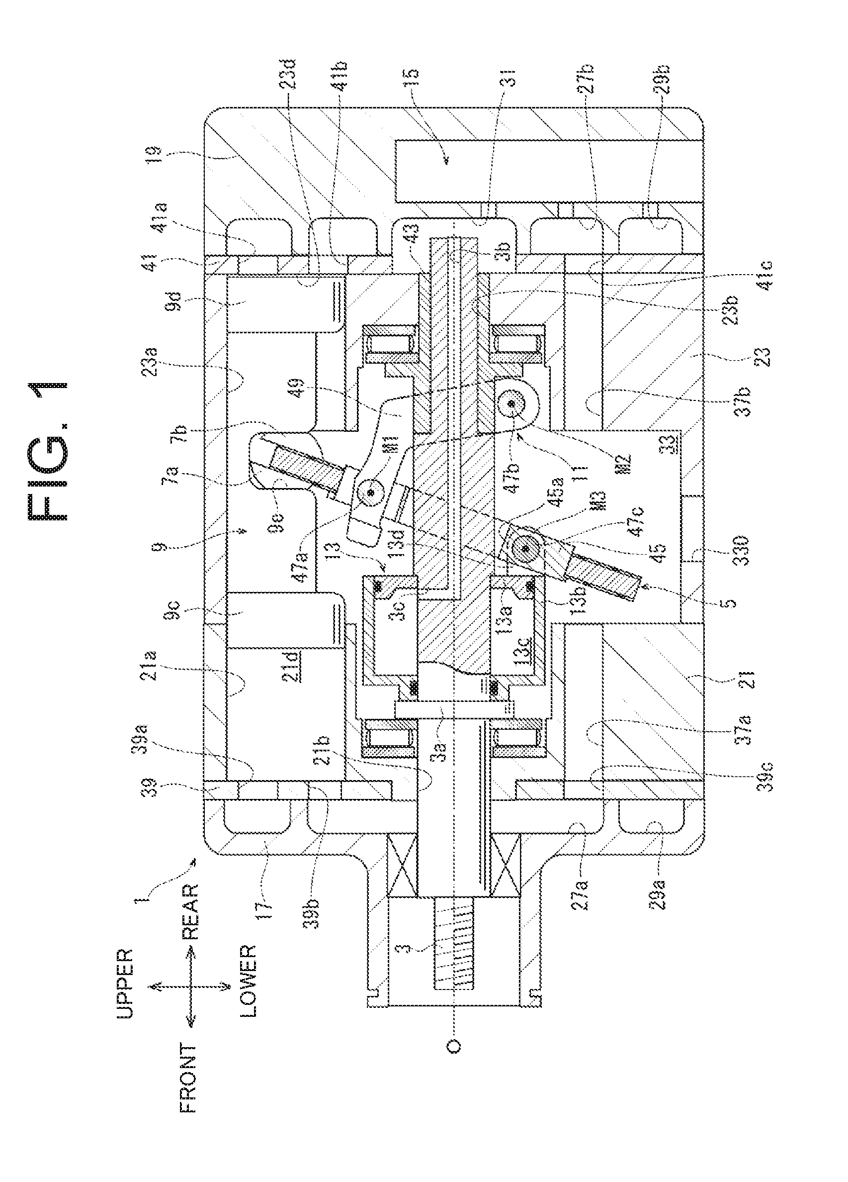
[0025] FIG. 1 is a cross-sectional view illustrating a swash plate compressor according to a first embodiment.
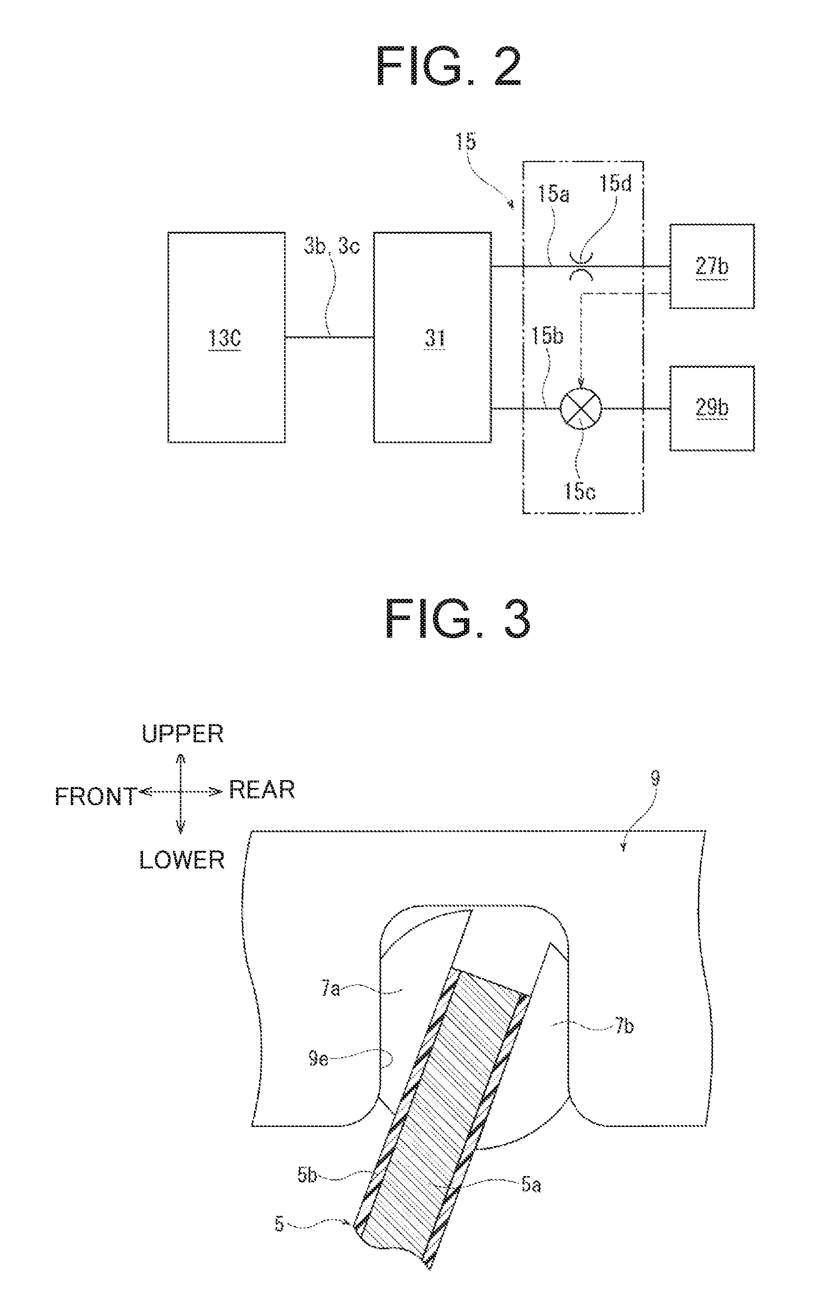
[0026] FIG. 2 is a schematic diagram illustrating a control mechanism related to the swash plate compressor according to the first embodiment.
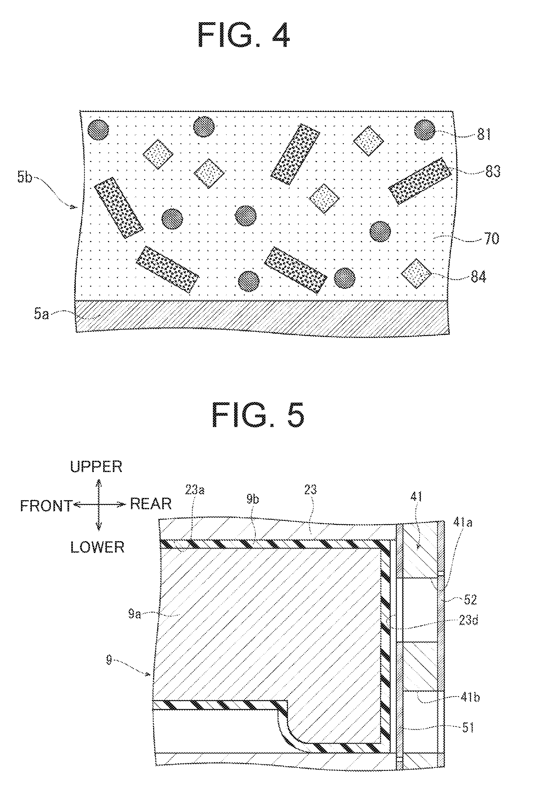
[0027] FIG. 3 is an enlarged cross-sectional view illustrating a swash plate, shoes, and a piston of the swash plate compressor according to the first embodiment.
[0028] FIG. 4 is a schematic cross-sectional view illustrating a swash-plate main body and a first slide layer of the swash plate compressor according to the first embodiment.
[0029] FIG. 5 is an enlarged cross-sectional view illustrating a cylinder bore and a piston of the swash plate compressor according to the first embodiment.
[0030] FIG. 6 is a schematic cross-sectional view illustrating a piston main body and a second slide layer of the swash plate compressor according to the first embodiment.
DESCRIPTION OF EMBODIMENT
[0031] Hereinafter, a first embodiment of the present invention will be described referring to the drawings. In FIG. 1, a left side of a compressor is defined as a front side, a right side of the compressor is defined as a rear side, an upper side of the compressor is defined as an upper side, and a lower side of the compressor is defined as a lower side. Each direction in FIGS. 3 and 5 matches the corresponding direction in FIG. 1.
[0032] A swash plate compressor (hereinafter referred to as a compressor) according to the first embodiment includes a housing 1, a drive shaft 3, a swash plate 5, a plurality of pairs of shoes 7a and 7b, a plurality of pistons 9, a linkage 11, and an actuator 13, as illustrated in FIG. 1, and also includes a control mechanism 15 illustrated in FIG. 2.
[0033] As illustrated in FIG. 1, the housing 1 includes a front housing 17, a rear housing 19, a first cylinder block 21, and a second cylinder block 23.
[0034] The front housing 17 is on the front side of the compressor. The rear housing 19 is on the rear side of the compressor. The first cylinder block 21 and the second cylinder block 23 are between the front housing 17 and the rear housing 19.
[0035] The front housing 17 includes a first suction chamber 27a and a first discharge chamber 29a. The first suction chamber 27a is on an inner side of the front housing 17. The first discharge chamber 29a is on an outer side of the front housing 17.
[0036] The rear housing 19 includes the control mechanism 15. The rear housing 19 includes a second suction chamber 27b, a second discharge chamber 29b, and a pressure adjusting chamber 31. The second suction chamber 27b is on an inner side of the rear housing 19. The second discharge chamber 29b is on an outer side of the rear housing 19. The pressure adjusting chamber 31 is at a central portion of the rear housing 19. A discharge passage (not illustrated) connects the first discharge chamber 29a with the second discharge chamber 29b. The discharge passage includes an outlet (not illustrated).
[0037] A swash-plate chamber 33 is formed within the first cylinder block 21 and the second cylinder block 23. The swash-plate chamber 33 is substantially at the center of the housing 1. The swash-plate chamber 33 directly communicates with an evaporator (not illustrated) through an inlet 330 of the second cylinder block 23.
[0038] The first cylinder block 21 includes a plurality of first cylinder bores 21a that are concentrically arranged at equal angular intervals, and are parallel with each other. The first cylinder block 21 also includes a first shaft hole 21b through which the drive shaft 3 is inserted. The first cylinder block 21 also includes a first suction passage 37a that connects the swash-plate chamber 33 with the first suction chamber 27a.
[0039] A first valve unit 39 is disposed between the front housing 17 and the first cylinder block 21. The first valve unit 39 includes suction ports 39b and discharge ports 39a. The number of the suction ports 39b is the same as that of the first cylinder bores 21a. The number of the discharge ports 39a is the same as that of the first cylinder bores 21a. The suction ports 39b connect the respective first cylinder bores 21a with the first suction chamber 27a through a suction valve (not illustrated). The discharge ports 39a connect the respective first cylinder bores 21a with the first discharge chamber 29a through a discharge valve (not illustrated). The first valve unit 39 also includes a communication hole 39c. The first suction chamber 27a communicates with the swash-plate chamber 33 through the communication hole 39c and the first suction passage 37a.
[0040] The second cylinder block 23 includes a plurality of second cylinder bores 23a, similarly as the first cylinder block 21. The second cylinder block 23 also includes a second shaft hole 23b through which the drive shaft 3 is inserted. The second shaft hole 23b communicates with the pressure adjusting chamber 31. The second cylinder block 23 also includes a second suction passage 37b that connects the swash-plate chamber 33 with the second suction chamber 27b.
[0041] A second valve unit 41 is disposed between the rear housing 19 and the second cylinder block 23. The second valve unit 41 includes suction ports 41b and discharge ports 41a, similarly as the first valve unit 39. The number of the suction ports 41b is the same as that of the second cylinder bores 23a. The number of the discharge ports 41a is the same as that of the second cylinder bores 23a. The suction ports 41b connect the respective second cylinder bores 23a with the second suction chamber 27b through a suction valve 51 (see FIG. 5). The discharge ports 41a connect the respective second cylinder bores 23a with the second discharge chamber 29b through a discharge valve 52 (see FIG. 5). The second valve unit 41 also includes a communication hole 41c. The second suction chamber 27b communicates with the swash-plate chamber 33 through the communication hole 41c and the second suction passage 37b.
[0042] The first and second suction chambers 27a and 27b and the swash-plate chamber 33 communicate with each other through the first and second suction passages 37a and 37b. Consequently, pressures within the first and second suction chambers 27a and 27b and a pressure within the swash-plate chamber 33 are substantially equal (more specifically, the pressure in the swash-plate chamber 33 is slightly higher than those in the first and second suction chambers 27a and 27b due to effect of blow-by gas). Since refrigerant gas that has passed through the evaporator flows into the swash-plate chamber 33 through the inlet 330, the pressure within the swash-plate chamber 33 and the pressures within the first and second suction chambers 27a and 27b are lower than those within the first and second discharge chambers 29a and 29b.
[0043] The swash plate 5, the actuator 13, and a flange 3a are attached to the drive shaft 3. The drive shaft 3 is inserted through the first and second shaft holes 21b and 23b within the first and second cylinder blocks 21 and 23. Since the first and second shaft holes 21b and 23b pivotally support the drive shaft 3, the drive shaft 3 is rotatable on a rotary-shaft axis O within the swash-plate chamber 33.
[0044] An axial passage 3b and a radial passage 3c extend through the drive shaft 3. The axial passage 3b extends forward in the rotary-shaft-axis-O direction from a rear end of the drive shaft 3. The radial passage 3c radially extends from a front end of the axial passage 3b and opens on an outer peripheral surface of the drive shaft 3. A rear end of the axial passage 3b leads to the pressure adjusting chamber 31. On the other hand, the radial passage 3c leads to a control pressure chamber 13c described below.
[0045] As illustrated in FIGS. 1 and 3, the swash plate 5 has an annular flat-plate-like shape. The swash plate 5 includes a swash-plate main body 5a and a first slide layer 5b. The first slide layer 5b is formed on each of a front surface and a rear surface of the swash-plate main body 5a. The swash plate 5 is fixed to a ring plate 45. The ring plate 45 has an annular flat-plate-like shape and includes an insertion hole 45a at a central portion of the ring plate 45. The drive shaft 3 is inserted through the insertion hole 45a so that the swash plate 5 is attached to the drive shaft 3, and the swash plate 5 is disposed within the swash-plate chamber 33.
[0046] As illustrated in FIG. 1, the linkage 11 includes a lug arm 49. The lug arm 49 is disposed within the swash-plate chamber 33, and is behind the swash plate 5. The lug arm 49 has a substantially L shape from one end side of the lug arm 49 to the other end side of the lug arm 49.
[0047] A first pin 47a connects one end side of the lug arm 49 with an upper-end side of the ring plate 45. Consequently, the one end side of the lug arm 49 is swingably supported in such a manner that the one end side of the lug arm 49 is swingable on a first swing shaft axis M1 with respect to one end side of the ring plate 45, that is, the swash plate 5. The first swing shaft axis M1 is a shaft axis of the first pin 47a.
[0048] A second pin 47b connects the other end side of the lug arm 49 with a support member 43 that is pressed into a rear-end side of the drive shaft 3. Consequently, the other end side of the lug arm 49 is swingably supported in such a manner that the other end side of the lug arm 49 is swingable on a second swing shaft axis M2 with respect to the support member 43, that is, the drive shaft 3. The second swing shaft axis M2 is a shaft axis of the second pin 47b.
[0049] In the compressor, the linkage 11 connects the swash plate 5 with the drive shaft 3 so that the swash plate 5 is synchronously rotatable with the drive shaft 3. Further, both ends of the lug arm 49 swing on the first swing shaft axis M1 and the second swing shaft axis M2, respectively, to allow a change in an inclination angle of the swash plate 5. That is, the linkage 11 allows a change in the inclination angle of the swash plate 5.
[0050] As illustrated in FIGS. 1 and 5, each piston 9 includes a piston main body 9a and a second slide layer 9b. The second slide layer 9b is formed on a whole surface of the piston main body 9a. Each piston 9 includes a first piston head 9c at a front-end side of the piston 9 and a second piston head 9d at a rear-end side of the piston 9. The first piston heads 9c are reciprocatably accommodated within the respective first cylinder bores 21a, and form respective first compression chambers 21d. The second piston heads 9d are reciprocatably accommodated within the respective second cylinder bores 23a, and form respective second compression chambers 23d. Each piston 9 includes a recess 9e.
[0051] As illustrated in FIGS. 1 and 3, the shoes 7a and 7b each have a hemispherical shape. The shoes 7a and 7b are disposed within the respective recesses 9e. The shoes 7a and 7b slide on the swash plate 5. The shoes 7a and 7b convert rotation of the swash plate 5 into reciprocation of the respective pistons 9. Consequently, the pairs of shoes 7a and 7b allow the respective pistons 9 to make strokes that depend on an inclination angle of the swash plate 5 to reciprocate within the respective first and second cylinder bores 21a and 23a.
[0052] As illustrated in FIG. 1, the actuator 13 is disposed within the swash-plate chamber 33, and is in front of the swash plate 5. The actuator 13 includes a partition body 13a, a movable body 13b, and the control pressure chamber 13c.
[0053] The partition body 13a has a disk-like shape. The drive shaft 3 is inserted into the partition body 13a. The partition body 13a is fixed to the drive shaft 3 and is rotatable with the drive shaft 3.
[0054] The movable body 13b is between the flange 3a and the swash plate 5. The movable body 13b has a bottomed-cylindrical shape. The drive shaft 3 is inserted into the movable body 13b. The movable body 13b is rotatable with the drive shaft 3. The partition body 13a is slidably disposed within the movable body 13b. The movable body 13b is movable with respect to the partition body 13a in the rotary-shaft-axis-O direction of the drive shaft 3. The movable body 13b faces the linkage 11 with the swash plate 5 therebetween. Consequently, the actuator 13 is rotatable on the rotary-shaft axis O with the drive shaft 3.
[0055] An attachment portion 13d is formed at a rear end of the movable body 13b. A third pin 47c connects the attachment portion 13d with a lower-end side of the ring plate 45. Consequently, the other end side of the ring plate 45 is swingably supported in such a manner that the other end side of the ring plate 45 is swingable on a third swing shaft axis M3 with respect to the lower-end side of the ring plate 45, that is, the swash plate 5. The third swing shaft axis M3 is a shaft axis of the third pin 47c. As a result, the movable body 13b is connected to the swash plate 5.
[0056] The partition body 13a and the movable body 13b define the control pressure chamber 13c. The radial passage 3c and the axial passage 3b connect the control pressure chamber 13c with the pressure adjusting chamber 31. A pressure within the control pressure chamber 13c moves the movable body 13b. Consequently, the movable body 13b is movable with respect to the partition body 13a in the rotary-shaft-axis-O direction of the drive shaft 3 to change an inclination angle of the swash plate 5. That is, the actuator 13 is configured to change the inclination angle of the swash plate 5.
[0057] As illustrated in FIG. 2, the control mechanism 15 includes a bleed passage 15a and a supply passage 15b as control passages, a control valve 15c, and an orifice 15d. The control mechanism 15 controls the pressure within the control pressure chamber 13c through the bleed passage 15a, the supply passage 15b, the control valve 15c, and the orifice 15d.
[0058] The bleed passage 15a connects the second suction chamber 27b with the pressure adjusting chamber 31. The axial passage 3b and the radial passage 3c connect the pressure adjusting chamber 31 with the control pressure chamber 13c, That is, the second suction chamber 27b communicates with the control pressure chamber 13c. The orifice 15d is disposed within the bleed passage 15a to decrease a flow rate of refrigerant gas that flows through the bleed passage 15a.
[0059] The supply passage 15b connects the second discharge chamber 29b with the pressure adjusting chamber 31. The axial passage 3b and the radial passage 3c connect the pressure adjusting chamber 31 with the control pressure chamber 13c. That is, the second discharge chamber 29b and the control pressure chamber 13c communicate with each other. The axial passage 3b and the radial passage 3c as control passages form parts of the bleed passage 15a and the supply passage 15b.
[0060] The control valve 15c is disposed within the supply passage 15b. The control valve 15c adjusts an opening degree of the supply passage 15b based on a pressure within the second suction chamber 27b, and adjusts a flow rate of refrigerant gas that flows through the supply passage 15b. The control valve 15c may be a conventional one.
[0061] As a characteristic configuration of the compressor according to the first embodiment, the first slide layer 5b is formed on each of a front surface and a rear surface of the swash-plate main body 5a, as illustrated in FIG. 3. The swash-plate main body 5a, that is, the swash plate 5 except the first slide layer 5b is made of iron-based metal (i.e., iron or iron alloy that primarily contains iron. The same applies hereinafter.). The swash-plate main body 5a may be made of aluminum-based metal (i.e., aluminum or aluminum alloy that primarily contains aluminum. The same applies hereinafter.).
[0062] As illustrated in FIG. 4, the first slide layer 5b contains binder resin 70 that is polyimide-imide (PAD, and solid lubricants that are ultra-high-molecular-weight-polyethylene (UHPE) particles 81, molybdenum dioxide (MoS.sub.2) 83, and graphite 84. Slide Layer 1 in Table 1 shows percent composition (volume %) of the first slide layer 5b. The UHPE has an average particle size of 1 to 30 .mu.m, and an average molecular weight of 500,000. If the particle size is smaller than 1 .mu.m, UHPE is likely to coagulate and is difficult to deal with. If the particle size is larger than 30 .mu.m, surface roughness of the layer becomes larger and slide performance deteriorates. If the molecular weight is smaller than 500,000, wear resistance deteriorates.
TABLE-US-00001 TABLE 1 Contact Angle of Composition [vol. %] Lubricating PAI UHPE MoS.sub.2 Graphite PTFE Oil (.degree.) Slide 50 18 18 14 -- 8.4 Layer 1 Slide 50 28 12 10 -- 8.5 Layer 2 Slide 50 -- 30 20 -- 8.7 Layer 3 Slide 80 -- -- -- 20 38.0 Layer 4 Slide 70 -- -- -- 30 43.0 Layer 5
[0063] The shoes 7a and 7b that slide on a slide surface of the first slide layer 5b are also made of iron-based metal. The shoes 7a and 7b may be made of aluminum-based metal. Alternatively, the shoes 7a and 7b may each include a shoe main body and a first slide layer 5b.
[0064] As illustrated in FIG. 5, the second slide layer 9b is formed on the whole surface of each piston 9. The piston main body 9a, that is, each piston 9 except the second slide layer 9b is made of aluminum-based metal. The piston main body 9a may be made of iron-based metal.
[0065] As illustrated in FIG. 6, the second slide layer 9b contains binder resin 70 that is PAI, and PTFE 82 that is solid lubricant. Slide Layer 4 in Table 1 shows percent composition (volume %) of the second slide layer 9b. That is, the solid lubricant contains only PTFE 82.
[0066] The first and second cylinder blocks 21 and 23 on which a slide surface of the second slide layer 9b slides are made of aluminum-based metal. The first and second cylinder blocks 21 and 23 may be made of iron-based metal. Alternatively, the first cylinder block 21 may include a first-cylinder-block main body and a second slide layer 9b, and the second cylinder block 23 may include a second-cylinder-block main body and a second slide layer 9b.
[0067] The first and second slide layers 5b and 9b are formed as follows: First, PAI varnish is blended with each solid lubricant, and is fully stirred. Then the mixture is passed through three roll mills to obtain a coating material. The coating material is optionally diluted with a solvent, such as n-methyl-2-pyrrolidone, 1,3-dimethyl-2-imidazolidinone, or xylene, for types of coating methods (spray coating, roll coating, etc.), or for adjustment of viscosity, or adjustment of concentration of solid material. Then the swash-plate main body 5a and the piston main body 9a are coated with the coating material, the coating is dried and then baked (230.degree. C..times.one hour). A thickness of the formed film is adjusted to 20 .mu.m to form the first and second slide layers 5b and 9b.
[0068] A compressor according to the first embodiment obtained in this way has the inlet 330 illustrated in FIG. 1 and connected to the evaporator by a pipe, and the outlet connected to a condenser (not illustrated) by a pipe. The compressor, the evaporator, an expansion valve, the condenser, and the like constitute a refrigeration circuit for a vehicle air conditioner.
[0069] In the compressor, rotation of the drive shaft 3 rotates the swash plate 5 so that the pistons 9 reciprocate within the respective first and second cylinder bores 21a and 23a. Consequently, the first and second compression chambers 21d and 23d change respective volumes based on piston strokes. Therefore, refrigerant gas drawn into the swash-plate chamber 33 through the inlet 330 from the evaporator passes the first and second suction chambers 27a and 27b, is compressed within the first and second compression chambers 21d and 23d, and is discharged into the first and second discharge chambers 29a and 29b. The refrigerant gas within the first and second discharge chambers 29a and 29b is discharged into the condenser through the outlet.
[0070] During that time, the first slide layer 5b allows the shoes 7a and 7b to appropriately slide on the swash plate 5 in the compressor. Further, the second slide layer 9b allows the pistons 9 to appropriately slide on the respective first and second cylinder bores 21a and 23a.
[0071] Especially in the compressor, the first slide layer 5b has higher oil wettability than the second slide layer 9b. Consequently, lubricating oil is allowed to move to the swash-plate chamber 33 through between the cylinder bores 21a and 23a and the pistons 9, and much lubricating oil is allowed to be present between the swash plate 5 and the shoes 7a and 7b. Therefore, much lubricating oil is allowed to exist even between the swash plate 5 and the shoes 7a and 7b. Therefore, wear or seizure is less likely to occur between the swash plate 5 and the shoes 7a and 7b.
[0072] Further, much lubricating oil is not allowed to exist between the first and second cylinder bores 21a and 23a and the pistons 9. Therefore, lubricating oil between the first and second cylinder bores 21a and 23a and the pistons 9 is allowed to move to the swash-plate chamber 33.
[0073] Therefore, the compressor according to the first embodiment has excellent durability.
[0074] (Test)
[0075] Test pieces that had Slide Layers 1 to 5, respectively, were prepared to confirm the effect of the above first embodiment. A base material of each test piece was cast iron. The base material corresponds to the swash-plate main body or the piston main body. Table 1 shows percent composition (volume %) of binder resin and solid lubricant of Slide Layers 1 to 5 of the test pieces. The test pieces had the same weight.
[0076] Table 2 shows basic characteristics of fluorine resin (PTFE) and ultra-high-molecular-weight-polyethylene (UHPE) particles that constituted composition of Slide Layers 1, 2, 4, and 5.
TABLE-US-00002 TABLE 2 Items PTFE UHPE Specific Gravity -- 2.15 0.94 Average Particle .mu.m 8 10 Size Average .times.10.sup.4 -- 180 Molecular Weight Melting Point .degree. C. 325 135
[0077] Table 1 shows contact angles of lubricating oil of Slide Layers 1 to 5 of the test pieces. Polyalkylene glycol (FAG) was used as the lubricating oil. Polyol ester (POE) may be used as the lubricating oil. Table 1 shows that Slide Layers 1 and 2 had small contact angles, and thus had lipophilicity. On the other hand, Table 1 shows that Slide Layers 4 and 5 had larger contact angles than Slide Layers 1 and 2, and thus had oil repellency.
[0078] Slide Layers 1 to 3 of the test pieces were subjected to Tests 1 and 2 described below.
[0079] Test 1: Ring-on-Disk Test
[0080] S45C was used as ring material. Coefficients of friction and specific wear rates were determined under conditions of: no lubrication (no lubricating oil), sliding speed: 9 m/s, and a load of 220 N.
[0081] Test 2: Swash Plate/Shoe, Step Loading Seizure Test
[0082] A step loading seizure test was performed under conditions of: lubrication (lubricating oil: 25 g/min of refrigerator oil was applied on a surface of a swash plate), a step loading increment of 400 N per five minutes, and a rotational speed of 1500 rpm. A load that caused seizure was determined. Table 3 shows the results.
TABLE-US-00003 TABLE 3 Test 1 Test 2 Coefficient of Specific Wear Rate .times. 10.sup.6 Seizure Load Friction [mm.sup.3/N m] [N] Slide Layer 1 0.078 4.0 7,200 Slide Layer 2 0.073 2.7 6,800 Slide Layer 3 0.099 15.1 5,000 Slide Layer 4 0.070 8.1 4,800 Slide Layer 5 0.072 8.8 4,000
[0083] Slide Layers 1 and 2 had lower coefficients of friction and less wear than Slide Layer 3, and thus had improved seizure resistance. This is because Slide Layers 1 and 2 contained UHPE as solid lubricant.
[0084] Although the solid lubricant of Slide Layers 1 and 2 contained UHPE, solid lubricant of Slide Layers 4 and 5 contained PTFE instead of UHPE. Therefore, Slide Layers 1 and 2 that contained UHPE had less wear than Slide Layers 4 and 5 that contained PTFE, and thus had improved seizure resistance. Therefore, it is seen that Slide Layers 1 and 2 had improved lipophilicity, and thus had improved oil wettability and formed oil films, and thus had excellent wear resistance.
[0085] Although the present invention has been described based on the first embodiment and Tests 1 and 2, the present invention is not limited to the first embodiment. It is natural that the present invention is appropriately modified and applied within a scope that does not depart from the gist of the present invention.
INDUSTRIAL APPLICABILITY
[0086] The present invention is applicable to air conditioners, for example.
REFERENCE SIGNS LIST
[0087] 1 housing [0088] 3 drive shaft [0089] 5 swash plate [0090] 5b first slide layer [0091] 7a, 7b shoe [0092] 9 piston [0093] 9b second slide layer [0094] 11 linkage [0095] 13 actuator [0096] 13a partition body [0097] 13b movable body [0098] 13c control pressure chamber [0099] 15 control mechanism [0100] 33 swash-plate chamber [0101] 21a first cylinder bore (cylinder bore) [0102] 23a second cylinder bore (cylinder bore) [0103] 70 binder resin [0104] 81 UHPE (ultra high molecular weight polyethylene) [0105] 82 PTFE (fluorine resin)
* * * * *
D00000
D00001
D00002
D00003
D00004
XML
uspto.report is an independent third-party trademark research tool that is not affiliated, endorsed, or sponsored by the United States Patent and Trademark Office (USPTO) or any other governmental organization. The information provided by uspto.report is based on publicly available data at the time of writing and is intended for informational purposes only.
While we strive to provide accurate and up-to-date information, we do not guarantee the accuracy, completeness, reliability, or suitability of the information displayed on this site. The use of this site is at your own risk. Any reliance you place on such information is therefore strictly at your own risk.
All official trademark data, including owner information, should be verified by visiting the official USPTO website at www.uspto.gov. This site is not intended to replace professional legal advice and should not be used as a substitute for consulting with a legal professional who is knowledgeable about trademark law.