Casing Structure For Preventing Water Penetration, And Control Panel Assembly In Washing Machine Having Same
YUN; Dong-Hyok
U.S. patent application number 16/286057 was filed with the patent office on 2019-10-31 for casing structure for preventing water penetration, and control panel assembly in washing machine having same. The applicant listed for this patent is Daewoo Electronics Co., Ltd.. Invention is credited to Dong-Hyok YUN.
| Application Number | 20190330788 16/286057 |
| Document ID | / |
| Family ID | 68292213 |
| Filed Date | 2019-10-31 |

| United States Patent Application | 20190330788 |
| Kind Code | A1 |
| YUN; Dong-Hyok | October 31, 2019 |
CASING STRUCTURE FOR PREVENTING WATER PENETRATION, AND CONTROL PANEL ASSEMBLY IN WASHING MACHINE HAVING SAME
Abstract
Disclosed are a casing structure for preventing water penetration and a control panel assembly for a washing machine and a washing machine having the same. Embodiments of the present invention include a water movement drainage part provided at either of a rear edge of a front casing and a front edge of a rear casing that are in contact with each other and having a water guide flow path guiding water received therein to fall outwardly of and away from electrical equipment. Accordingly, the embodiments of the present invention can prevent water from penetrating into the electrical equipment to thereby prevent malfunction or failure thereof and improve the durability of the washing machine appliance while improving the reliability thereof. Furthermore, the embodiments of the present invention simplify the coupling structure of the casings to strengthen the mold used to manufacture the casings and reduce misalignment that may occur at a joint of the casings while increasing the joint strength.
| Inventors: | YUN; Dong-Hyok; (Gwangju, KR) | ||||||||||
| Applicant: |
|
||||||||||
|---|---|---|---|---|---|---|---|---|---|---|---|
| Family ID: | 68292213 | ||||||||||
| Appl. No.: | 16/286057 | ||||||||||
| Filed: | February 26, 2019 |
| Current U.S. Class: | 1/1 |
| Current CPC Class: | D06F 39/12 20130101; D06F 37/26 20130101; D06F 34/28 20200201; D06F 34/34 20200201; D06F 39/083 20130101 |
| International Class: | D06F 39/08 20060101 D06F039/08; D06F 37/26 20060101 D06F037/26; D06F 39/00 20060101 D06F039/00; D06F 39/12 20060101 D06F039/12 |
Foreign Application Data
| Date | Code | Application Number |
|---|---|---|
| Apr 30, 2018 | KR | 10-2018-0049701 |
Claims
1. A casing structure restricting water penetration thereof, the casing structure comprising: a front casing comprising a rear edge; a rear casing comprising a front edge, wherein the front and rear casings are detachably coupled to each other and contain electrical equipment disposed therein, wherein further the rear edge of the front casing and the front edge of the rear casing contact each other; and a water movement drainage part positioned at one edge, as between the rear edge of the front casing and the front edge of the rear casing, to overlap with a lower portion of a remaining edge, and wherein the water movement drainage part comprises a water guide flow path operable to guide water to fall away from the electrical equipment.
2. The casing structure of claim 1, wherein the water movement drainage part is inclined downward from a central portion to opposite sides thereof.
3. The casing structure of claim 1, wherein the water movement drainage part extends in a width direction wherein at least opposite ends thereof are separated greater in length than opposite ends of the electrical equipment.
4. The casing structure of claim 1, wherein the water movement drainage part comprises: a flow path bottom portion that overlaps with the lower portion of the remaining edge as between the rear edge of the front casing and the front edge of the rear casing; and a flow path forming protrusion protruding upward from an end of the flow path bottom portion to form the water guide flow path.
5. The casing structure of claim 4, wherein the flow path forming protrusion supports a lower surface of the remaining edge as between the rear edge of the front casing and the front edge of the rear casing.
6. The casing structure of claim 5, wherein the flow path forming protrusion is configured wherein an upper end thereof is inclined at an inclination angle corresponding to inclination of the lower surface to be in close contact with the lower surface.
7. The casing structure of claim 6, wherein one edge, as between the rear edge of the front casing and the front edge of the rear casing, has a flow path forming inclined surface formed at an incline at a lower portion thereof and separated from an upper surface of the flow path bottom portion.
8. The casing structure of claim 7, wherein one edge, as between the rear edge of the front casing and the front edge of the rear casing, is positioned wherein at least 50% of a thickness thereof is in contact with the lower portion of the remaining edge.
9. The casing structure of claim 7, wherein the flow path forming protrusion protrudes to a height greater than a distance between the flow path inclined surface and the flow path bottom portion.
10. The casing structure of claim 1, further comprising: a water blocking rib portion which stands vertically between an end of the water movement drainage part and the electrical equipment and is operable to block water drained through the water movement drainage part from splashing toward the electrical equipment.
11. A control panel assembly for a washing machine, the control panel assembly comprising: a control panel comprising: a plurality of switches for operating the washing machine; and a display unit operable to display an operation state of the washing machine; a front casing having the control panel mounted thereon; a rear casing detachably coupled to the front casing, wherein a rear edge of the front casing and a front edge of the rear casing contact each other; and a water movement drainage part disposed at one edge, as between the rear edge of the front casing and the front edge of the rear casing, to overlap with a lower portion of a remaining edge, the water movement drainage part comprising a water guide flow path for guiding water to fall away from electrical equipment of the washing machine.
12. The control panel assembly of claim 11, wherein the water movement drainage part inclines downward from a central portion to opposite sides thereof.
13. The control panel assembly of claim 11, wherein the water movement drainage part extends in a width direction wherein at least opposite ends thereof are greater in length than opposite ends of the electrical equipment.
14. The control panel assembly of claim 11, wherein the water movement drainage part comprises: a flow path bottom portion that overlaps with the lower portion of the remaining edge as between the rear edge of the front casing and the front edge of the rear casing; and a flow path forming protrusion protruding upward from an end of the flow path bottom portion to form the water guide flow path.
15. The control panel assembly of claim 14, wherein the flow path forming protrusion supports a lower surface of the remaining edge as between the rear edge of the front casing and the front edge of the rear casing.
16. The control panel assembly of claim 15, wherein the flow path forming protrusion is configured wherein an upper end thereof is inclined at an inclination angle corresponding to inclination of the lower surface and is disposed in close contact with the lower surface.
17. The control panel assembly of claim 16, wherein one edge, as between the rear edge of the front casing and the front edge of the rear casing, has a flow path forming inclined surface that is inclined at a lower portion thereof and separated from an upper surface of the flow path bottom portion.
18. The control panel assembly of claim 17, wherein one edge, as between the rear edge of the front casing and the front edge of the rear casing, is positioned wherein at least 50% of a thickness thereof contacts the lower portion of the remaining edge.
19. The control panel assembly of claim 17, wherein the flow path forming protrusion protrudes to a height greater than a distance between the flow path inclined surface and the flow path bottom portion.
20. The control panel assembly of claim 11, further comprising: a water blocking rib portion which stands vertically between an end of the water movement drainage part and the electrical equipment and is operable to block water drained through the water movement drainage part from splashing toward the electrical equipment.
Description
CROSS REFERENCE TO RELATED APPLICATION
[0001] The present application claims priority to Korean Patent Application No. 10-2018-0049701, filed Apr. 30, 2018, the entire contents of which is incorporated herein for all purposes by this reference.
BACKGROUND OF THE INVENTION
Field of the Invention
[0002] Embodiments of the present invention relate generally to a casing structure for preventing water penetration, and a control panel assembly in and for a washing machine having the same. More particularly, the present invention relates to a casing structure for preventing water penetration, and a control panel assembly for a washing machine having the same, wherein water is prevented from penetrating into electrical equipment.
Description of the Related Art
[0003] As is well know in the art, a washing machine is an appliance used to clean laundry, and in particular, is an electrical appliance in which laundry is placed into a washing tub and immersed in a dissolved detergent solution which causes dirt and oils on the laundry to be removed by a chemical action of the detergent. At the same time, a pulsator located in the washing tub is rotated, causing the laundry to be cleaned efficiently by physical actions in the washing tub using friction between the laundry and water currents created by rotation of the pulsator and by lifting and dropping of the laundry items, and the like.
[0004] There are various types of washing machines, and some are divided into a drum type and a pulsator type. The drum-type washing machine washes using friction generated between laundry and an inner wall surface of a rotating tub and impacts generated by lifting and dropping of the laundry items when the laundry is placed into the rotating tub and rotated together with water. The pulsator-type washing machine washes using water currents generated by rotation of a pulsator in a rotating tub that is rotated vertically with respect to the ground.
[0005] Washing machines are also equipped with a control panel assembly located therein which has multiple user inputs such as switch buttons and one or more knobs which may be included in a rotary switch assembly for selecting a function or cycle of the washing machine to perform. The panel assembly generally also includes a display panel on which an operation state of the washing machine is displayed, and the like.
[0006] The control panel assembly generally includes the multiple switch buttons and the knob included in the rotary switch assembly, and may also contain the display panel on which the operation state of the washing machine is displayed and may further contain both a front casing where the control panel is located, and a rear casing detachably coupled to the front casing.
[0007] Electrical equipment including a PCB substrate for controlling the control panel are located inside the control panel assembly, that is, inside the front and rear casings.
[0008] Because the washing machine supplies water into the washing tub to wash laundry, it is possible that some water may splash onto the control panel assembly and may flow in the appliance through gaps located between the front and rear casings that may form during installation of the washing machine and/and through the process of operating the washing machine, such as connecting a laundry hose, taking out the laundry, and the like.
[0009] The water having flowed in the control panel assembly may penetrate into the electrical equipment, causing damage or malfunction to the electrical equipment.
[0010] Accordingly, there is adapted a sealing structure disposed between the front and rear casings of the control panel assembly having the electrical equipment located therein, to prevent water from penetrating into the electrical equipment.
[0011] As a known sealing structure, synthetic rubber packing material may be inserted into a joint of the casings to seal the interior of the casings. However, the use of rubber packing material may increase the overall manufacturing costs of the appliance.
[0012] A control panel assembly in which a blocking panel is additionally provided has been proposed in the related art. The blocking panel is mounted at a lower side of a control panel and functions to block detergent foam or water from flowing into the electrical equipment from the washing tub and additionally encloses electrical equipment to block penetration of the detergent foam or water from the washing tub into the electrical equipment during operation of the washing machine.
[0013] However, the control panel assembly in the related art is also problematic in that while water splashing from the washing tub is blocked by the blocking panel located at the lower side of the control panel, nevertheless it does not completely block water splashing on the control panel from outside thereof. Furthermore, there are often still cases where water penetrates into gaps located between the front and rear casings even using the control panel assembly with the blocking panel.
[0014] The foregoing is intended merely to aid in the understanding of the background of the present invention, and is not intended to mean that the present invention falls within the purview of the related art that is already known to those skilled in the art.
SUMMARY OF THE INVENTION
[0015] Accordingly, embodiments of the present invention have been made keeping in mind the above problems occurring in the related art, and an objective of the present invention is to provide a casing structure for preventing water penetration, and a control panel assembly for a washing machine having the same, wherein water is prevented from penetrating into electrical equipment located inside casings and thus malfunction or failure of the electrical equipment is prevented from occurring due to water exposure.
[0016] Another objective of the present invention is to provide a casing structure for preventing water penetration, and a control panel assembly in a washing machine having the same, wherein the solution offers a simple structure, has low manufacturing costs, and is durable.
[0017] In order to achieve the above objectives, according to one embodiment of the present invention, there is provided a casing structure for preventing water penetration, the casing structure including: a front casing and a rear casing that are detachably coupled to each other and have electrical equipment located therein, wherein a rear edge of the front casing and a front edge of the rear casing contact each other, and a water movement drainage part is positioned at one edge, as between the rear edge of the front casing or the front edge of the rear casing, to overlap with a lower portion of the remaining edge, wherein the water movement drainage part includes a water guide flow path guiding water to fall away from the electrical equipment.
[0018] The water movement drainage part may be inclined downward from a central portion to opposite sides thereof.
[0019] The water movement drainage part may extend in a width direction such that at least the opposite ends thereof are greater in length than the opposite ends of the electrical equipment.
[0020] The water movement drainage part may include: a flow path bottom portion that overlaps with the lower portion of the remaining edge as between the rear edge of the front casing and the front edge of the rear casing; and a flow path forming protrusion that protrudes upward from an end of the flow path bottom portion to form the flow path.
[0021] The flow path forming protrusion may support a lower surface of the remaining edge as between the rear edge of the front casing and the front edge of the rear casing.
[0022] The flow path forming protrusion may be configured such that an upper end thereof is inclined at an inclination angle corresponding to inclination of the lower surface to be in close contact with the lower surface.
[0023] One edge as between the rear edge of the front casing and the front edge of the rear casing may have a flow path forming an inclined surface inclined from a lower portion thereof and separate from an upper surface of the flow path bottom portion.
[0024] One edge as between the rear edge of the front casing and the front edge of the rear casing to may be positioned such that at least 50% of the thickness thereof is in contact with the lower portion of the remaining edge.
[0025] The flow path forming protrusion may protrude to a height greater than the distance between the flow path inclined surface and the flow path bottom portion.
[0026] The casing structure may further include a water blocking rib portion which stands vertically between an end of the water movement drainage part and the electrical equipment and blocks falling water drained through the water movement drainage part from splashing toward the electrical equipment.
[0027] According to another embodiment of the present invention, there is provided a control panel assembly in a washing machine, the control panel assembly including: a control panel including multiple switches for operating functions of the washing machine and a display unit for displaying the operational state of the washing machine; a front casing having the control panel mounted thereon; and a rear casing detachably coupled to the front casing, wherein a rear edge of the front casing and a front edge of the rear casing are in contact with each other, and a water movement drainage part that is positioned at one edge as between the rear edge of the front casing and the front edge of the rear casing to overlap with a lower portion of the remaining edge, wherein the water movement drainage part includes a water guide flow path guiding water to fall outwardly of (away from) the electrical equipment.
[0028] The water movement drainage part may be inclined downward from a central portion to opposite sides thereof.
[0029] The water movement drainage part may extend in a width direction such that at least opposite ends thereof are greater in length than opposite ends of the electrical equipment.
[0030] The water movement drainage part may include: a flow path bottom portion that overlaps with the lower portion of the remaining edge as between the rear edge of the front casing and the front edge of the rear casing; and a flow path forming protrusion protruding upward from an end of the flow path bottom portion to form the flow path.
[0031] The flow path forming protrusion may support a lower surface of the remaining edge as between the rear edge of the front casing and the front edge of the rear casing.
[0032] The flow path forming protrusion may be configured such that an upper end thereof is inclined at an inclination angle corresponding to inclination of the lower surface to be in close contact with the lower surface.
[0033] One edge as between the rear edge of the front casing and the front edge of the rear casing may have a flow path forming an inclined surface inclined from a lower portion thereof to be distanced from an upper surface of the flow path bottom portion.
[0034] One edge as between the rear edge of the front casing and the front edge of the rear casing may be positioned such that at least 50% of a thickness thereof is in contact with the lower portion of the remaining edge.
[0035] The flow path forming protrusion may protrude to a height greater than the distance between the flow path inclined surface and the flow path bottom portion.
[0036] The control panel assembly may further include a water blocking rib portion positioned to stand vertically between an end of the water movement drainage part and the electrical equipment and operable to block falling water drained through the water movement drainage part from splashing toward the electrical equipment.
[0037] Embodiments of the present invention can prevent water from penetrating into the electrical equipment located inside the casing to prevent malfunction or failure of the electrical equipment from water exposure. In particular, present invention can improve the durability of a washing machine appliance while improving reliability.
[0038] Furthermore, the present invention can simplify the coupling structure of the casings to improve the strength of the molds used to manufacture the casings, resulting in a reduction in manufacturing costs thereof and a significant reduction in manufacturing defect rates thereof.
[0039] Furthermore, the present invention can reduce misalignment that may occur at the joint of the casings while increasing the strength of the joint which improves durability, resulting in a significant improvement of the reliability of the washing machine appliance.
BRIEF DESCRIPTION OF THE DRAWINGS
[0040] The above and other objects, features and other advantages of the present invention will be more clearly understood from the following detailed description when taken in conjunction with the accompanying drawings, in which:
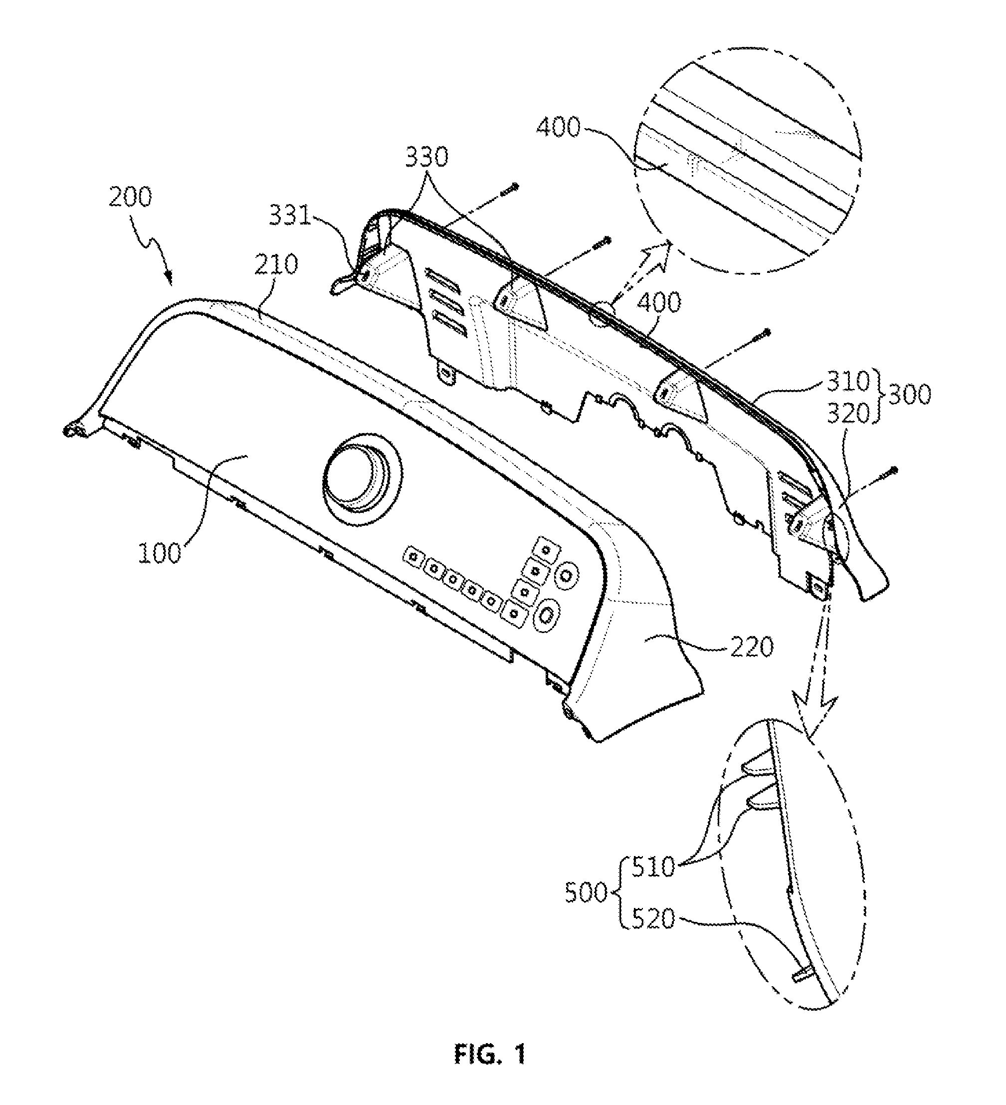
[0041] FIG. 1 is an exploded perspective view showing a casing structure in accordance with embodiments of the present invention for preventing water penetration and a control panel assembly in a washing machine having the same;
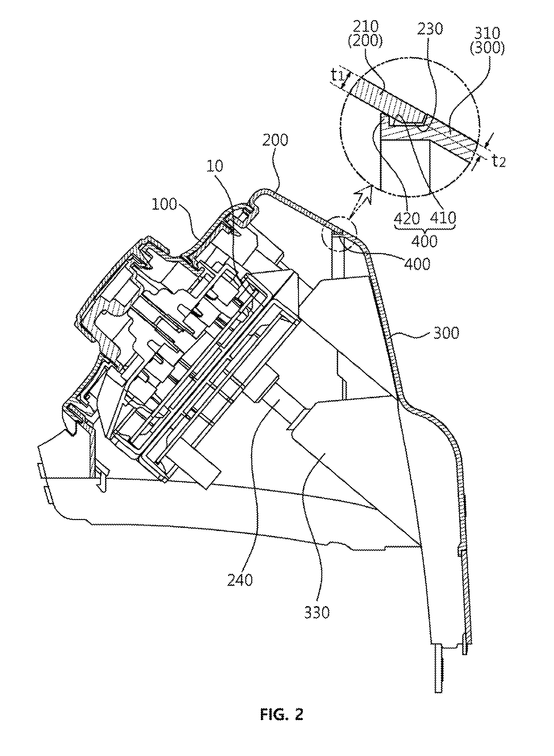
[0042] FIG. 2 is a side cross-sectional view showing the casing structure for preventing water penetration and the control panel assembly in the washing machine having the same, in accordance with embodiments of the present invention; and
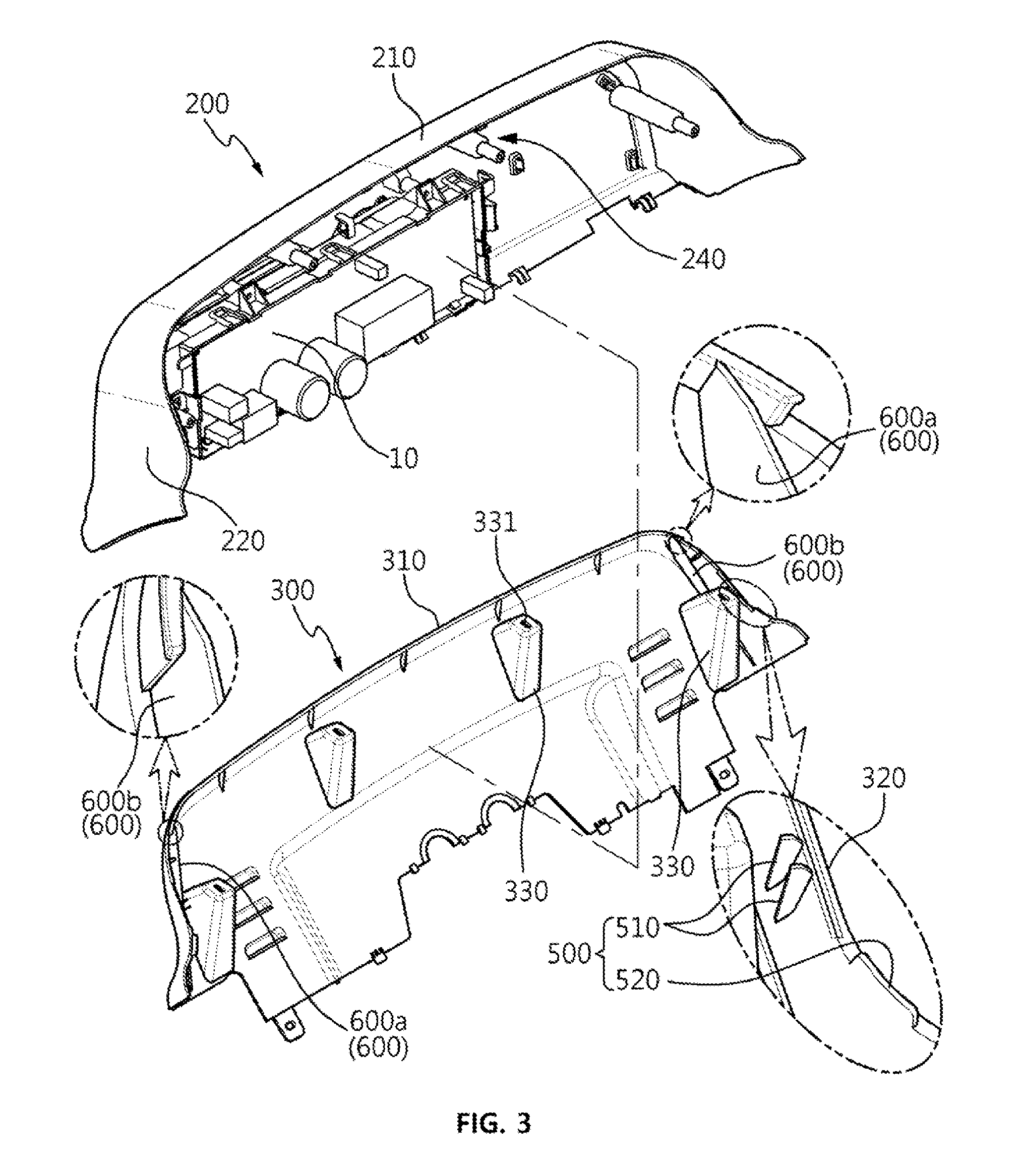
[0043] FIG. 3 is a front cross-sectional view showing the casing structure in accordance with embodiments of the present invention for preventing water penetration and the control panel assembly in the washing machine having the same.
DETAILED DESCRIPTION OF THE INVENTION
[0044] Hereinbelow, the embodiments of the present invention will be described in more detail.
[0045] Exemplary embodiments of the present invention will be described in detail with reference to the accompanying drawings. Terms or words used in the specification and claims are not limited to meaning that is commonly understood by people or is defined in dictionaries, and should be interpreted as having a meaning that is consistent with meaning in the context of the relevant art. Specific structural and functional descriptions of embodiments of the present invention disclosed herein are only for illustrative purposes of the preferred embodiments of the present invention, and the present description is not intended to represent all of the technical spirit of the present invention. On the contrary, the present invention is intended to cover not only the exemplary embodiments, but also various alternatives, modifications, equivalents and other embodiments that may be included within the spirit and scope of the present invention as defined by the appended claims.
[0046] FIG. 1 is an exploded perspective view showing a casing structure for preventing water penetration and a control panel assembly for a washing machine having the same, FIG. 2 is a side cross-sectional view showing the casing structure for preventing water penetration and the control panel assembly in the washing machine having the same, and FIG. 3 is a front cross-sectional view showing the casing structure for preventing water penetration and the control panel assembly in a washing machine.
[0047] Referring to FIGS. 1 to 3, a casing structure for preventing water penetration according to embodiments of the present invention includes a front casing 200 and a rear casing 300 that are detachably coupled to each other and have electrical equipment 10 located therein.
[0048] Furthermore, a control panel assembly in a washing machine according to an embodiment of the present invention includes a control panel 100 including multiple switches for operating functions of the washing machine and a display unit for displaying an operational state of the washing machine, a front casing 200 having the control panel mounted thereon, and a rear casing 300 detachably coupled to the front casing 200.
[0049] The front casing 200 and the rear casing 300 are coupled to each other to define a space therein where the electrical equipment 10 including an electronic PCB substrate and the like for controlling the control panel 10 are located.
[0050] The front casing 200 may include a first upper surface portion 210 and a first side surface portion 220 positioned at each side of the first upper surface portion 210. The rear casing 300 may include a second upper surface portion 210 and a second side surface portion 320 positioned at each side of the second upper surface portion 310.
[0051] It is preferable that each boundary between the first upper surface portion 210 and the first side surface portion 220 is formed in a curved shape to improve the aesthetic appearance of the appliance and to prevent injury to a user.
[0052] Furthermore, it is preferable that each boundary between the second upper surface portion 310 and the second side surface portion 320 is formed in a curved shape to improve aesthetic appearance of the appliance and to prevent user injury.
[0053] A rear edge of the front casing 200 and a front edge of the rear casing 300 are in contact with each other.
[0054] In other words, an end of the first upper surface portion 210 of the front casing 200 and an end of the second upper surface portion 310 of the rear casing 300 are in contact with each other, while ends of opposite first side surface portions 220 of the front casing 200 are in contact with ends of opposite second side surface portions 320 of the rear casing 300.
[0055] Furthermore, as an example, the front casing 200 and the rear casing 300 are detachably coupled to each other by bolts in a configuration where the rear edge and the front edge thereof are in contact with each other, and this will be described in detail below.
[0056] A water movement drainage part 400 is positioned at one edge as between the rear edge of the front casing 200 and the front edge of the rear casing 300 to overlap with a lower portion of the remaining edge.
[0057] The water movement drainage part 400 protrudes from one edge as between the rear edge of the front casing 200 and the front edge of the rear casing 300 to overlap with the lower portion of the remaining edge as between the rear edge of the front casing 200 and the front edge of the rear casing 300, such that water flowing into and between the rear edge of the front casing 200 and the front edge of the rear casing 300 is received therein.
[0058] Furthermore, the water movement drainage part 400 is inclined downward from a central portion to opposite sides thereof to cause water to move to opposite ends thereof for draining.
[0059] The casing structure for preventing water penetration according to embodiments of the present invention may further include a water blocking rib portion 600 standing vertically at a position between an end of the water movement drainage part 400 and the electrical equipment 10 and operates to advantageously block falling water drained through the water movement drainage part 400 from splashing toward the electrical equipment 10.
[0060] The water movement drainage part 400 may stand vertically on at least one of the opposite ends of the water movement drainage part 400 and may integrally protrude from either of an inner surface of the front casing 200 and an inner surface of the rear casing 300.
[0061] The water blocking rib portion 600 may include a first water blocking rib member 600a standing vertically at a position between one end of the water movement drainage part 400 and the electrical equipment 10 and a second water blocking rib member 600b standing vertically at a position between the other end of the water movement drainage part 400 and the electrical equipment 10.
[0062] The water blocking rib portion 600 may stand vertically at a position between each end of the water movement drainage part 400 and the electrical equipment 10, causing falling water drained through the water movement drainage part 400 to be blocked from splashing toward the electrical equipment 10 and thus efficiently and advantageously blocked from penetrating into the electrical equipment 10.
[0063] In FIGS. 1 to 3, the water movement drainage part 400 protrudes from the front edge of the rear casing 300. Accordingly, the water movement drainage part 400 will be described below as protruding from the front edge of the rear casing 300 but may be positioned at the rear edge of the front casing 200, that is, at the end of the first upper surface portion 210, in the same structure as the following description.
[0064] The water movement drainage part 400 may protrude from the end of the second upper surface portion 310 to overlap with a lower portion of the first upper surface portion 210.
[0065] The water movement drainage part 400 may protrude from the end of the first upper surface portion 210 to extend in a width direction of the second upper surface portion 310 to a position corresponding to a length that covers the electrical equipment 10 located beneath.
[0066] More specifically explained, the water movement drainage part 400 extends in the width direction of the second upper surface portion 310 such that at least the opposite ends thereof are greater in length than opposite ends of the electrical equipment 10. This causes water to be directed to fall outwardly of the opposite ends of the electrical equipment 10, e.g., to fall away from the electrical equipment 10.
[0067] The water movement drainage part 400 includes a flow path bottom portion 410 protruding from a lower end of the second upper surface portion 310 which overlaps with a portion of the first upper surface portion 210, and a flow path forming protrusion 420 protruding from an end of the flow path bottom portion 410 to form a flow path.
[0068] The flow path forming protrusion 420 protrudes and supports a lower surface of the first upper surface portion 210, such that when the first upper surface portion 210 is pressed from above, the first upper surface portion 210 is supported thereon. This causes strength to be reinforced at the ends of the first upper surface portion 210 and the second upper surface portion 310 that are in contact with each other.
[0069] The flow path forming protrusion 420 supports a lower surface of the front casing 200 in a configuration in which the rear edge of the front casing 200 and the front edge of the rear casing 300 are in contact with each other, such that an upper surface of the front casing 200 and an upper surface of the rear casing 300 are aligned with each other.
[0070] The flow path forming protrusion 420 is configured such that an upper end thereof is inclined at an inclination angle corresponding to the inclination of the lower surface of the front casing 200, causing a contact area with the lower surface of the front casing 200 to be maximized. This causes the front casing 200 to be stably supported.
[0071] The rear edge of the front casing 200 may be positioned such that at least 50% of the thickness of the front casing 200 is in contact with the front edge of the rear casing 300, and may have a flow path forming inclined surface 230 which inclines from the lower portion thereof to be distanced from an upper surface of the flow path bottom portion 410.
[0072] Since the rear edge of the front casing 200 is positioned such that the at least 50% of the thickness of the front casing 200 makes contact with the front edge of the rear casing 300, this strengthens the joint of the first and second casings 200 and 300 and reduces or minimizes any inflow of water through any gap therebetween.
[0073] The flow path forming inclined surface 230 is distanced from the upper surface of the flow path bottom portion 410 to define a space allowing water (which may flow into a contact portion of the rear edge of the front casing 200 and the front edge of the rear casing 300) to efficiently move along the flow path in opposite directions.
[0074] It is preferable that the flow path forming inclined surface 230 may be inclined in parallel with the upper surface of the flow path bottom portion 410.
[0075] The flow path forming protrusion 420 protrudes to a height greater than the distance between the flow path forming inclined surface 230 and the flow path bottom portion 410. In this configuration, a sufficient flow space is secured for water to flow. The height of the flow path forming protrusion 420 is set at which water moving along the flow path does not leak out through a gap between the upper end of the flow path forming protrusion 420 and the lower surface of the front casing 200.
[0076] A coupling guide rib member 500 may protrude from the inner surface of one edge as between the front casing 200 and the rear casing 300 so as to be supported on the inner surface of the remaining edge.
[0077] The coupling guide rib member 500 may include multiple first rib portions 510 standing vertically and distanced from each other and a long second rib portion 520.
[0078] The first rib portions 510 and the second rib portions 520 protrude to one of the front casing 200 or the rear casing 300 and are supported on the inner surface of the remaining one. This causes the front casing 200 and the rear casing 300 to be supported where the rear edge of the front casing 200 and the front edge of the rear casing 300 are in contact with each other.
[0079] The first rib portions 510 and the second rib portions 520 serve to reinforce the strength of the joint of the first and second casings 200 and 300. These casings are positioned such that the edges thereof are in contact with each other, when the joint is pressed from above, thereby preventing the front and rear casings 200 and 300 from being damaged.
[0080] Furthermore, the front casing 200 has multiple bolt fastening portions 240 formed therein and to which bolts are fastened, and the rear casing 300 has bolt through holes 331 formed therein to correspond to the bolt fastening portions 240.
[0081] The rear casing 300 has multiple bolt fastening protrusions 330 protruding from a bottom surface thereof and having the bolt through holes 331 formed therein, where the bolt fastening protrusions are supported against the bolt fastening portions 240.
[0082] The bolt fastening protrusions 330 protrude inwardly of the rear casing 300 and are in contact with the bolt fastening portions 240 when the front and rear casings 200 and 300 are coupled in contact with each other, causing the front and rear casings 200 and 300 to be supported in a coupling position.
[0083] In other words, the front casing 200 and the rear casing 300 are in contact with each other while the bolt fastening portions 240 are positioned corresponding to the bolt through holes 331. The bolts are inserted into the bolt through holes 331 to be fastened to the bolt fastening portions 240, causing the front and rear casings to be coupled to each other.
[0084] Herein, the rear edge of the front casing 200 is in contact with the front edge of the rear casing 300, and the first rib portions 510 and the second rib portions 520 support the inner surface of either of the front casing 200 or the rear casing 300. This causes the rear edge of the front casing 200 and the front edge of the rear casing 300 to be in close contact with each other, while an outer surface of the front casing 200 and an outer surface of the rear casing 300 are aligned with each other, making it possible to prevent misalignment from occurring at the joint of the front casing 200 and the rear casing 300.
[0085] Furthermore, the water movement drainage part 400 is positioned to partially overlap with the lower surface of the front casing 200, causing water flowing into between the rear edge of the front casing 200 and the front edge of the rear casing 300 to flow into the flow path.
[0086] Furthermore, the flow path forming protrusion 420 of the water transfer member 400 closely contacts the lower surface of the front casing 200, making it possible to prevent misalignment of the front casing 200 and the rear casing 300 from occurring while also preventing water in the flow path from leaking out.
[0087] In other words, water flowing between the rear edge of the front casing 200 and the front edge of the rear casing 300 is collected and stored in the flow path of the water movement drainage part 400 and will flow to the opposite sides of the front casing 200 and fall away from the electrical equipment 10. This advantageously prevents water from penetrating into the electrical equipment 10 located inside the casings.
[0088] The control panel assembly in the washing machine according to embodiments of the present invention causes water (which splashes to the outside thereof and flows into and between the rear edge of the front casing 200 and the front edge of the rear casing 300 during washing preparation or washing) to flow toward the water movement drainage part 400 and to locations that do not affect the electrical equipment 10 of the control panel 100. This makes it possible to efficiently block water from penetrating into the electrical equipment 10 of the control panel 100.
[0089] Embodiments of the present invention effectively prevent water from penetrating into the electrical equipment 10 located inside the casings and thereby prevent malfunction or failure of the electrical equipment 10. In particular, the embodiments of the present invention improve the durability of a washing machine appliance while also improving reliability.
[0090] The embodiments of the present invention can simplify the coupling structure of the casings to strengthen the mold used to manufacture the casings, resulting in reductions in manufacturing costs and in manufacturing defect rates.
[0091] Furthermore, the embodiments of the present invention can reduce misalignment that may occur at the joint of the casings while increasing the strength of the joint to improve durability, resulting in a significant improvement of the reliability of the washing machine appliance.
[0092] Although a preferred embodiment of the present invention has been described for illustrative purposes, those skilled in the art will appreciate that various modifications, additions and substitutions are possible, without departing from the scope and spirit of the invention as disclosed in the accompanying claims.
* * * * *
D00000
D00001
D00002
D00003
XML
uspto.report is an independent third-party trademark research tool that is not affiliated, endorsed, or sponsored by the United States Patent and Trademark Office (USPTO) or any other governmental organization. The information provided by uspto.report is based on publicly available data at the time of writing and is intended for informational purposes only.
While we strive to provide accurate and up-to-date information, we do not guarantee the accuracy, completeness, reliability, or suitability of the information displayed on this site. The use of this site is at your own risk. Any reliance you place on such information is therefore strictly at your own risk.
All official trademark data, including owner information, should be verified by visiting the official USPTO website at www.uspto.gov. This site is not intended to replace professional legal advice and should not be used as a substitute for consulting with a legal professional who is knowledgeable about trademark law.