Process For Producing Lighter Distillates
Raja; Kanuparthy Naga ; et al.
U.S. patent application number 16/347785 was filed with the patent office on 2019-10-31 for process for producing lighter distillates. The applicant listed for this patent is HINDUSTAN PETROLEUM CORPORATION LTD. Invention is credited to Sriganesh Gandham, Venkateswarlu Choudary Nettem, Venkata Chalapathi Rao Peddy, Satyanarayana Murty Pudi, Kanuparthy Naga Raja, Bhavesh Sharma.
| Application Number | 20190330543 16/347785 |
| Document ID | / |
| Family ID | 62075548 |
| Filed Date | 2019-10-31 |


| United States Patent Application | 20190330543 |
| Kind Code | A1 |
| Raja; Kanuparthy Naga ; et al. | October 31, 2019 |
PROCESS FOR PRODUCING LIGHTER DISTILLATES
Abstract
The present subject matter relates to a process of producing lighter distillates. The hydrocarbons in the presence of organometallic catalyst are reacted with hydrogen leading to hydrotreating and/or hydrocracking reactions. The metals present in product are subsequently captured the metal capture unit.
| Inventors: | Raja; Kanuparthy Naga; (Hoskote, Karnataka, Bangalore, IN) ; Sharma; Bhavesh; (Hoskote, Karnataka, Bangalore, IN) ; Pudi; Satyanarayana Murty; (Hoskote, Karnataka, Bangalore, IN) ; Peddy; Venkata Chalapathi Rao; (Hoskote, Karnataka, Bangalore, IN) ; Nettem; Venkateswarlu Choudary; (Hoskote, Karnataka, Bangalore, IN) ; Gandham; Sriganesh; (Hoskote, Karnataka, Bangalore, IN) | ||||||||||
| Applicant: |
|
||||||||||
|---|---|---|---|---|---|---|---|---|---|---|---|
| Family ID: | 62075548 | ||||||||||
| Appl. No.: | 16/347785 | ||||||||||
| Filed: | November 7, 2017 | ||||||||||
| PCT Filed: | November 7, 2017 | ||||||||||
| PCT NO: | PCT/IN2017/050514 | ||||||||||
| 371 Date: | May 6, 2019 |
| Current U.S. Class: | 1/1 |
| Current CPC Class: | C10G 47/02 20130101; C10G 45/08 20130101; C10G 2300/4093 20130101; C10G 2400/04 20130101; C10G 2300/706 20130101; C10G 2400/06 20130101; C10G 31/10 20130101; C10G 47/00 20130101; C10G 49/02 20130101; C10G 2300/301 20130101; C10G 45/02 20130101; C10G 25/00 20130101; C10G 45/16 20130101; C10G 45/10 20130101; C10G 2400/02 20130101; C10G 47/14 20130101; C10G 2300/1055 20130101; C10G 45/04 20130101 |
| International Class: | C10G 45/16 20060101 C10G045/16; C10G 45/10 20060101 C10G045/10; C10G 45/08 20060101 C10G045/08; C10G 47/14 20060101 C10G047/14 |
Foreign Application Data
| Date | Code | Application Number |
|---|---|---|
| Nov 7, 2016 | IN | 201621038025 |
Claims
1. A process for hydroprocessing of hydrocarbons, said process comprising the following steps: i. mixing the hydrocarbon feed and an organometallic catalyst to obtain a combined feed; ii. hydroprocessing said combined feed under hydrogen atmosphere in a reactor at a temperature in the range of 100.degree. C. to 450.degree. C. and at a pressure in the range of 10 bar to 250 bar to obtain a product stream; iii. transferring said product stream to a metal capture unit to separate the metals from the product stream; iv. sending relatively metal free product stream obtained in step (iii) to first separator for the separation of gas and liquid products; v. transferring the liquid product stream separated out in step (iv) to second separator for further separation of gas and liquid products; and vi. sending the liquid products separated out in step (v) to a fractionator for obtaining various fractions of the hydroprocessed product.
2. The process as claimed in claim 1, wherein said hydrocarbon feed comprises of hydrocarbons boiling above 60.degree. C., ranging from Naphtha to Vacuum Gas Oil.
3. The process as claimed in claim 1, wherein said catalyst comprises at least one metal or a metallic compound of said metal selected from the group consisting of chromium, manganese, iron, cobalt, nickel, zirconium, niobium, molybdenum, tungsten, ruthenium, rhodium, tin, and tantalum.
4. The process as claimed in claim 1, wherein the amount of said catalyst is in the range of 0.001 wt % to 10 wt % of said hydrocarbon feed.
5. The process as claimed in claim 1, wherein in the process step (ii), hydroprocessing is carried out for a time period in the range of 15 minutes to 4 hours.
6. The process as claimed in claim 1, wherein in the process step (ii), the said reactor system can be selected from a group consisting of continuous stirred tank reactor, ebullated bed reactor, slurry bubble column reactor or combinations thereof.
7. The process as claimed in claim 1, wherein the metal capture unit is placed at the downstream of first separator.
8. The process as claimed in claim 1, wherein the metal capture unit is placed at the downstream of second separator.
9. The process as claimed in claim 1, wherein a portion of captured metal stream is recycled back to the reactor system while the remaining portion is sent for metal recovery.
10. The process as claimed in claim 1, wherein the metal capture unit is one of a centrifuge unit and an adsorption unit.
Description
TECHNICAL FIELD
[0001] The present subject matter relates to hydroprocessing and, in particular, to a process for hydroprocessing distillates in the range of naphtha to vacuum gas oils in slurry phase.
BACKGROUND
[0002] Hydroprocessing is widely used to improve quality of products obtained during crude oil refining. For instance, hydrotreating is carried out to remove Sulfur and Nitrogen from hydrocarbon feedstock in treating units. Similarly, hydrocracking is carried out to convert heavy hydrocarbons into lighter and more valuable hydrocarbons. Hydrotreating and hydrocracking reactions are generally carried out in fixed bed reactors. Solid catalysts of different shapes are loaded into the fixed bed reactors to form number of beds separated by a quench system to carry out the reactions for Hydroprocessing.
BRIEF DESCRIPTION OF DRAWINGS
[0003] The detailed description is described with reference to the accompanying figures. In the figures, the left-most digit(s) of a reference number identifies the figure in which the reference number first appears. The same numbers are used throughout the drawings to reference like features and components.
[0004] FIG. 1 illustrates a block diagram of a hydroprocessing unit, in accordance with an example of the present subject matter.
[0005] FIG. 2 illustrates a block diagram of a hydroprocessing unit, in accordance with another example of the present subject matter.
[0006] FIG. 3 illustrates a block diagram of a hydroprocessing unit, in accordance with yet another example of the present subject matter.
[0007] FIG. 4 illustrates a block diagram of a hydroprocessing unit, in accordance with yet another example of the present subject matter.
[0008] FIG. 5 illustrates a method for producing lighter distillates in a hydroprocessing unit, in accordance with yet another example of the present subject matter.
DETAILED DESCRIPTION
[0009] In conventional hydroprocessing fixed bed reactors, solid catalysts are arranged to form fixed beds. During operation, hydrocarbon feed is allowed to flow through the catalyst beds. As the feed reaches the pores of the catalyst, reaction takes place between the hydrocarbons and hydrogen gas in presence of the active metals in the catalysts. The after-products of the reaction subsequently flow out and exit the reactor for further downstream processing. As the fixed bed reactors require the feed to flow across the catalyst surface and catalyst pores before reaching the active metals for reaction, the feed usually faces resistance from the catalyst surface and the catalyst pores. Further, due to the regular reactions occurring over the catalyst, coke formation may take place, owing to which the pores may get blocked. The feed may thus not be able to freely access the active metals on the catalyst. Further, flow maldistribution of the feed may occur due to dead zones and channeling within the fixed bed reactors, thus, limiting the extent of reaction, thereby affecting the efficiency of hydroprocessing.
[0010] The present subject matter describes a process of producing lighter distillates. In one example, the process includes hydroprocessing of hydrocarbons in the range of naphtha to vacuum gas oils in slurry phase. In one example implementation, the lighter distillates are produced by performing hydrotreating and/or hydrocracking reactions in a hydroprocessing unit. The hydroprocessing unit is to carry out hydroprocessing reactions in a slurry phase with active catalysts in dispersed mode. In one implementation, the active catalyst may be an organometallic based catalyst comprising a metal selected from a predetermined group of metals.
[0011] In one embodiment of the present subject matter, the organometallic based catalyst may comprise a metal selected from the group consisting of titanium, molybdenum, vanadium, chromium, manganese, iron, cobalt, nickel, zirconium, tungsten, ruthenium, rhodium, tin, tantalum, rhenium, and iridium. In one implementation, the amount of metal in the catalyst used for hydroprocessing of the hydrocarbons may be in the range of 0.001% to 10% by weight.
[0012] In one example, the hydroprocessing unit includes a reactor system, a feed vessel for providing feed to the reactor system, a catalyst storage tank for providing a catalyst to the feed vessel, separators for separation of gaseous and liquid products obtained from the reactor system, and a fractionator for separation of different fractions of the product. In one implementation, the reactor system can be selected from a group consisting of continuous stirred tank reactor, ebullated bed reactor, slurry bubble column reactor or combinations thereof. In one another implementation, the reactor system comprises of reactors in a configuration selected from the group consisting of series, parallel and series-parallel.
[0013] During operation, a predetermined amount of the organometallic based catalyst may be mixed with a predetermined amount of the hydrocarbon feed present in the feed vessel. The mix of organometallic based catalyst and the hydrocarbon feed may then be provided along with Hydrogen gas to the reactor system at a predetermined pressure. The hydrocarbon feed and the Hydrogen gas is then allowed to react in presence of the active metals in the catalysts at a predetermined temperature and pressure, for a predetermined time period. The products, thus obtained are processed by the separators to separate gaseous and liquid products and further remove dissolved gases from the liquid products. Subsequently, the liquid products are provided to the fractionator for fractionation to obtain different products. Further, metal capture units can be used to capture and re-use the metal from the catalyst, as will be described in detail with reference to the figures.
[0014] The present subject matter thus provides a process of producing lighter distillates in the range of naphtha to vacuum gas oils in slurry phase. The distillates are produced in a hydroprocessing unit that facilitates hydroprocessing of hydrocarbon feedstocks in a slurry phase with active catalysts in dispersed mode. Hydroprocessing the feedstock in a slurry phase instead of a fixed bed reactor helps in providing efficient reaction between the hydrocarbon feedstock and the hydrogen gas in the presence of the active metal in the active catalyst. As the active catalyst is dispersed in the liquid hydrocarbon feedstock to form a slurry, the feedstock is efficiently able to come in contact with the metal.
[0015] The present subject matter is further described with reference to FIGS. 1 to 5. It should be noted that the description and figures merely illustrate principles of the present subject matter. Various arrangements may be devised that, although not explicitly described or shown herein, encompass the principles of the present subject matter. Moreover, all statements herein reciting principles, aspects, and examples of the present subject matter, as well as specific examples thereof, are intended to encompass equivalents thereof.
[0016] FIG. 1 illustrates a block diagram of a hydroprocessing unit 102, in accordance with an example of the present subject matter. In one example, the hydroprocessing unit 102 includes a catalyst storage tank 104, a feed vessel 106, a reactor system 108, a first separator 110, a second separator 112, and a fractionator 114. Although, the hydroprocessing unit 102 may include various other intermediate sub-units that may be utilized for hydroprocessing, however, for the sake of brevity and not as a limitation, only the aforementioned sub-units are described and shown in the figure.
[0017] The reactor system 108 is in fluid connection with the feed vessel 106 and the first separator 110. In one implementation, the first separator 110 is a high-pressure separator and the second separator 112 is a low-pressure separator. Further, a hydrogen gas supply unit 116 may be connected to the reactor system 108 for providing the hydrogen for hydroprocessing.
[0018] As previously described, the hydroprocessing unit 102 may be implemented for performing hydrotreating and/or hydrocracking reactions of hydrocarbon feedstock ranging from naphtha to vacuum gas oil. For example, the hydrocarbon feed comprises of hydrocarbons boiling above 60.degree. C. In one implementation, the hydroprocessing unit 102 may use an organometallic based catalyst comprising a metal selected from the group consisting of titanium, molybdenum, vanadium, chromium, manganese, iron, cobalt, nickel, zirconium, tungsten, ruthenium, rhodium, tin, tantalum, rhenium, and iridium. In one implementation, the amount of metal in the catalyst used for hydrotreating the hydrocarbons may be in the range of 0.001% to 10% by weight. Further, the metal content in the catalyst may range from 1% to 35%.
[0019] Further, the hydroprocessing unit 102 may be operated at a temperature in the range of 100.degree. C. to 450.degree. C. depending on the feed and the catalyst. The hydroprocessing unit 102 may be operated at a pressure in the range of 10 bar to 250 bar depending on the feed and the catalyst.
[0020] In operation, initially, a predetermined amount of an organometallic based catalyst is obtained from the catalyst storage tank 104 and mixed with a predetermined amount of feed obtained from the feed vessel 106. In one implementation, the catalyst and the feed may be mixed in one of a static line mixer (not shown in the figure) or a mixing tank (not shown in the figure) before the mix enters into the reactor system 108. The mix of catalyst and the feed may then be transferred to the reactor system 108. Further, the hydrogen gas may be fed to the reactor system 108 at a predetermined pressure. The feed and the hydrogen gas subsequently react in the presence of the catalyst at a predetermined temperature for a predetermined time period. For example, the reaction may be carried out under hydrogen atmosphere at a temperature in the range of 100.degree. C. to 450.degree. C. and at a pressure in the range of 10 bar to 250 bar for a time ranging from 15 minutes to 4 hours.
[0021] As a result of the high temperature reaction conditions, the organometallic catalyst decomposes to release the active metal. The metal in the reactant mixture acts as the catalyst for hydroprocessing resulting in the cracking of heavy hydrocarbons into lighter distillates.
[0022] A product stream having the products obtained as a result of the reaction is subsequently transferred to the first separator 110 to separate gas products and liquid products. The separation happens by virtue of Thermodynamic flash at predetermined temperature and pressure maintained within the first separator 110. In one example, the first separator is operated in a temperature range of 200 to 250 deg C. and in a Pressure range of 180-200 bar.
[0023] In one example, the gas products may include dry gas and LPG. Dry gas may be routed to hydrogen recovery section for hydrogen separation. The recovered hydrogen may be recycled back to the reaction zone. The liquid products are further transferred to the second separator 112 to remove dissolved gases from the liquid products. The gases, thus obtained, are then removed from the second separator 112 for further treatment, while the liquid products are moved to the fractionator 114. The separation in the second separator 112 happens by virtue of Thermodynamic flash at predetermined temperature and pressure maintained within the second separator 112. In one example, the second separator 112 is operated in a temperature range of 25 to 30 deg C. and in a Pressure range of 1-2 bar.
[0024] The fractionator 114 may perform fractionation to separate product fractions from the liquid product based on their boiling point range to obtain various fractions of the product. In one example, the products obtained from fractionator may be mixtures of Naphtha, Kerosene, Diesel, and Vacuum Gas Oil. The operating conditions of the fractionator can be appropriately selected depending on the products to be obtained, as will be understood.
[0025] In the above described process, the metal from the catalyst remains in the liquid product streams that are taken out from the different separators. The present subject matter provides for metal capture, such as using adsorption or centrifugation, for separating out the metals from the hydroprocessed products. The metals adsorbed on the adsorbents may be further put to re-use as a catalyst in the reactor leading to a reduction in the requirement of make-up catalyst. Further, the amount of metal discarded as waste is substantially reduced. Various example schemes for metal capture will now be described.
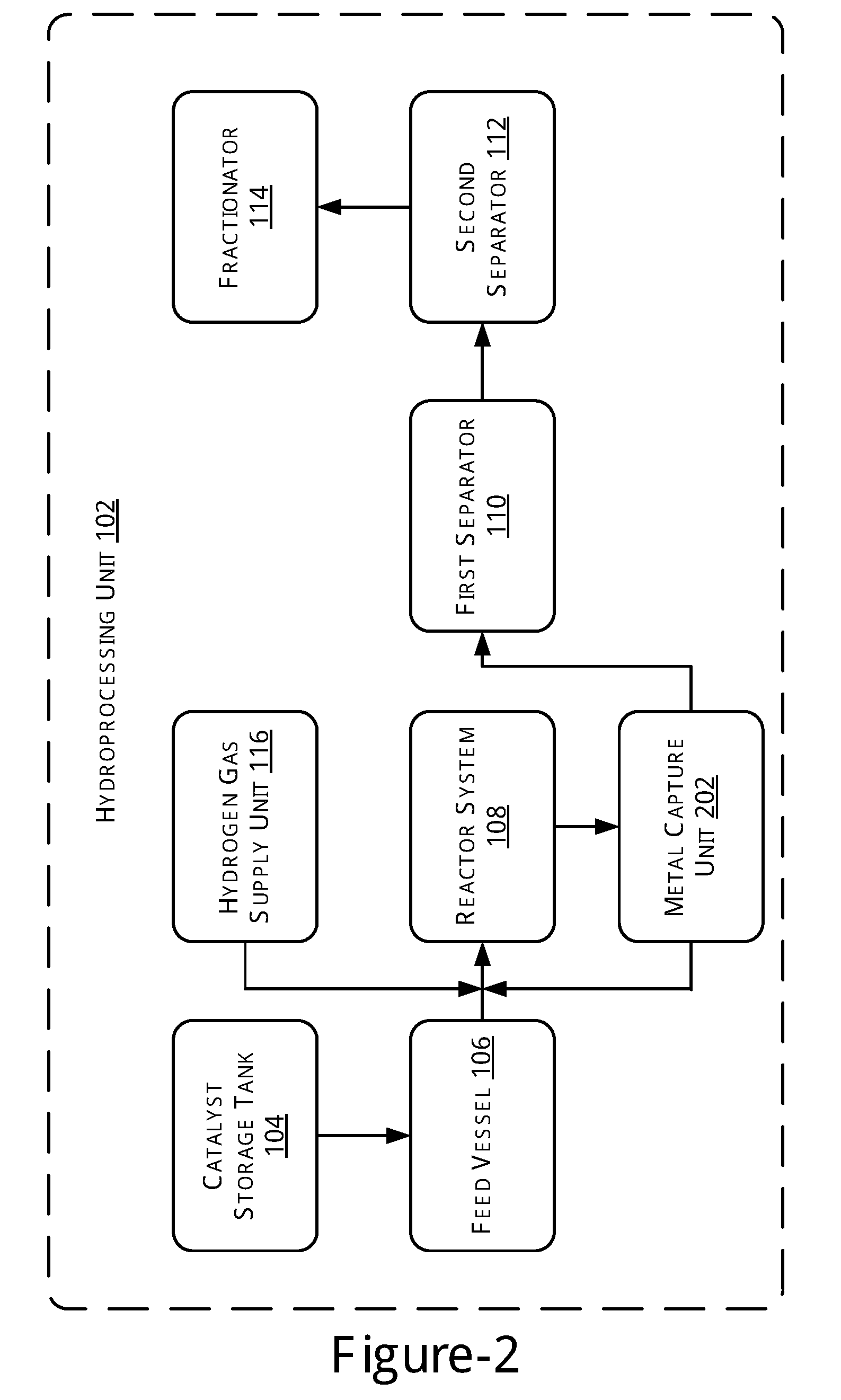
[0026] FIG. 2 illustrates a block diagram of the hydroprocessing unit 102, in accordance with another example of the present subject matter. As illustrated, the hydroprocessing unit 102 in accordance with the current embodiment further includes a metal capture unit 202 coupled to the reactor system 108. The metal capture unit 202 is provided to remove metals from the products obtained from the reactor system 108.
[0027] In operation, initially, a predetermined amount of a catalyst is obtained from the catalyst storage tank 104 and mixed with a predetermined amount of feed obtained from the feed vessel 106. The mix of catalyst and the feed may then be transferred to the reactor system 108. Further, the hydrogen gas may be transferred to the reactor system 108 at a predetermined pressure. The feed and the hydrogen gas may then be allowed to react in the presence of the catalyst at a predetermined temperature for a predetermined time period.
[0028] A product stream having the products obtained as a result of the reaction is subsequently transferred to the metal capture unit 202. The metal capture unit 202 may implement a separation process for separating metals from the product stream. In one implementation, the separation process may be one of an adsorption process and a centrifugal process.
[0029] For the separation process being a centrifugal process, the metal capture unit 202 may be implemented as a centrifuge. The metal capture unit 202 may thus perform the separation process such that the product stream is separated into a lighter portion stream and a heavier portion stream. The heavier portion stream that includes the metals may be transferred back to the reactor system 108 while the lighter portion stream is transferred to the first separator 110 for the separation of gas and liquid products.
[0030] For the separation process being an adsorption process, the metal capture unit 202 may be implemented as an adsorption unit employing an adsorption bed with active adsorbents. As the product stream is received by the metal capture unit 202, the metals are adsorbed on the adsorbents. The adsorption may occur as a result of one or both of physical adsorption and chemical adsorption.
[0031] A relatively metal free hydrocarbon product stream, thus obtained, is transferred to the first separator 110. A metal loaded stream of adsorbents obtained owing to the adsorption may be transferred to the reactor system 108 as an additional catalyst for the reactions. In one example, a portion of the metal loaded stream of adsorbents may be recycled to the reactor while the other portion may be sent for metal recovery. The ratio of the metal loaded stream recycled may depend on the extent of adsorption which occurs and can be changed suitably as will be understood.
[0032] In the metal recovery process, the metal from the metal loaded adsorbents may be leached away, for example, by contact with a hydrocarbon. In one example, the leaching may be performed using fresh diesel. The recovered metal may be again used in the reaction or may be used as reclaimed metal.
[0033] After the reaction, the product stream from the reactor 108 may be sent to a filtration system (not shown in diagram) to remove spent adsorbents, i.e., metal loaded adsorbents, before transferring to metal capture unit 202, which is filled with fresh adsorbents. Alternatively, the metal loaded adsorbents may be regenerated to reclaim metals without being transferred to the reactor system 108.
[0034] The adsorbent employed in the metal capture unit may employ any commercial adsorbent that can adsorb the metals and can be selected from a group consisting of activated carbon derived from hard woods, soft woods and rice husks, functionalized activated carbon obtained from refinery residues like delayed coker pitch, slurry hydrocracking pitch and Bituminous tar, lignite coal, ion-exchange resins, carbon nanotubes, graphene, carbon black, functionalized carbon obtained after carbonization of rubber tires and coconut coir, zeolites, alumino-silicates, silica light, ZSM-5, modernite, carbon molecular sieves and clays such as bentonite and kaolin.
[0035] On receiving the product stream after metal capture, which is either the relatively metal free hydrocarbon product stream or the lighter portion stream, the first separator 110 processes the product stream to separate gas products and liquid products. The liquid products are further transferred to the second separator 112 to remove dissolved gases from the liquid products. The gases, thus obtained, are then removed from the second separator 112 for further treatment, while the liquid products are moved to the fractionator 114. The fractionator 114 may perform fractionation to separate product fractions from the liquid product based on their boiling point range to obtain various distillates. The operating conditions of the various units, such as reactor, separators, and fractionator, may be similar to those described earlier.
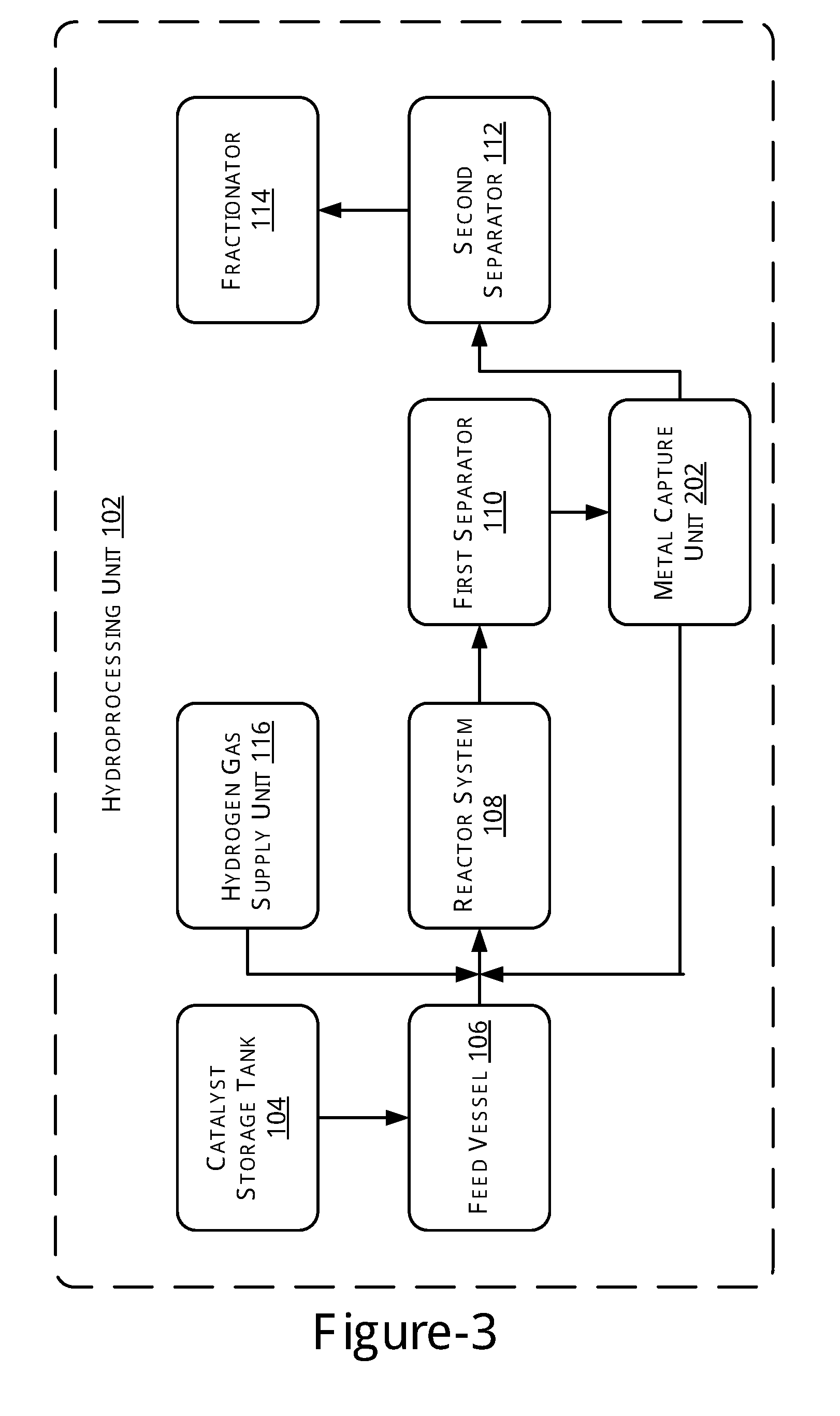
[0036] FIG. 3, illustrates a block diagram of the hydroprocessing unit 102, in accordance with yet another example of the present subject matter. As illustrated, the hydroprocessing unit 102 in accordance with the current embodiment, further includes the metal capture unit 202 coupled to the first separator 110 and the reactor system 108. In said embodiment, the metal capture unit 202 is provided to remove metals from the liquid products obtained from the first separator 110.
[0037] Thus, in this scheme, metal capture is conducted after the separation of the lighter fractions from the hydroprocessed products. Metal removal thus happens from the heavier portion left behind after the separation of lighters. The operating conditions of the various units, such as reactor, separators, and fractionator, may be similar to those described earlier.
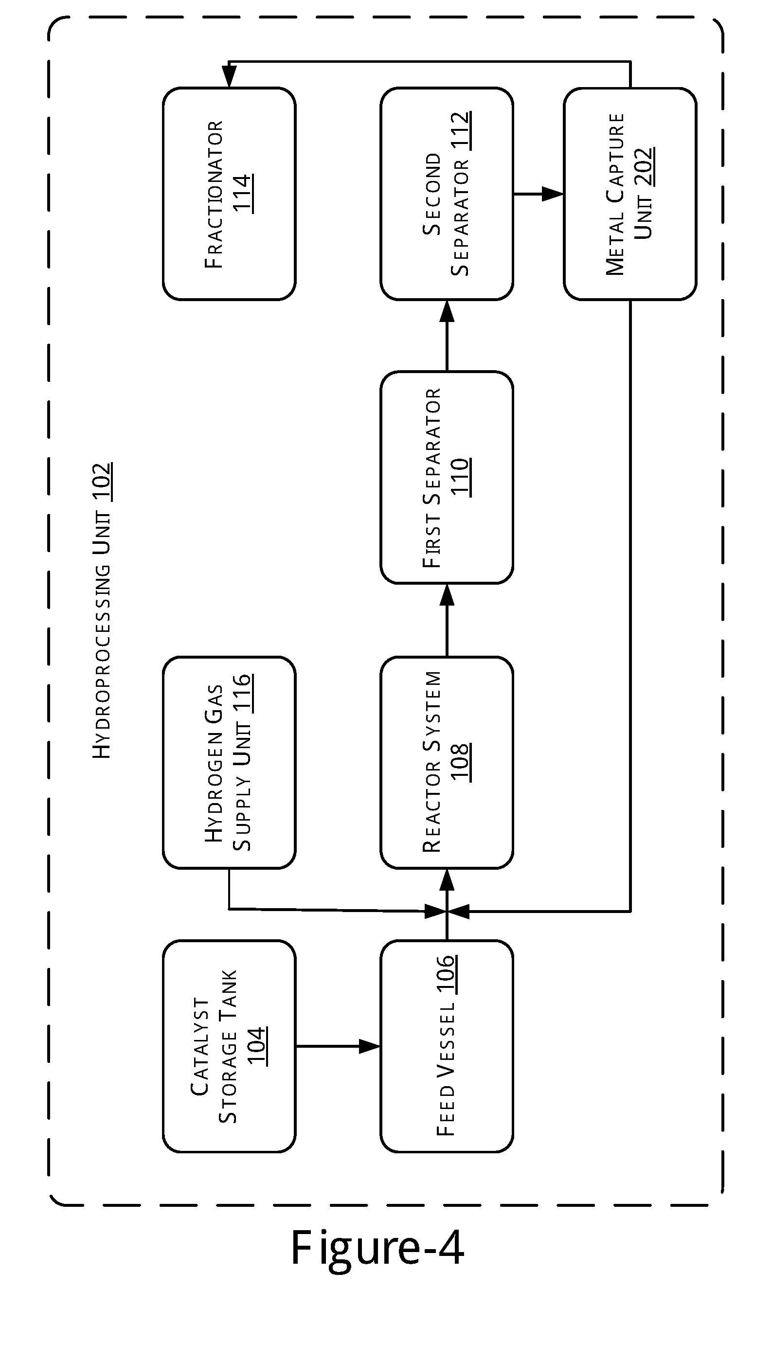
[0038] FIG. 4 illustrates a block diagram of the hydroprocessing unit 102, in accordance with yet another example of the present subject matter. As illustrated, the hydroprocessing unit 102 in accordance with the current embodiment, further includes the metal capture unit 202 coupled to the second separator 112, the reactor system 108, and the fractionator 114. In said embodiment, the metal capture unit 202 is provided to remove metals from the liquid products obtained from the second separator 112.
[0039] Thus, in this scheme, metal capture is conducted after the further separation of the lighter fractions from the hydroprocessed products. Metal removal is done here after most of the volatile or lighter fractions have been separated out from the heavier portion left behind. The operating conditions of the various units, such as reactor, separators, and fractionator, may be similar to those described earlier.
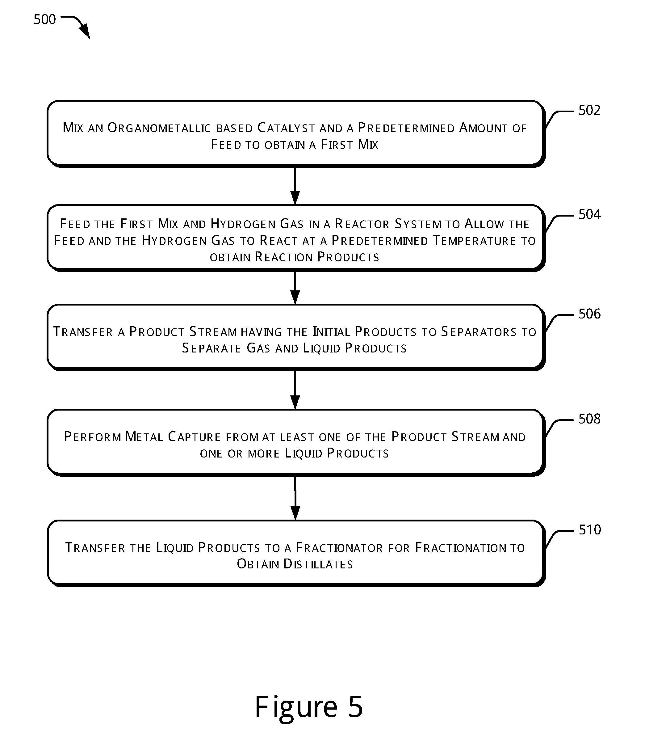
[0040] FIG. 5 illustrates a method 500 for producing lighter distillates in a hydroprocessing unit, in accordance with yet another example of the present subject matter.
[0041] The order in which the method 500 is described is not intended to be construed as a limitation, and any number of the described method blocks may be combined in any order to implement the aforementioned methods, or an alternative method. Further, the method may be performed in a hydroprocessing unit, such as the hydroprocessing unit 102.
[0042] At block 502, an organometallic based catalyst and a predetermined amount of feed are mixed to obtain a first mix. In one example, the organometallic based catalyst comprising a metal selected from the group consisting of titanium, molybdenum, vanadium, chromium, manganese, iron, cobalt, nickel, zirconium, tungsten, ruthenium, rhodium, tin, tantalum, rhenium, and iridium. Further, the feed may be a hydrocarbon feed. The catalyst and the feed may be mixed in one of a static line mixer (not shown in the figure) or a mixing tank (not shown in the figure).
[0043] At block 504, the first mix and hydrogen gas are fed in a reactor system. The hydrogen may be mixed with the first mix before entering into the reactor system. The hydrogen gas and the feed are allowed to react in the presence of the catalyst at a predetermined temperature to obtain reaction products. In one example, the temperature may be maintained in the range of 100.degree. C. to 450.degree. C.
[0044] At block 506, a product stream having the reaction products is transferred to separators to obtain gaseous and liquid products. In one example, the liquid products are further processed to separate gas dissolved in the liquid products.
[0045] At block 508, metal may be captured from at least one of the product stream and one or more liquid product streams, for example, as per the schemes described in FIGS. 2-4 earlier.
[0046] At block 510, the liquid products are transferred to a fractionator for fractionation. In one example, the fractionator may perform fractionation to separate product fractions from the liquid product to obtain lighter distillates including Naphtha, Kerosene, Diesel, and Vacuum Gas Oil.
EXAMPLES
[0047] The present subject matter will now be illustrated with working examples, which are intended to illustrate the working of disclosure and not intended to be taken restrictively to imply any limitations on the scope of the present disclosure. Unless defined otherwise, all technical and scientific terms used herein have the same meaning as commonly understood to one of ordinary skill in the art to which this disclosure belongs. It is to be understood that this disclosure is not limited to the particular methods and experimental conditions described, as such methods and conditions may vary depending on the process and inputs used as will be easily understood by a person skilled in the art.
Example 1: Slurry Phase Diesel Hydrotreating with No Catalyst
[0048] The example 1 illustrates the slurry phase hydrotreating of sour diesel in the presence of hydrogen without catalyst. In said example, 300 ml of sour diesel was taken in a batch reactor. The reactor was purged with nitrogen to remove any air trapped inside and later it was pressurized with Hydrogen to attain a pressure of 40 bar. The reaction mixture was heated to 340.degree. C., under continuous stirring at 500 rpm. The reaction temperature was maintained for 1 hour. After 1 hour, chilled water was circulated to bring down the temperature to 30.degree. C. The gaseous products were collected in a gas bomb. The liquid sample was collected and analyzed in Micro Distillation Unit as per ASTM D-7345. Density measurement and Sulphur analysis was also conducted for both the feed diesel as well as the products. The results of the experiment of example 1 are summarized in Tables 1 and 2, as shown herein:
TABLE-US-00001 TABLE 1 Results for Sulphur content and density for the feed diesel and the product Property Feed Product Density at 15.degree. C. 0.85505 g/m.sup.3 0.85476 g/m.sup.3 Sulphur content 1.65 wt % 1.53 wt %
TABLE-US-00002 TABLE 2 Results for micro distillation for the feed and product Feed Product Initial Boiling Point (IBP) 228.5.degree. C. 230.4.degree. C. 95% 377.8.degree. C. 380.4.degree. C.
[0049] As illustrated, there is a small reduction in the Sulphur content of the product as is observed from the Sulphur analysis.
Example 2: Slurry Phase Diesel Hydrotreating at 40 Bar Pressure of Hydrogen with Iron-Based Catalyst
[0050] The example 2 illustrates the slurry phase hydrotreating of sour diesel in the presence of hydrogen using SCAT-106* as a catalyst precursor which is an Iron-based organometallic catalyst. In said example, 300 ml of sour diesel and 1000 ppm of SCAT-106* were taken in a batch reactor. The reactor was purged with nitrogen to remove any air trapped inside and later it was pressurized with Hydrogen to attain a pressure of 40 bar. The reaction mixture was heated to 340.degree. C., under continuous stirring at 500 rpm. Heating was continued for 1 hour. After 1 hour, the reaction was quenched by circulating chilled water to bring down the temperature to 30.degree. C. The gaseous products were collected in a gas bomb. The liquid sample was collected and analyzed in Micro Distillation Unit as per ASTM D-7345. Density measurement and Sulphur content analysis were also conducted for both the feed diesel as well as the products. The results of the experiment of example 2 are summarized in Tables 3 and 4, as shown herein:
TABLE-US-00003 TABLE 3 Results for Sulphur content and density for the feed diesel and the product Property Feed Product Density at 15.degree. C. 0.85505 g/m.sup.3 0.84828 g/m.sup.3 Sulphur content 1.65 wt % 1.46 wt %
TABLE-US-00004 TABLE 4 Results for micro distillation for the feed and product Feed Product IBP 228.5.degree. C. 226.2.degree. C. 95% 377.8.degree. C. 379.3.degree. C.
[0051] As illustrated, the Sulphur removal is more with the addition of catalyst as compared to the reaction without the use of a catalyst.
Example 3: Slurry Phase Diesel Hydrotreating at 60 Bar Pressure of Hydrogen with Molybdenum-Based Catalyst
[0052] The example 3 illustrates the slurry phase hydrotreating of sour diesel in the presence of hydrogen using SOSCAT-9 as a catalyst which is a Molybdenum-based organometallic catalyst. In said example, 50 grams of sour diesel, 10000 ppm of SOSCAT-9 and 0.5 g of Dimethyl disulfide (for sulfiding of the catalyst) was taken in a batch reactor. The reactor was purged with nitrogen to remove any air trapped inside and later it was pressurized with Hydrogen to attain a pressure of 60 bar. For pre-sulfidation of the catalyst, the reactor with the reaction mixture was heated to a temperature of about 320.degree. C. The reaction mixture was then cooled down and the reactor was de-pressurized. The reaction mixture was again heated to 340.degree. C., under continuous stirring at 500 rpm after re-pressurizing the reactor to 60 bar Hydrogen Pressure. Heating was continued for 1 hour. After 1 hour, the reaction was quenched by circulating chilled water to bring down the temperature to 30.degree. C. The gaseous products were collected in a gas bomb. The liquid sample was collected and analyzed in Micro Distillation Unit as per ASTM D-7345. Density measurement and Sulphur content analysis were also conducted for both the feed diesel as well as the products. The results of the experiment of example 3 are summarized in Tables 5 and 6, as shown herein:
TABLE-US-00005 TABLE 5 Results for Sulphur content and density for the feed diesel and the product Property Feed Product Density at 15.degree. C. 0.85505 g/m.sup.3 0.8273 g/m.sup.3 Sulphur content 1.65 wt % 200 ppm
TABLE-US-00006 TABLE 6 Results for micro distillation for the feed and product Feed Product IBP 228.5.degree. C. 115.6.degree. C. 95% 377.8.degree. C. 393.6.degree. C.
[0053] As illustrated, there is a substantial further reduction in the Sulphur content of the product when the operation is conducted at 60 bar with a Molybdenum based organometallic catalyst.
Example 4: Slurry Phase Diesel Hydrotreating of Partially Hydrotreated Diesel
[0054] The example 4 illustrates the slurry phase hydrotreating of partially hydrotreated diesel in the presence of hydrogen using SOSCAT-9 as a catalyst which is a Molybdenum-based organometallic catalyst. In said example, 50 grams of sour diesel, 10000 ppm of SOSCAT-9 and 0.5 g of Dimethyl disulfide (for sulfiding of the catalyst) was taken in a batch reactor. The reactor was purged with nitrogen to remove any air trapped inside and later it was pressurized with Hydrogen to attain a pressure of 60 bar. Pre-sulfidation of the catalyst was conducted at 340.degree. C. The reaction mixture was then cooled down and the reactor was de-pressurized. The reaction mixture was again heated to 340.degree. C., under continuous stirring at 500 rpm after re-pressurizing the reactor to 60 bar Hydrogen Pressure. Heating was continued for 1 hour. After 1 hour, the reaction was quenched by circulating chilled water to bring down the temperature to 30.degree. C. The gaseous products were collected in a gas bomb. The liquid sample was collected and analyzed in Micro Distillation Unit as per ASTM D-7345. Density measurement and Sulphur content analysis were also conducted for both the feed diesel as well as the products. The results of the experiment of example 4 are summarized in Tables 7 and 8, as shown herein:
TABLE-US-00007 TABLE 7 Results for Sulphur content and density for the feed diesel and the product Property Feed Product Density at 15.degree. C. 0.8242 g/m.sup.3 0.822 g/m.sup.3 Sulphur content 170 ppm 12.98 ppm
TABLE-US-00008 TABLE 8 Results for micro distillation for the feed and product Feed Product 95% 383.degree. C. 382.8.degree. C.
[0055] As illustrated, there is a further reduction in the Sulphur content of the product when the operation is conducted using a Molybdenum based organometallic catalyst.
Example 5: Slurry Phase Diesel Hydrotreating of Diesel Along with Adsorption for Metal Capture
[0056] The example 5 illustrates the slurry phase hydrotreating of sour diesel in the presence of hydrogen using Iron-based organometallic catalyst followed by adsorption operation with Alumina powder. In said example, 250 grams of sour diesel and 50000 ppm of Iron-based organometallic catalyst was taken in a batch reactor. The reactor was purged with nitrogen to remove any air trapped inside and later it was pressurized with Hydrogen to attain a pressure of 60 bar. The reaction mixture was then heated to 340.degree. C., under continuous stirring at 500 rpm. Heating was continued for 1 hour. After 1 hour, the reaction was quenched by circulating chilled water to bring down the temperature to 30.degree. C. The gaseous products were collected in a gas bomb. The liquid sample was collected and analyzed for metals using ICP-MS.
[0057] Alumina powder was then taken in a batch reactor followed by addition of the liquid sample which was collected after reaction. This was done for metal capture by adsorption, for example, as per the process of FIG. 3 described earlier. For the metal capture, the liquid sample with Alumina powder was heated to 340.degree. C., under continuous stirring at 500 rpm. Heating was continued for 1 hour. After 1 hour, the reaction was quenched by circulating chilled water to bring down the temperature to 30.degree. C. The liquid product was collected and analyzed for metals using ICP-MS. The results of the experiment of example 5 are summarized in Table 9, as shown herein:
TABLE-US-00009 TABLE 9 Results for metal analysis Liquid Sample Property Liquid Sample after metal capture Nickel + Vanadium + 67598.5 ppm 47669 ppm Iron + Molybdenum
[0058] As illustrated, there is a reduction in the metal content of the product after carrying out adsorption following the reaction.
[0059] While illustrative system and methods as described herein embodying various characteristics of the present subject matter are shown, it will be understood by those skilled in the art, that the subject matter is not limited to these embodiments. Modifications may be made by those skilled in the art, particularly in light of the foregoing teachings. For example, each of the elements of the aforementioned embodiments may be utilized alone or in combination or sub combination with elements of the other embodiments. It will also be appreciated and understood that modifications may be made without departing from the true scope of the present subject matter. The description is thus to be regarded as illustrative instead of restrictive on the present subject matter.
* * * * *
D00000
D00001
D00002
D00003
D00004
D00005
XML
uspto.report is an independent third-party trademark research tool that is not affiliated, endorsed, or sponsored by the United States Patent and Trademark Office (USPTO) or any other governmental organization. The information provided by uspto.report is based on publicly available data at the time of writing and is intended for informational purposes only.
While we strive to provide accurate and up-to-date information, we do not guarantee the accuracy, completeness, reliability, or suitability of the information displayed on this site. The use of this site is at your own risk. Any reliance you place on such information is therefore strictly at your own risk.
All official trademark data, including owner information, should be verified by visiting the official USPTO website at www.uspto.gov. This site is not intended to replace professional legal advice and should not be used as a substitute for consulting with a legal professional who is knowledgeable about trademark law.