Ionization Chamber Designed To Enhance Covalent Bonding Of Atomic Elements For The Release Of Raw Hydrogen And To Eliminate Wast
Plaisted; Robert ; et al.
U.S. patent application number 15/963603 was filed with the patent office on 2019-10-31 for ionization chamber designed to enhance covalent bonding of atomic elements for the release of raw hydrogen and to eliminate wast. The applicant listed for this patent is Kenneth Stephen Bailey. Invention is credited to Kenneth Stephen Bailey, Robert Plaisted, Eric Arno Vigen.
| Application Number | 20190330058 15/963603 |
| Document ID | / |
| Family ID | 68165253 |
| Filed Date | 2019-10-31 |


| United States Patent Application | 20190330058 |
| Kind Code | A1 |
| Plaisted; Robert ; et al. | October 31, 2019 |
IONIZATION CHAMBER DESIGNED TO ENHANCE COVALENT BONDING OF ATOMIC ELEMENTS FOR THE RELEASE OF RAW HYDROGEN AND TO ELIMINATE WASTE WATER IN THE PROCESS
Abstract
An ionization chamber is disclosed that can free ions in water creating polarized atoms of hydrogen and oxygen derived from water in the process. The water can be comprised of non potable waste water. Once the hydrogen and oxygen ions are released, and polarized in the process, the electrons can be aligned such that the end product is the release of hydrogen and the bonding of the oxygen with the free electrons of the other element(s) such as Titanium or Tungsten for example, without high heat or pressure as is normally required. The chamber is comprised of a series of metallic rods, a series of solid nickel mesh plates, a vacuum pump, a dual pulsed D.C. Power supply (from 200-800 VDC pulsed and a low power, -24 VDC pulsed at 400-600 Hz.), a water bath chamber, a ceramic or teflon encapsulated feeder assembly, and an R.F. Pulse generator.
| Inventors: | Plaisted; Robert; (Santa Clarita, CA) ; Vigen; Eric Arno; (Calabasas, CA) ; Bailey; Kenneth Stephen; (Pinole, CA) | ||||||||||
| Applicant: |
|
||||||||||
|---|---|---|---|---|---|---|---|---|---|---|---|
| Family ID: | 68165253 | ||||||||||
| Appl. No.: | 15/963603 | ||||||||||
| Filed: | April 26, 2018 |
| Current U.S. Class: | 1/1 |
| Current CPC Class: | H05H 1/24 20130101; B01J 2219/0877 20130101; H05H 1/46 20130101; H05H 2001/4645 20130101; B01J 2219/0894 20130101; H05H 1/48 20130101; B01J 19/088 20130101; C01B 2203/0861 20130101; C02F 1/4608 20130101; C01B 3/042 20130101 |
| International Class: | C01B 3/04 20060101 C01B003/04; H05H 1/24 20060101 H05H001/24; B01J 19/08 20060101 B01J019/08; C02F 1/46 20060101 C02F001/46 |
Claims
1. A means or method for creating an ionic plasma in an aqueous solution comprising an anode comprised of a perforated solid nickel plate and an anode comprised of a perforated nickel plate with an open cathode submerged in a solution. The anode and cathode are driven by a power supply comprising a high voltage positive and negative D.C. supply and further comprising a low voltage pulse modulated RF supply.
2. Wherein the Anode is comprised of insulated rods comprising a bundle of carbon, titanium, or tungsten rods, and the Cathode is comprised of a series of stacked perforated metal plates comprised of solid nickel material.
3. Wherein the said carbon, titanium, or tungsten rods comprising the anode may be replaced as needed by replacement tips fed through a copper encasement sleeve for purposes of ease of replacement of the rods in field applications as is needed from time to time.
4. Wherein the derived ionic mass from the plasma reaction is guided and steered by a set of rotating magnets comprised of both permanent magnetics and electromagnets in a cluster or array.
5. Wherein the said magnets in claim 4 are neodymium magnets and can be rotated or manipulated by a stepper motor.
6. Wherein the said magnets in claims 4, and 5 can be housed in an air-tight housing that is made impervious to the elements found in the ionic mass or aqueous solution.
7. Wherein the aqueous solution is comprised of toxic or non-potable waste water that is purified by the process of ionic separations of the good elements from the bad elements by use of the ionic steering referred to in claims 4, 5, and 6 described herein above.
8. Wherein the aqueous tank is vacuumed and the unwanted waste water and contaminant, debris is removed by a circulation pump attached to the aqueous solution's container at the bottom, and further comprising a waste water filter and or purifier.
9. wherein the system further comprises a vacuum pump at the top of the container to exhaust the gasses and molecular elements that are required to be harvested from the ionic process as a result.
10. wherein the system comprises and operates on a low current battery powered energy supply made possible by the ionic steering of the ionic mass of unwanted waste in the solution by the positioning of the various magnetics of claims 4, 5, and 6 described herein above.
Description
BACKGROUND OF THE INVENTION
[0001] A description of Debye-Huckel theory includes a very detailed discussion of the assumptions and their limitations as well as the mathematical development and applications. A snapshot of a 2-dimensional section of an idealized electrolyte solution as depicted in FIG. 1 of the present invention. The ions are shown as spheres with unit electrical charge. The solvent (pale blue) is shown as a uniform medium, without structure. On average, each ion is surrounded more closely by ions of opposite charge than by ions of like charge. These concepts were developed into a quantitative theory involving ions of charge z.sub.1e.sup.1 and z.sub.2e.sup.-, where z can be any integer. The principal assumption is that departure from ideality is due to electrostatic interactions between ions, mediated by Coulomb's law: the force of interaction between two electric charges, separated by a distance, r in a medium of relative permittivity sub r is given.
[0002] In an ideal electrolyte solution the activity coefficients of all the ions are equal to one. Ideality of electrolyte solution can be achieved only in very dilute solutions. Non-ideality of more concentrated solutions arises principally (but not exclusively) because ions of opposite charge attract each other due to electrostatic forces, while ions of the same charge repel each other. In consequence ions are not randomly distributed throughout the solution, as they would be in an ideal solution. By generating a plasma, the charged particles can be controlled and steered in a variety of ways including magnetically.
[0003] Activity coefficients of single ions cannot be measured experimentally because an electrolyte solution must contain both positively charged ions and negatively charged ions. Instead, a mean activity coefficient, is defined as (.nu.). For example, with the electrolyte NaCl .nu.=(Na+Cl-).sup.1/2 as depicted in FIG. 2 in the present invention.
SPECIFICATIONS
[0004] In the present invention a series of shrouded metal rods comprised of the same type of metal are set in a feeder assembly to act as one side (anode side) of an ionic generator wherein the cathode side of the generator is comprised of a like numbered series of perforated solid nickel plates separated by a similar number of solid metal nickel plates that are polarized as neutral. The cathode and anode are charged with a variable 400 to 800 volts D.C. and a pulse generator pulses the signal at or between 400 to 600 Hz utilizing an R.F. modulated signal, where the entire assembly is designed to be submerged in water within a ceramic coated chamber wherein a circulatory pump stirs the liquid in the bottom of the tank, and the solution is passed through a filter which removes unwanted particles and debris, while a vacuum of approximately 15 inches of mercury or in other words about 0.5 atmospheres draws off the subject H2 (hydrogen gasses), or gasses, as depicted in FIG. 5 of the present invention.
[0005] The process of ionic bonding otherwise known as electrovalent bonding is heretofore a well known process. What has not been practiced in prior teachings is the release of hydrogen gas without a separation bladder to prevent the oxygen (O) gas that has been freed in the plasma process from contaminating the released hydrogen and causing an explosive potential. In fact other teachings show the sequestering of the oxygen product of the electrolysis being sequestrated by various forms of carbon under high heat and under extreme pressure which releases toxic carbon dioxide into the atmosphere in the process, whereas the present teaching does not. In the present invention the highly charged oxygen atoms readily combine with the metal particles of the metal rods to form (in the case of Titanium rods) TiO2.
[0006] Titanium Dioxide. TiO2 is commonly used in cosmetics, paints and even some foods for coloration enhancement (more commonly known as Pigment White 6--PW6). The production method of Titanium Dioxide typically is through the use of Ilmenite mixed with sulfuric acid. In this process the Rutile (as it is called) is further refined with pure oxygen or plasma at 1500-2000 degrees K.
[0007] In the present teachings the pure Oxygen released in the ionic chamber readily combines with the Titanium atoms and can be easily extracted using a recirculation pump at close to room temperatures. The metal rods can also be comprised of other metals such as Tungsten wherein the Tungsten for example combines with the pure Oxygen to give a resulting Tungsten Trioxide or WO3. This compound is also typically found as a pigment in paints due to its' rich yellow color. WO3 is also used in x-ray screen phosphors as well as fireproofing of fabrics. In recent years WO3 has been used for electrochromic windows or smart windows in an electrically switchable glass when a voltage is applied to tint or occlude the window. WO3 is also used in semiconductor manufacturing for conduction of electrons in a process known as doping. WO3 is typically produced by the use of Hydrochloric acid at temperatures of 1800 degrees K. In the present invention again the WO3 can be drawn off at room temperature with a recirculation pump.
[0008] In the present invention the byproduct of the above two examples utilizing tungsten rods and titanium rods is the release of raw pure hydrogen from the process which can be used as fuel for energy or heat in a number of various applications including combustion in a piston type reciprocating or turbine engine.
A BRIEF DESCRIPTION OF THE DRAWINGS
[0009] FIG. 1. Depicts an idealized ionization of electrons in a 1:1 electrolyte bath of water for example as might be found in the present invention for example.
[0010] FIG. 2. Depicts the solvation of a sodium ion dissolved in water for example in order to show how the electrons align themselves in an octahedron formation with the sodium ion at the center for example.
[0011] FIG. 3. Depicts the Properties of Gas versus Plasma in the present invention for example. Those properties include but are not limited to Electrical Conductivity, Independent Acting Species, Velocity Distribution, and Interactions for example.
[0012] FIG. 4. Depicts the three types of plasmas found in the known Universe today. These include Common Forms of Plasma Artificially Produced (as in the present invention), Terrestrial Plasmas, and Space and Astrophysical Plasmas for example.
[0013] FIG. 5. Depicts the End to End system components of the present invention as may be found for example in the preferred embodiment of the present invention. Those components include a water bath crucible, a high voltage power supply, a low voltage pulsed power supply, a water circulation pump, an Anode (-) feed assembly, a cathode (+) stacked nickel plate array, and a hydrogen gas output port, for example.
[0014] FIG. 6. Depicts the anode side feed assembly as might be found in the preferred embodiment of the present invention for example. The assembly includes a ceramic shroud to house the component parts, including a copper sleeve, and a number of carbon tips used as replacements for spent carbon tips, and a mounting assembly for example as might be found in the present invention for example.
[0015] FIG. 7. Depicts the cathode side plate array as might be found in the preferred embodiment of the present invention for example. The cathode side includes two perforated nickel plates sandwiched onto a solid nickel plate in the middle of the two perforated plates that are insulated from each other by glass insulators mounted on a ceramic support assembly for example as might be found in the present invention for example.
[0016] FIG. 8. Depicts the components found in the power supply of the present invention for example as might be found in the preferred embodiment. Those components include a 200-800 variable D.C. power supply for the pulsed arc-voltage, a low power -24 volt D.C. pulsed power supply, which has a pulse width modulated output of both D.C. as well as modulated R.F., as might be found in the preferred embodiment of the present invention for example.
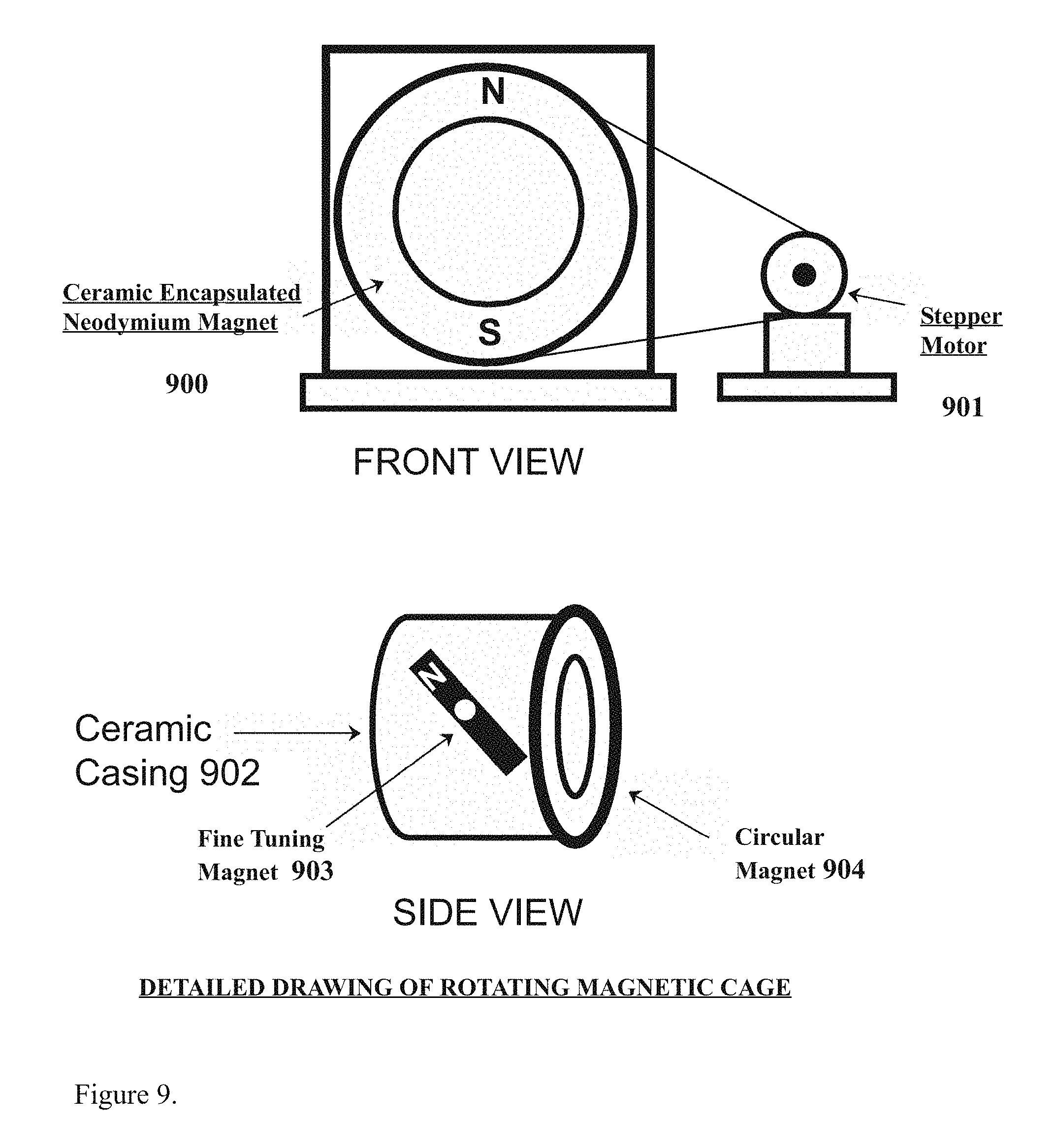
[0017] FIG. 9 depicts the a detailed drawing of the rotating magnetic cage as might be found in the preferred embodiment of the present invention for example.
[0018] FIG. 10 depicts the an alternate approach to the magnetics configuration for various elements as might be found in the preferred embodiment of the present invention for example.
A DETAILED DESCRIPTION OF THE DRAWINGS
[0019] FIG. 1 depicts the an idealized solution (100) representing a 1:1 ratio of electrolyte in an ionic solution solute which is totally disassociated in that the positive ions (101) are spherical and not polarized by the surrounding electric field. The solvation of ions is ignored except that the solvent plays no role except as the dialectric constant (relative permittivity), between the negatively charged electrons (102) and the balanced molecules of oxygen (103) and the balanced molecules of hydrogen (104) as depicted in the drawing.
[0020] FIG. 2 depicts the first solvation shell of the sodium ion (201) as might be found in brine water, surrounded by the oxygen molecules (202) and their complementing charged particles (203) and (204) for example as might be found in the preferred embodiment of the present invention prior to any interaction with the magnets or their magnetic fields.
[0021] FIG. 3 depicts e various properties (300) of the gaseous state (301) and the plasma state (302) which constitute the variations between the third and fourth forms of matter as known in physics for example as might be found in the preferred embodiment of the present invention.
[0022] FIG. 4 depicts the common forms of plasma as found in nature (400), the terrestrial created plasmas found in nature (401) and the astrophysical plasma states found in space (402), for example as might be found in the preferred embodiment of the present invention for example.
[0023] FIG. 5 depicts the end to end system components as might be found in the preferred embodiment of the present invention for example, comprising the Anode part (501), the Cathode part (502), the positive power supply (503), the negative power supply (504), the recirculation pump and filter (505), the pulse modulated power supply (506), the shrowded feed assembly (507) comprising the carbon rods, the tungsten rods, and the titanium rods (508), further comprising the aqueous water level (509) in the vessel which Is as an electrical shunt plasma arc gap (510) between the shroud and the described staggered metal perforated nickel plates (511) further comprising the hydrogen gas release chamber (512), and the hydrogen vacuum pump (513).
[0024] FIG. 6 depicts a detailed view of the ceramic shroud (600) for example as might be found in the preferred embodiment of the present invention, further comprising the copper sleeve (601), containing the replacement tips (602), which are designed to replace the main tip (603) on a periodic basis as for this example.
[0025] FIG. 7 depicts the nickel plate assembly from both the side view and back inside view for example as might be found in the preferred embodiment of the present invention for example, further comprising the Cathode part (701) comprised of a filament part of solid nickel wire or nickel plate (704), and an Anode part (702) comprising two solid metal perforated nickel plates (703), for example, on either side of the Cathode part, protected from the Cathode part by a glass or ceramic insulator (705) the glass insulator part being supported by a ceramic or glass support part (706) and thereby comprising the entire arc flashpoint design which is the subject of the present invention.
[0026] FIG. 8 depicts the various components of the three phase power supply parts (801) and (805) and (806) as might be found in the preferred embodiment of the present invention for example, comprising the said neutral leg (801) of the pulse modulated low voltage power supply, the anode leg (802) of the pulse modulated low voltage power supply part, the cathode side of the high voltage power supply (803), and the anode side of the high voltage power supply (804).
[0027] FIG. 9 depicts detailed drawing of the rotating magnetic cage as might be found in the preferred embodiment of the present invention for example, comprising the encapsulated neodymium magnet (900), the attached stepper motor (901) further depicting a side view of the assembly comprising the ceramic casing (902) further comprising the fine tuning magnet (903), and the circular neodymium magnet (904), for example.
[0028] FIG. 10 depicts the alternate neodymium magnet approach within the sealed housing (1000), comprising the two adjustable neodymium vertical magnets (1001), and the support bracket for the entire assembly (1002) as shown for example.
* * * * *
D00000
D00001
D00002
D00003
D00004
D00005
D00006
D00007
D00008
D00009
D00010
XML
uspto.report is an independent third-party trademark research tool that is not affiliated, endorsed, or sponsored by the United States Patent and Trademark Office (USPTO) or any other governmental organization. The information provided by uspto.report is based on publicly available data at the time of writing and is intended for informational purposes only.
While we strive to provide accurate and up-to-date information, we do not guarantee the accuracy, completeness, reliability, or suitability of the information displayed on this site. The use of this site is at your own risk. Any reliance you place on such information is therefore strictly at your own risk.
All official trademark data, including owner information, should be verified by visiting the official USPTO website at www.uspto.gov. This site is not intended to replace professional legal advice and should not be used as a substitute for consulting with a legal professional who is knowledgeable about trademark law.