Method For Manufacturing Metal Bottle, And Metal Bottle
AIHARA; Takeshi ; et al.
U.S. patent application number 16/471711 was filed with the patent office on 2019-10-31 for method for manufacturing metal bottle, and metal bottle. This patent application is currently assigned to TOYO SEIKAN CO., LTD.. The applicant listed for this patent is TOYO SEIKAN CO., LTD.. Invention is credited to Takeshi AIHARA, Toshiyuki HASEGAWA, Naoya MATSUMOTO, Takeshi MURASE, Tomohiko NAKAMURA, Nobuhiro SASAJIMA, Masaomi TAMURA.
| Application Number | 20190329925 16/471711 |
| Document ID | / |
| Family ID | 62627440 |
| Filed Date | 2019-10-31 |


| United States Patent Application | 20190329925 |
| Kind Code | A1 |
| AIHARA; Takeshi ; et al. | October 31, 2019 |
METHOD FOR MANUFACTURING METAL BOTTLE, AND METAL BOTTLE
Abstract
A method for manufacturing a metal bottle having a mouthpiece in an upper part of a bottomed cylindrical bottle body, including forming a screw part on the mouthpiece and then forming a curl at a tip of the mouthpiece. During formation of the screw part, a height of the first-stage screw thread from a tip side in a complete screw part and a height of the second-stage screw thread from the tip side are substantially equal and a distance between an apex part of the first-stage screw thread and a bottle axis is smaller than a distance between the apex part of the second-stage screw thread and the bottle axis. After formation of the curl, a distance between the apex part of the first-stage screw thread and the bottle axis and a distance between the apex part of the second-stage screw thread and the bottle axis are substantially equal.
| Inventors: | AIHARA; Takeshi; (Yokohama, JP) ; TAMURA; Masaomi; (Tokyo, JP) ; HASEGAWA; Toshiyuki; (Kawasaki, JP) ; MURASE; Takeshi; (Kawasaki, JP) ; NAKAMURA; Tomohiko; (Yokohama, JP) ; MATSUMOTO; Naoya; (Kawasaki, JP) ; SASAJIMA; Nobuhiro; (Yokohama, JP) | ||||||||||
| Applicant: |
|
||||||||||
|---|---|---|---|---|---|---|---|---|---|---|---|
| Assignee: | TOYO SEIKAN CO., LTD. Tokyo JP |
||||||||||
| Family ID: | 62627440 | ||||||||||
| Appl. No.: | 16/471711 | ||||||||||
| Filed: | October 10, 2017 | ||||||||||
| PCT Filed: | October 10, 2017 | ||||||||||
| PCT NO: | PCT/JP2017/036637 | ||||||||||
| 371 Date: | June 20, 2019 |
| Current U.S. Class: | 1/1 |
| Current CPC Class: | B65D 1/02 20130101; B65D 41/04 20130101; B21D 51/38 20130101; B65D 1/0246 20130101 |
| International Class: | B65D 1/02 20060101 B65D001/02; B65D 41/04 20060101 B65D041/04; B21D 51/38 20060101 B21D051/38 |
Foreign Application Data
| Date | Code | Application Number |
|---|---|---|
| Dec 22, 2016 | JP | 2016-249240 |
Claims
1. A method for manufacturing a metal bottle having a mouthpiece part in an upper part of a bottomed cylindrical bottle body, the method comprising the steps of: forming a screw part on the mouthpiece part and, after formation of the screw part, forming a curl part at a tip of the mouthpiece part, wherein, during the formation of the screw part, a height of the first-stage screw thread from a tip side in a complete screw part and a height of the second-stage screw thread from the tip side are substantially equal and a distance between an apex part of the first-stage screw thread and a bottle axis is formed smaller than a distance between an apex part of the second-stage screw thread and the bottle axis and, after the formation of the curl part, a distance between the apex part of the first-stage screw thread and the bottle axis and a distance between the apex part of the second-stage screw thread and the bottle axis are formed substantially equal.
2. The method for manufacturing the metal bottle according to claim 1, wherein, after the formation of the curl part, the height of the first-stage screw thread in the complete screw part is larger than the height of the second-stage screw head.
3. A metal bottle, comprising a mouthpiece part in an upper part of a bottomed cylindrical bottle body; a screw part in the mouthpiece part, and including a curl part at a tip of the mouthpiece part, wherein a height of a first-stage screw thread from a tip side in a complete screw part is larger than a height of a second-stage screw thread from the tip side, and a distance between an apex part of the first-stage screw thread and a bottle axis and a distance between an apex part of the second-stage screw thread and the bottle axis are substantially equal.
Description
TECHNICAL FIELD
[0001] The present invention relates to a method for manufacturing a metal bottle including a screw part and a metal bottle.
BACKGROUND ART
[0002] As a metal bottle, a metal bottle having a mouthpiece part, to which a screw-type metal cap is screwed, in an upper part of a bottomed cylindrical bottle body has been spread as a container with a cap for beverage products and the like. In such a metal bottle, the bottle body is subjected to drawing, drawing-ironing, or the like to be formed into a bottomed cylindrical shape, the diameter of an end of the upper part of the bottomed cylindrical-shaped bottle is reduced, so as to form a mouthpiece part, and a screw part is formed on the mouthpiece part by a screw molding device.
[0003] The screw molding device used in this case forms a screw part including a crest part and a trough part in the outer circumference of the mouthpiece part with an inner piece that is to be in contact with the inner circumferential surface of the mouthpiece part and an outer piece that is to be in contact with the outer circumferential surface of the mouthpiece part. Such a metal bottle has, at the tip of the mouthpiece part, a curl part, which is formed by folding back the tip thereof to the outer side by a curl molding device.
[0004] In such a conventional metal bottle, post machining for forming the curl part and the like is performed after formation of the screw part on the mouthpiece part. Thus, the apex part of the first-stage screw thread close to the curl part is problematically deformed to project further to the outer side than the apex part of other screw threads after post-machining because of an axial direction compression load due to the post machining and smooth opening and closing of the cap become hard, which causes a problem. Some measures for avoiding this problem have been proposed. For example, a conventional technique of PTL 1 described below, the height of the first-stage screw thread (a screw thread close to a curl part) of a screw part is formed lower than the height of screw threads of other stages in a predetermined angle range and, after formation of the curl part at the tip of a mouthpiece part, the height of the first-stage screw thread and the height of the screw threads of the other stages of the screw part are made substantially equal.
CITATION LIST
Patent Literature
[0005] [PTL 1] Japanese Patent Application Laid-open No. 2008-87071
SUMMARY OF INVENTION
Technical Problem
[0006] According to the conventional technique explained above, the height of the first-stage screw thread is once formed low when the screw part of the metal bottle is formed, and the height of the first-stage screw thread and the height of the screw threads of the other stages of the screw part are then made to be substantially equal by deformation in molding the curl part in the post machining.
[0007] After filling content in such a metal bottle, the mouthpiece part of the metal bottle is covered with a metal cap (a cup-shaped cap before screw machining), and the cap is machined into a shape corresponding to the shape of the screw part of the mouthpiece part by a screw machining roll, then the cap is fixed to the screw part and the bottle is sealed.
[0008] In this way, the cap is fixed in the shape corresponding to the shape of the screw part of the mouthpiece part of the metal bottle. However, as a container with a cap, it is further desired to improve sealing performance (a retaining force) of the cap by the screw part in the case of a high internal pressure, such as cases during retort sterilization of content or during carbonated beverage filling, easiness of capping machining, operability of recapping, and dropping impact resistance while keeping smoothness in opening and closing the screw-type cap.
[0009] The present invention has been proposed to solve such a problem. That is, a problem of the present invention is, for example, to provide a method for manufacturing a metal bottle having a screw part on a mouthpiece part, the method enabling, while keeping smoothness of opening and closing a screw cap, easily manufacturing of a metal bottle in which sealing a cap by the screw part is surely performed even when an internal pressure of the bottle increases, and improvement of easiness of capping machining and operability of recapping, improvement of dropping impact resistance, and the like. Another problem of the present invention is to provide a metal bottle that exerts practically advantageous effects explained above.
Solution to Problem
[0010] In order to solve such a problem, the present invention includes the following configuration.
[0011] A method for manufacturing a metal bottle having a mouthpiece part in an upper part of a bottomed cylindrical bottle body, the method including the steps of: forming a screw part on the mouthpiece part and, after formation of the screw part, forming a curl part at a tip of the mouthpiece part, wherein, during the formation of the screw part, a height of the first-stage screw thread from a tip side in a complete screw part and a height of the second-stage screw thread from the tip side are substantially equal and a distance between an apex part of the first-stage screw thread and a bottle axis is formed smaller than a distance between an apex part of the second-stage screw thread and the bottle axis and, after the formation of the curl part, a distance between the apex part of the first-stage screw thread and the bottle axis and a distance between the apex part of the second-stage screw thread and the bottle axis are formed substantially equal.
[0012] A metal bottle, comprising a mouthpiece part in an upper part of a bottomed cylindrical bottle body; a screw part in the mouthpiece part, and including a curl part at a tip of the mouthpiece part, wherein a height of a first-stage screw thread from a tip side in a complete screw part is larger than a height of a second-stage screw thread from the tip side, and a distance between an apex part of the first-stage screw thread and a bottle axis and a distance between an apex part of the second-stage screw thread and the bottle axis are substantially equal.
Advantageous Effects of Invention
[0013] With the method for manufacturing a metal bottle of the present invention, the method enables easily manufacturing of a metal bottle in which sealing a cap by the screw part is surely performed even when an internal pressure of the bottle increases, and improvement of easiness of capping machining and operability of recapping, improvement of dropping impact resistance, and the like while keeping smoothness of opening and closing a screw cap.
[0014] With the metal bottle of the present invention, a metal bottle that exerts practically advantageous effects explained above can be provided.
BRIEF DESCRIPTION OF DRAWINGS
[0015] FIG. 1 is an explanatory diagram showing an overall configuration of a metal bottle according to an embodiment of the present invention.
[0016] FIG. 2 is an explanatory diagram (a partial sectional view) showing a state in which a screw part is formed in a mouthpiece part of the metal bottle according to the embodiment of the present invention.
[0017] FIG. 3 is an explanatory diagram (a partial sectional view) showing a state where the screw part is formed in the mouthpiece part of the metal bottle, followed by forming a curl part according to the embodiment of the present invention.
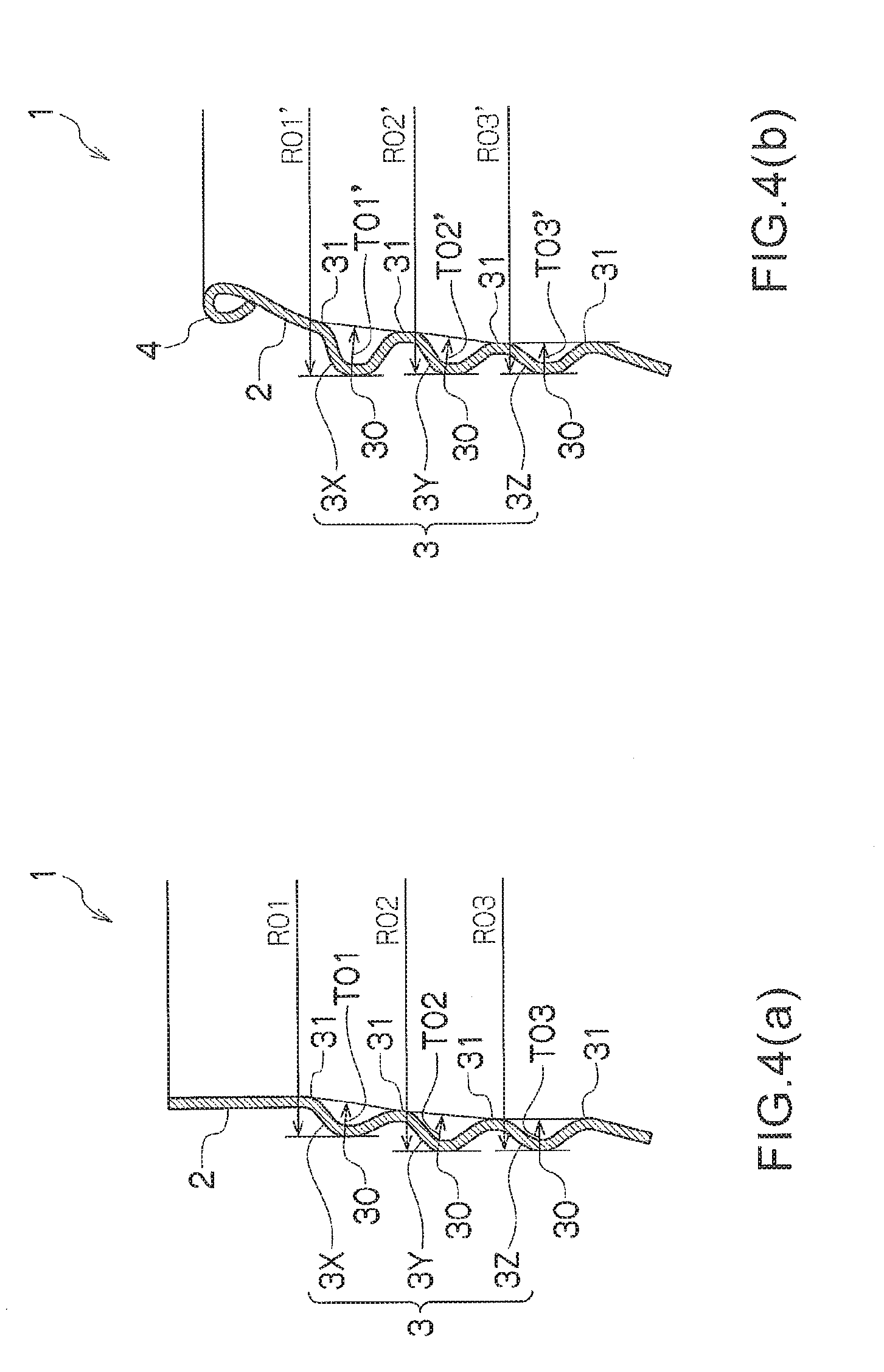
[0018] FIG. 4 is an explanatory diagram showing another embodiment of the present invention (FIG. 4 (a) shows a state where a screw part is formed on a mouthpiece part but a curl part is not formed yet and FIG. 4 (b) shows a state where the screw part is formed on a mouthpiece part, followed by forming a curl part).
DESCRIPTION OF EMBODIMENTS
[0019] Embodiments of the present invention are explained below with reference to the drawings. In the following explanation, the same reference numerals and signs indicate parts having the same functions even when they are used for designating parts in different figures. Redundant explanation of the parts in the figures is omitted as appropriate.
[0020] As shown in FIG. 1, a metal bottle 1 includes a mouthpiece part 2 coaxial with a bottle axis O in an upper part of a bottle body 1A. In the mouthpiece part 2, a screw part 3 is formed. A curl part 4 is formed at the tip of the mouthpiece part 2. For forming the screw part 3 and the curl part 4 in the mouthpiece part 2, as explained above, a screw molding device and a curl molding device are used.
[0021] The screw molding device is configured to bring an inner piece into contact with the inner circumferential surface of the mouthpiece part 2 and to bring an outer piece into contact with the outer circumferential surface of the mouthpiece part 2, so as to form the screw part 3 in the outer circumference of the mouthpiece part 2. The curl molding device forms the screw part 3 on the mouthpiece part 2, and thereafter, presses a curl-shaped mold against the tip of the mouthpiece part 2 and fold's back the tip of the mouthpiece part 2 to the outer side, so as to form the curl part 4.
[0022] A cap 5 is fixed to the mouthpiece part 2 of the metal bottle 1. The cap 5 includes, for example, in a lower part of a cap body 5A, a score part 5B, a bridge part 5C, and a ring part 5D. The cap 5 is fixed after filling the content in the metal bottle 1. The cap 5 is a metal cap made of a metal plate of aluminum or the like in which screw machining is applied to the cap body 5A by a capping device (not shown) along the screw part 3 provided on the mouthpiece part 2 and the ring part 5D is caulked on a lower side of the screw part 3.
[0023] FIG. 2 shows a formed state of the screw part 3 on the mouthpiece part 2 of the metal bottle 1. In a cross section shown in the figure of the screw part 3, at least the first-stage screw thread 3A and the second-stage screw thread 3B from the tip side are formed. The first-stage screw thread 3A and the second-stage screw thread 3B each include apex parts 30 projecting toward the outer side and bottom parts 31 projecting toward the inner side.
[0024] The mouthpiece part 2 of the metal bottle 1 is formed such that the height T1 of the first-stage screw thread 3A and the height T2 of the second-stage screw thread 3B in the complete screw part of the screw part 3 explained below be substantially equal and the distance R1 between the apex part 30 of the first-stage screw thread 3A and the bottle axis O be smaller than the distance R2 between the apex part 30 of the second-stage screw thread 3B and the bottle axis O (R1<R2).
[0025] Now, the "height of a screw thread" is defined as a maximum value of the distance between a line L joining the bottom parts 31 and the apex parts 30 in the screw part 3 (the screw threads 3A and 3B). In the screw part 3, a screw thread gradually increases in height from a screw start point and reaches substantially constant height of the screw thread. A range in which the screw thread gradually increases in height from the screw start point is defined as an incomplete screw part. A range having a substantially constant height of the screw thread is defined as a complete screw part. In FIG. 2, the height of the first-stage screw thread 3A of the screw part 3 is the distance T1 between the apex part 30 and the straight line L and the height of the second-stage screw thread 3B of the screw part 3 is the distance T2 between the apex part 30 and the straight line L. In the embodiment of the present invention, the distance T1 and the distance T2 are formed to be substantially equal (including just equal) (T1.apprxeq.T2 and T1=T2).
[0026] FIG. 3 shows a formed state of the curl part 4 in the mouthpiece part 2 of the metal bottle 1. As explained above, the curl part 4 is formed after the formation of the screw part 3. Therefore, after curling-machining of the curl part 4, the screw part 3, in particular, the first-stage screw thread 3A is deformed to project toward the outer side. The screw part 3 are formed, after the formation of the curl part 4, such that the distance R1' between the apex part 30 of the first-stage screw thread 3A of the screw part 3 and the bottle axis O and the distance R2' between the apex part 30 of the second-stage screw thread 3B of the screw part 3 and the bottle axis O be substantially equal (including just equal) (R1'.apprxeq.R2' and R1'=R2').
[0027] According to the embodiment of the present invention with such a configuration, the screw part 3 are formed, in a state after the formation of the screw part 3 and before the formation of the curl part 4, such that the distance R1 between the apex part 30 of the first-stage screw thread 3A of the screw part 3 and the bottle axis O be smaller than the distance R2 between the apex part 30 of the second-stage screw thread 3B of the screw part 3 and the bottle axis O (R1<R2). Therefore, even when the first-stage screw thread 3A of the screw part 3 is deformed so that the diameter of the first-stage screw thread 3A be expanded during the formation of the curl part 4, the apex part 30 of the screw thread 3A is prevented from projecting further to the outer side than the apex part 30 of the screw thread 3B. Consequently, smooth opening and closing of the cap 5 can be achieved.
[0028] In the state where the screw part 3 is formed but the curl part 4 is not formed yet, the screw part 3 are formed such that the height (the distance T1) of the first-stage screw thread 3A and the height (the distance T2) of the second-stage screw thread 3B of the screw part 3 be substantially equal (including just equal) (T1.apprxeq.T2 and T1=T2). Therefore, after the formation of the curl part 4, since the first-stage screw thread 3A is deformed such that the diameter of the first-stage screw thread 3A be expanded, the screw part 3 is formed so that the height (the distance T1') of the first-stage screw thread 3A be larger than the height (the distance T2') of the second-stage screw thread 3B (T1'>T2'). Consequently, in a state in which the cap 5 is fixed, the height (the distance T1') of the first-stage screw thread 3A can be set sufficiently large. Even when a bottle internal pressure is high, sufficiently sealabilty of the cap 5 by the screw part 3 can be secured.
[0029] By making the height of the first-stage screw thread 3A of the screw part 3 relatively large, a screw trough can be made deeper. Therefore, during the capping machining, a machining roller of the capping device easily enters the screw trough, so as to facilitates capping machining.
[0030] Further, by making the height of the first-stage screw thread 3A of the screw part 3 relatively large, when the cap 5 is recapped, the cap 5 can easily engage with a screw thread, to thereby facilitate smooth recapping.
[0031] As shown in FIG. 3, in the metal bottle 1 according to the embodiment of the present invention, the line L joining the bottom parts 31 of the screw part 3 is inclined to the center side with respect to the bottle axis O as the line L goes toward an upper part of the metal bottle 1. Consequently, axial load strength of the entire metal bottle 1 increases and the metal bottle 1 is less easily deformed. Thus, impact resistance upon drop of the screw part 3 formed in the mouthpiece part 2 can be enhanced.
[0032] In the embodiment explained above, an example is explained in which the screw part 3 includes the first-stage screw thread 3A and the second-stage screw thread 3B. However, as shown in FIG. 4, the screw part 3 in the present invention may include screw parts (screw threads) in third or higher stages.
[0033] FIG. 4 shows an example in which the screw part 3 includes a first-stage screw thread 3X, a second-stage screw thread 3Y, and a third-stage screw thread 3Z. In this example, before curling machining shown in FIG. 4(a), a relation among heights T01, T02, and T03 of the screw threads 3X, 3Y, and 3Z in the three stages satisfies the followings: (T01.apprxeq.T02.apprxeq.T03, T01=T02=T03). A relation among distances R01, R02, and R03 between apex parts 30 of the screw threads 3X, 3Y, and 3Z and the bottle axis O satisfies the followings: (R01<R02.apprxeq.R03, R01<R02=R03).
[0034] After curling machining for forming the curl part 4 shown in FIG. 4(b), a relation among heights T01', T02', and T03' of the screw threads 3X, 3Y, and 3Z in the three stages satisfies the followings: (T01'>T02'=T03', T01'>T02'=T03') and a relation among distances R01', R02', and R03' between apex parts 30 of the screw threads 3X, 3Y, and 3Z and the bottle axis O satisfies the followings: (R01'=R02' R03', R01'=R02'=R03').
[0035] As explained above, according to the method for manufacturing a metal bottle of the present invention, the method enables easily manufacturing of a metal bottle in which sealing a cap by the screw part is surely performed even when an internal pressure of the bottle increases, and improvement of easiness of capping machining and operability of recapping, improvement of dropping impact resistance, and the like while keeping smoothness of opening and closing a screw cap. It is possible to obtain the metal bottle that assumes the practically advantageous effects explained above.
REFERENCE SIGNS LIST
[0036] 1 Metal bottle [0037] 1A Bottle body [0038] 2 Mouthpiece part [0039] 3 Screw part [0040] 4 Curl part [0041] 5 Cap [0042] 5A Cap body [0043] 5B Score part [0044] 5C Bridge part [0045] 5D Ring part, [0046] 30 Apex part [0047] 31 Bottom part
* * * * *
D00000
D00001
D00002
D00003
D00004
XML
uspto.report is an independent third-party trademark research tool that is not affiliated, endorsed, or sponsored by the United States Patent and Trademark Office (USPTO) or any other governmental organization. The information provided by uspto.report is based on publicly available data at the time of writing and is intended for informational purposes only.
While we strive to provide accurate and up-to-date information, we do not guarantee the accuracy, completeness, reliability, or suitability of the information displayed on this site. The use of this site is at your own risk. Any reliance you place on such information is therefore strictly at your own risk.
All official trademark data, including owner information, should be verified by visiting the official USPTO website at www.uspto.gov. This site is not intended to replace professional legal advice and should not be used as a substitute for consulting with a legal professional who is knowledgeable about trademark law.