Suspension group for motor vehicle, wheel group for motor vehicle, front end of a motor vehicle and motor vehicle thereof
RAFFAELLI; Andrea
U.S. patent application number 16/465163 was filed with the patent office on 2019-10-31 for suspension group for motor vehicle, wheel group for motor vehicle, front end of a motor vehicle and motor vehicle thereof. The applicant listed for this patent is PIAGGIO & C. S.P.A.. Invention is credited to Andrea RAFFAELLI.
| Application Number | 20190329616 16/465163 |
| Document ID | / |
| Family ID | 58455472 |
| Filed Date | 2019-10-31 |


View All Diagrams
| United States Patent Application | 20190329616 |
| Kind Code | A1 |
| RAFFAELLI; Andrea | October 31, 2019 |
Suspension group for motor vehicle, wheel group for motor vehicle, front end of a motor vehicle and motor vehicle thereof
Abstract
A suspension group for a motor vehicle, wherein said suspension group includes: a wheel guide, which extends along a longitudinal axis, which includes a wheel attachment for connection to a rotation pin of a wheel having a rotation axis orthogonal to said longitudinal axis, wherein the wheel guide extends between a first end and a second end, opposite the first end, a support arm functionally connected to the wheel guide respectively by means of: a first crank rotatably connected at said second end to the wheel guide and to the support arm; a second crank rotatably connected at said first end to the wheel guide and to the support arm, wherein the wheel guide elements, the support arm and the first and second crank define a suspension quadrilateral, wherein, between at least two of said elements chosen between the wheel guide, the support arm, the first and the second crank, a shock absorber group is interconnected in such a way that the shock absorber group varies its extension as the movement of the suspension quadrilateral varies.
| Inventors: | RAFFAELLI; Andrea; (Pontedera, PISA, IT) | ||||||||||
| Applicant: |
|
||||||||||
|---|---|---|---|---|---|---|---|---|---|---|---|
| Family ID: | 58455472 | ||||||||||
| Appl. No.: | 16/465163 | ||||||||||
| Filed: | December 7, 2017 | ||||||||||
| PCT Filed: | December 7, 2017 | ||||||||||
| PCT NO: | PCT/IB2017/057729 | ||||||||||
| 371 Date: | May 30, 2019 |
| Current U.S. Class: | 1/1 |
| Current CPC Class: | B60G 2300/45 20130101; B60G 2300/122 20130101; B60G 13/005 20130101; B62K 5/00 20130101; B62K 5/08 20130101; B62K 2005/001 20130101; B60G 3/04 20130101; B60G 7/001 20130101; B60G 2204/30 20130101; B62K 25/00 20130101; B62K 5/027 20130101; B60G 3/01 20130101; B62K 5/10 20130101; B60G 3/20 20130101 |
| International Class: | B60G 3/04 20060101 B60G003/04; B60G 13/00 20060101 B60G013/00; B60G 7/00 20060101 B60G007/00; B62K 5/027 20060101 B62K005/027; B62K 5/00 20060101 B62K005/00 |
Foreign Application Data
| Date | Code | Application Number |
|---|---|---|
| Dec 7, 2016 | IT | 102016000124367 |
Claims
1. A suspension group (10) for a motor vehicle (100), wherein said suspension group (10) comprises: a wheel guide (1), which extends along a longitudinal axis (T-T), which comprises a wheel attachment (2) for connection to a rotation pin (3) of a wheel (102,102a) having a rotation axis (R-R) orthogonal to said longitudinal axis (T-T), wherein the wheel guide (1) extends between a first end (1a) and a second end (1b), opposite the first end (1a), a support arm (8) functionally connected to the wheel guide (1) respectively by means of: a first crank (9) pivotally connected at said second end (1b) to the wheel guide (1) and to the support arm (8); a second crank (12) pivotally connected at said first end (1a) to the wheel guide (1) and to the support arm (8), wherein the wheel guide elements (1), the support arm (8) and the first (9) and second (12) crank define a suspension quadrilateral, wherein, between at least two of said elements chosen between the wheel guide (1), the support arm (8), the first and the second crank (9,12), a shock absorber group (7) is interconnected in such a way that the shock absorber group (7) varies its extension when the movement of the suspension quadrilateral varies.
2. A suspension group (10) for a motor vehicle (100) according to claim 1, wherein the shock absorber group (7) is provided between said first crank (9) and said second crank (12).
3. A suspension group (10) for a motor vehicle (100) according to claim 1, wherein the shock absorber group (7) is provided between said first crank (9) and said support arm (8).
4. A suspension group (10) for a motor vehicle (100) according to claim 1, wherein the shock absorber group (7) is provided between said first crank (9) and said wheel guide (1).
5. A suspension group (10) for a motor vehicle (100) according to claim 1, wherein the shock absorber group (7) is provided between said second crank (12) and said support arm (8).
6. A suspension group (10) for a motor vehicle (100) according to claim 1, wherein the shock absorber group (7) is provided between said second crank (12) and said wheel guide (1).
7. A suspension group (10) for a motor vehicle (100) according to claim 1, wherein the shock absorber group (7) is provided between said support arm (8) and said wheel guide (1).
8. A suspension group (10) for a motor vehicle (100) according to any one of the previous claims, wherein the shock absorber group (7) comprises a base portion (7a) and a head portion (7b), opposite the base portion (7a), said base (7a) and head (7b) portions being connected to said two elements by means of respective joints.
9. A suspension group (10) for a motor vehicle (100) according to any one of the preceding claims, wherein said shock absorber group comprises resilient means (72) and a damper (71).
10. A suspension group (10) for a motor vehicle (100) according to any one of the preceding claims, wherein said shock absorber group (7) is shaped so as to compress as the load on the wheel (102,102a) increases.
11. A suspension group (10) for a motor vehicle (100) according to any one of the claims 1 to 9, wherein said shock absorber group (7) is shaped so as to extend as the load on the wheel (102,102a) increases.
12. A suspension group (10) for a motor vehicle (100) according to any one of the preceding claims, wherein the first crank (9) is rotatably connected at said second end (1b), by means of a first hinge (9a) arranged on the wheel guide (1), and a second hinge (9b) arranged on the support arm (8), and wherein the second crank (12) is pivotally connected at said first end (1b), by means of a third hinge (12a) disposed on the support arm (8), and by means of a fourth hinge (12b) disposed on the wheel guide (1),
13. A suspension group (10) for a motor vehicle (100) according to any one of the preceding claims, wherein the suspension quadrilateral is contained within a volume (180) delimited by a rim (184) of said wheel (102,102a), and wherein the shock absorber group (7) is arranged at least partially outside said volume (180).
14. A suspension group (10) for a motor vehicle (100) according to claim 13, wherein the shock absorber group (7) is disposed completely outwardly or cantilevered with respect to the volume (180) of said rim (184).
15. A suspension group (10) for a motor vehicle (100) according to claim 12, wherein the shock absorber group (7) comprises only one damper (71), and the first and second hinges (9a, 9b) of the first crank (9) are rigid or interlocking in such a way that the first crank (9) acts as a torsion bar carrying out the function of said resilient means (72).
16. A suspension group (10) for a motor vehicle (100) according to claim 12, wherein the third and fourth hinges (12a, 12b) of the second crank (12) are rigid or interlocking so that the second crank (12) acts as a torsion bar carrying out the function of said resilient means (72).
17. A suspension group (10) according to any one of the preceding claims, wherein the second crank (12) has a dimensional relationship with respect to said first crank (9) that defines a quadrilateral suspension configuration such that the instantaneous center of rotation converges substantially to infinity.
18. A suspension group (10) according to any one of the preceding claims, wherein the second crank (12) has a dimensional relationship with respect to said first crank (9) that defines a quadrilateral suspension configuration such that the instantaneous center of rotation converges in a finite point from the side of said support arm (8).
19. A suspension group (10) for a motor vehicle (100) according to any one of the preceding claims, wherein the wheel guide (1) comprises a tubular jacket (4) which defines a housing space (5), wherein the shock absorber group (7) is housed at least partially in said housing space (5).
20. A wheel group (102,102a) of a motor vehicle (100) comprising a suspension group (10) according to one or more of the preceding claims.
21. A front end (108) of a motor vehicle (100) that comprises: a front end chassis (116), a pair of front wheels (102,102a) kinematically connected to the front end chassis (116) by means of a rolling articulated quadrilateral (120), wherein said front end (108) comprises, at each front wheel (102,102a), a suspension group (10) according to any one of claims 1 to 19 and/or a wheel group according to claim 20.
22. A motor vehicle (100) comprising a drive wheel (103) at the rear axle (109), a wheel group (102,102a) according to claim 20, and/or a front end according to claim 21.
Description
SCOPE OF THE INVENTION
[0001] The present invention relates to a suspension group of a wheel of a motor vehicle, for example a two- or three-wheel motor vehicle.
[0002] Moreover, the present invention relates to a wheel group of a motor vehicle which integrates said suspension group, both in a motor vehicle front end and in a motor vehicle thereof.
PRIOR ART
[0003] Various suspension solutions applied to the wheel of a motor vehicle are known. The suspensions must guarantee a predetermined stiffness to the wheel support and, at the same time, provide reduced dimensions and weight to improve the dynamic behavior of the vehicle, particularly in three-wheeled motor vehicles. The latter comprise a drive wheel at the rear and two wheels at the front of the steering and tilting type. The rear wheel has the purpose of providing the drive torque, while the front wheels--substantially parallel to each other--provide the directionality of the vehicle.
[0004] The front wheels are kinematically connected to each other by means of kinematic systems which ensure that the same will roll and/or steer synchronously and symmetrically, for example, via the interposition of articulated quadrilaterals.
[0005] A suspension group with a quadrilateral structure is known in the name of the same applicant which comprises a wheel guide equipped with a shock absorber group integrated inside a jacket. The wheel guide is in turn connected to a support arm by means of: a crank, hinged at respective ends of the wheel guide and of the support arm, and a guide rod, keyed to a head of the shock absorber group slidably coupled inside the jacket. The travel of the guide rod is defined by a slot made on the jacket. The head of the shock absorber group forms a cylinder-piston coupling and acts as an axial guide for the sliding of the shock absorber group.
[0006] The aforementioned solution, while being functionally valid, has some drawbacks. The head portion is open towards the outside through the slot and, therefore, the cylinder-piston coupling is subject to the accumulation of dirt; this aspect may cause deterioration of the seal and of the functionality in general.
[0007] The need to solve the aforementioned disadvantage is therefore perceived.
[0008] The need to improve the performance of the suspension group is also perceived in terms of: better control of the trajectory of the wheel fixed to the wheel guide of the shock absorber, greater strength of the suspension group, and production cost.
SUMMARY OF THE INVENTION
[0009] It is therefore an object of the present invention to provide a motor vehicle suspension group which is improved in terms of dynamic response and production costs with respect to the solution according to the prior art.
[0010] It is another object of the present invention to provide a wheel group which comprises said suspension group which achieves the same purposes.
[0011] It is also an object of the present invention to provide a motor vehicle front end and a motor vehicle thereof which achieve the same purposes.
[0012] These and other objects are achieved by a suspension group for a motor vehicle according to claim 1.
DESCRIPTION OF THE DRAWINGS
[0013] The present invention will be illustrated hereinafter with the following description of an embodiment thereof, made by way of a non-limiting example, with reference to the accompanying drawings wherein:
[0014] FIGS. 1a-1b are schematic views of possible configurations of suspension groups in accordance with the present invention;
[0015] FIG. 2a shows a perspective view of a motor vehicle which comprises at the front end a pair of wheels provided with a suspension group, according to the present invention;
[0016] FIG. 2b shows an enlarged perspective view of the front end of the motor vehicle of FIG. 2a;
[0017] FIG. 3 is a sectional view of a suspension group, according to the present invention, applied to a corresponding wheel;
[0018] FIG. 3A is a detailed schematic view of FIG. 3;
[0019] FIG. 4 shows a perspective view of the suspension group, in a first extended configuration of the shock absorber group;
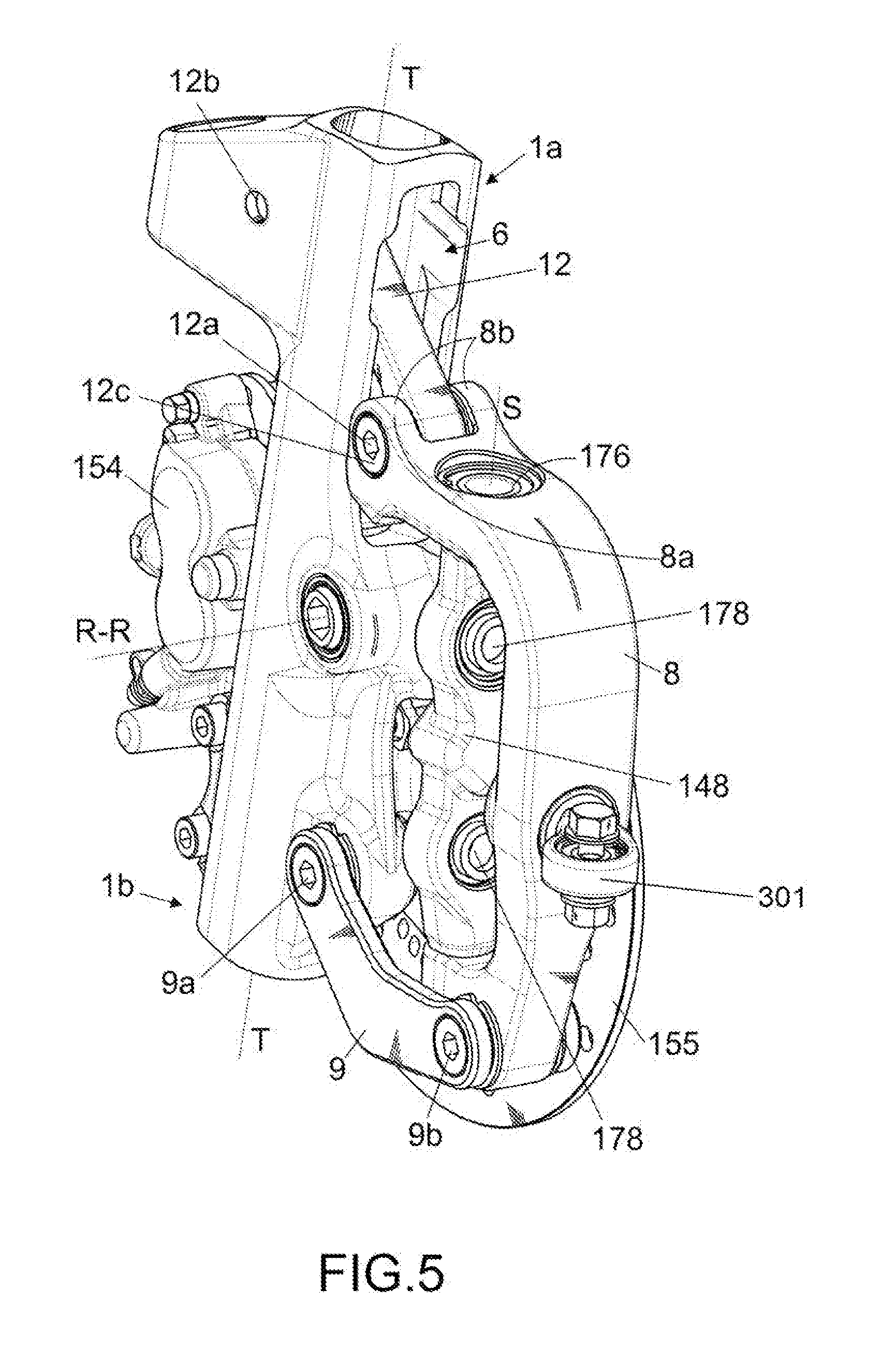
[0020] FIG. 5 shows a perspective view of the suspension group of FIG. 4, in a second compressed configuration of the shock absorber group;
[0021] FIGS. 6a-6b show views, respectively in an extended and compressed configuration, of a suspension group according to a further embodiment of the present invention;
[0022] FIG. 7 is a perspective view of the suspension group shown in FIGS. 6a and 6b;
[0023] FIGS. 8, 9, 10, 11 show views of further embodiments of a suspension group in accordance with the present invention;
[0024] FIG. 12 shows a partial perspective view of a motor vehicle comprising a front end according to a further embodiment of the present invention;
[0025] FIG. 13 shows a front view of a front wheel of the motorcycle of FIG. 12;
[0026] FIG. 14 shows sectional views of the wheel of FIG. 13;
[0027] FIG. 15 shows a partial perspective view of a motorcycle comprising a front end according to a further embodiment of the present invention;
[0028] FIG. 16 shows a front view of a front wheel of the motorcycle of FIG. 15;
[0029] FIG. 17 shows sectional views of the wheel of FIG. 16.
[0030] The elements or parts of elements in common between the embodiments described hereinafter will be indicated at the same numerical references.
DETAILED DESCRIPTION
[0031] With reference to the aforementioned figures, a total schematic view of a motor vehicle according to the present invention is collectively indicated at 100.
[0032] For the purposes of the present invention, the term "motor vehicle" is to be considered in the broad sense, comprising any motorcycle having at least three wheels, i.e., two front wheels 102,102a, as better described below, and at least one rear wheel 103. Thus, so-called quadricycles are also included in the definition of a motor vehicle, having two wheels on the front end and two wheels on the rear axle.
[0033] The motor vehicle 100 comprises a chassis 101 extending from a front end 108, supporting at least two front wheels 102, 102a, to a rear axle 109, supporting one or more rear wheels 103.
[0034] Even if not shown, a right front wheel 102, shown schematically in FIG. 2a, and a left front wheel 102a with respect to a driver on board the vehicle according to the direction of travel are identified. The wheels 102,102a are disposed to the left and to the right of a centerline plane M-M of the motor vehicle, relative to the observation point of a driver thereof.
[0035] For the purposes of the present invention, the chassis 101 of the motor vehicle may be of any shape and size and may, for example, be of the lattice-type, box-type, single- or double-cradle, and so on.
[0036] In particular, the front end 108 of the motor vehicle 100 comprises a front end frame 116 and a pair of front wheels 102, 102a, kinematically connected to the front end chassis 116 by a rolling articulated quadrilateral 120. Said rolling articulated quadrilateral 120 allows the front wheels 102, 102a to roll, that is to say, incline with respect to the perpendicular to the ground.
[0037] The front end 108 comprises, at each front wheel 102,102a, a suspension group 10.
[0038] As better shown in FIGS. 3 and 4, the suspension group 10 comprises a wheel guide 1, which extends along a longitudinal axis T-T. The wheel guide 1 provides a wheel attachment 2 for connection to a rotation pin 3 of a wheel 102,102a with a rotation axis R-R orthogonal to the longitudinal axis T-T.
[0039] In particular, the wheel guide 1 extends between a first end 1a and a second end 1b, opposite to each other.
[0040] The suspension group 10 further comprises a shock absorber group 7 which extends from a base portion 7a to a head portion 7b, opposite to the base portion 7a, said base and head portion being mutually movable and connected to at least two elements between the wheel guide 1, a support arm 8, a first crank 9 and a crank 12, better described hereinafter.
[0041] For example, said shock absorber group 7 comprises resilient means 72 and a damper 71.
[0042] The suspension group 10 comprises a support arm 8 functionally connected to the wheel guide 1 respectively by means of a first crank 9 and a second crank 12.
[0043] The first crank 9 is pivotally connected at said second end 1b to the wheel guide 1, for example by means of a first hinge 9a, and to the support arm 8, for example by means of a second hinge 9b.
[0044] The second crank 12 is pivotally connected at said first end 1a to the wheel guide 1 and to the support arm 8.
[0045] For example, the second crank 12 is pivotally connected at said first end 1a, by means of a third hinge 12a disposed on the support arm 8, and by means of a fourth hinge 12b disposed on the wheel guide 1,
[0046] According to one embodiment, the first crank 9 is pivotally connected at said second end 1b, by means of a first hinge 9a disposed on the wheel guide 1, and a second hinge 9b disposed on the support arm 8.
[0047] The wheel guide 1, the support arm 8 and the first 9 and second 12 crank define collectively an articulated suspension quadrilateral. Each wheel is pivotally connected to its own articulated suspension quadrilateral. The suspension quadrilaterals are connected to each other by means of the rolling articulated quadrilateral 120. The rolling articulated quadrilateral 120 then connects the suspension quadrilaterals to the chassis of the motor vehicle. Advantageously, between at least two of said elements chosen between the wheel guide 1, the support arm 8, the first crank 9 and the second crank 12, a shock absorber group 7 is interconnected in such a way that the shock absorber group 7 varies its extension when the movement of the suspension quadrilateral varies.
[0048] In general, such shock absorber group comprises resilient means 72, typically but not exclusively a coil spring or a torsion bar, and a damper 71. The resilient means 72 and the damper 71 are not necessarily disposed between the same two elements chosen between the wheel guide 1, the support arm 8, the first crank 9 and the second crank 12. Therefore, the resilient means 72 and the damper 71, if integrated together, connect the same elements of the suspension quadrilateral, while if disengaged, may connect the same elements of the quadrilateral or distinct pairs of elements of the suspension quadrilateral.
[0049] According to one embodiment, the shock absorber group is provided between said first crank 9 and said second crank 12.
[0050] According to one embodiment, the shock absorber group 7 is provided between said first crank 9 and said support arm 8.
[0051] According to one embodiment, the shock absorber group 7 is provided between said first crank 9 and said wheel guide 1.
[0052] According to one embodiment, the shock absorber group 7 is provided between said second crank 12 and said support arm 8.
[0053] According to one embodiment, the shock absorber group 7 is provided between said second crank 12 and said wheel guide 1.
[0054] According to one embodiment, the shock absorber group 7 is provided between said support arm 8 and said wheel guide 1.
[0055] According to one embodiment, the resilient means 72 are disposed so as to compress with the increasing load on the wheel 102,102a: this condition is illustrated schematically in FIG. 1a, wherein various possible inclinations/arrangements of resilient means 72 are illustrated which are compressed as described.
[0056] According to a further possible embodiment, the resilient means 72 are disposed so as to extend with the increasing load on the wheel 102,102a: this condition is illustrated schematically in FIG. 1b, wherein various possible inclinations/arrangements of resilient means 72 are illustrated which are extended as described.
[0057] According to one embodiment, the suspension quadrilateral 10 is contained within a volume 180 defined by a rim 184 of said wheel 102,102a, i.e. the empty space which, according to a radial direction, is found inside the rim 184. The shock absorber 7 may be arranged at least partially outside said volume 184, according to an axial direction. Preferably, the shock absorber 7, in this configuration, is at least partially cantilevered or disposed outwardly with respect to the volume 180.
[0058] For example, in such at least partially cantilevered configuration, the shock absorber is preferably doubly hinged to said first and second crank 9,12, so as to rotate with the latter. In other words, in this configuration the shock absorber has a floating anchor.
[0059] Preferably, the shock absorber 7 is disposed completely outwardly or cantilevered with respect to the volume 180, from an inner side of the wheel, facing towards said centerline plane M-M.
[0060] Due to this positioning of the shock absorber, it is possible to reduce the dimensions of the stub axle of the wheel, and therefore also the relative costs, since a smaller stub axle results in less material and less processing. This arrangement of the suspension group also allows the construction of a vehicle with a narrower track width.
[0061] Moreover, the shock absorber 7 has simplified couplings at the ends 7a,7b and its external positioning allows a greater margin of maneuverability for its size, since its hydraulic body and the spring do not constrain the dimensions of the passage inside the stub axle.
[0062] Moreover, due to the positioning outside of the volume 180, it is possible to obtain a behavior with a high geometric progressivity which allows springs with a single elastic coefficient to be used.
[0063] The resilient means 72 typically comprise coil springs with coils wound according to a constant or even variable pitch.
[0064] For example, the resilient means are springs disposed coaxially with the shock absorber 7, in a known manner.
[0065] The resilient means 72 may be mounted either in series or in parallel with respect to the shock absorber 7.
[0066] According to one embodiment, the resilient means 72 are disposed parallel to the shock absorber 7.
[0067] According to a possible further embodiment (FIGS. 12-17), the first and second hinges 9a,9b of the first crank 9 are rigid or interlocking so that the first crank 9 behaves as a torsion bar carrying out the function of said resilient means 72. Moreover, preferably, in this configuration the shock absorber 7 comprises only a damper 71.
[0068] It is also possible to provide for the third and fourth hinges 12a,12b of the second crank 12 being of a rigid or interlocking type so that the second crank 12 behaves as a torsion bar, providing the function of said resilient means. Moreover, preferably, in such configuration the shock absorber 7 comprises only a damper 71.
[0069] The use of said first and second cranks 9,12 acting as torsion bars may be either reciprocating or concurrent; in other words it is possible to provide a single torsion bar (as a first or second crank) or both cranks may act as torsion bars.
[0070] Due to the use of the torsion bars, it is possible to eliminate rotoidal torques, whether they are bearings or bushings, with a considerable advantage in terms of costs.
[0071] Furthermore, by eliminating the classic helical spring, especially if contained within the jacket 4, the overall dimensions are drastically improved because the size of the jacket itself may be reduced and/or the body of the shock absorber may be increased to improve the behavior of the hydraulic part (i.e. damping) of the suspension.
[0072] Moreover, since the torsion bar is screwed between the support arm 8 and the jacket 4 or in any case the head portion 7b of the shock absorber 7, the play of the ball bearings normally used to guide the rotation is not perceived.
[0073] As seen, according to a possible embodiment, the wheel guide 1 further comprises a tubular jacket 4, i.e. a portion of hollow tube, which defines a housing space 5, hereinafter space 5.
[0074] The tubular jacket 4, again as shown in the section of FIG. 3 or in FIG. 5, comprises, at the first end 1a, a slot 6, which extends for at least one section along the longitudinal axis T-T.
[0075] The jacket 4 is shaped to contain the shock absorber group 7 in the space 5 (FIG. 3). The shock absorber group 7 comprises a damper 71, functionally coupled to a spring 72, both contained in the space 5.
[0076] In an alternative embodiment, the space 5 houses only the damper 71 while the spring 72, functionally coupled to the latter, is disposed on the outside.
[0077] In particular, the damper 71 and the spring 72, coupled together, define a fixed base portion 7a, fitted by means of a threaded connection to the jacket 4, and a movable head portion 7b opposite to the fixed portion 7a. The moving head portion 7b is adapted to slide within the space 5 of the jacket 4, according to the longitudinal axis T-T.
[0078] On the opposite side, at the first end 1a, the support arm 8 comprises a guide rod 11 which extends from the support arm 8 and is keyed with the moving head portion 7b of the shock absorber group 7. The guide rod 11 moves in the slot 6, which defines the travel thereof, following the sussultatory movements of the shock absorber group 7, transmitted by the wheel 102,102a.
[0079] As better shown in FIGS. 4 and 5, in an extended configuration of the shock absorber group 10 the guide rod 11 is found at the first end 1a. In a compression stage of the shock absorber group 7 (FIG. 5), the guide rod 11 moves towards the second end 1b, as described in detail below.
[0080] The second crank 12 guides the translation of the movable head portion 7b along said tubular jacket 4 along a sliding direction substantially coaxial to said longitudinal axis T-T.
[0081] The second crank 12 has the driving function; in other words, it allows the shock absorber group 7 to move coaxially to the tubular jacket, i.e. coaxially to the longitudinal axis T-T which represents the suspension axis.
[0082] In this way, the configuration of the quadrilateral suspension ensures a better control of the wheel trajectory fixed to the wheel guide of the shock absorber, as well as greater strength and therefore reliability.
[0083] In functional terms, the first crank 9--positioned below --acts as a support especially in the transverse direction, while the second crank 12--positioned above--acts as a guide for the trajectory and reaction to the braking force which is discharged on the wheel guide 1.
[0084] In particular, the second crank 12 has a dimensional ratio with respect to the first crank 9 which defines a configuration of the suspension quadrilateral such that the instantaneous center of rotation converges substantially to infinity, or in another configuration--as shown schematically in FIGS. 3 and 3A--an instantaneous center of rotation CR converging in a finite point from the side external to the support arm 8.
[0085] In particular, the instantaneous center of rotation CR is defined by a first straight line R1 passing through the first 9a and the second hinge 9b of the first crank 9, and by a second line R2 passing through the third hinge 12a and the fourth hinge 12b of the second crank 12. FIG. 3A shows the intersection point of the lines R1 and R2 shown in FIG. 3, i.e. the instantaneous center of rotation CR of the suspension.
[0086] Constructively, in a preferred embodiment, as shown in FIG. 4, the second crank 12 is a flatly shaped element provided with respective holes passing through the ends corresponding to the attachment hinges 12a, 12b with the support arm 8 and the wheel guide 1. At least one bearing or bushing is inserted in the through holes, on which a respective pin 12c (FIG. 5), 12d (FIG. 3) is keyed.
[0087] The third hinge 12a comprises an attachment portion formed on the support arm 8 which extends as a branch 8a thereof. In particular, the attachment portion 8a has a "U" shape with opposing side attachment walls 8b opposite each other, so that the end of the second crank 12 is contained between the attachment walls 8b and the associated pin 12c is functionally supported by the side walls 8b.
[0088] In other constructive aspects, the first crank 9 consists of two distinct elements 9,9' parallel to each other which couple with the support arm 8 and the wheel guide 1 at the first 9a and second 9b hinge on opposite sides, the one from the other.
[0089] Preferably, braking means 154,155, for example a caliper 154 for a disk brake 155, of the corresponding wheel are fixed to each wheel guide 1. For the purposes of the present invention, the braking means 154, 155 may be of any type; preferably, said braking means 154, 155 are positioned and sized so as to enter within the volume 180 delimited by the rim 184 of each wheel 102,102a (FIG. 3).
[0090] The wheel guide 1 comprises special eyelets 157 (FIG. 4) formed on the jacket 4, to allow the fixing of the brake caliper 154 to the wheel guide 1.
[0091] The suspension group 10 described above is applied to each wheel group 102, 102a of the front end 108 of the three-wheeled motor vehicle 100 of FIG. 2a, as described below.
[0092] In particular, the suspension group 10 is entirely contained within a volume 180 delimited by a rim 184 of each wheel 102,102a (FIG. 3). The suspension groups 10 of the front wheels 102 and 102a face each other from the inside of the respective wheel (FIG. 2). In other words, the suspension groups 10 are turned toward the centerline plane M-M of the motor vehicle, and the related components associated with the stub axle are not directly visible to an external observer.
[0093] As better shown in FIG. 5, the support arm 8 comprises a support upright 148,148a.
[0094] The support upright 148,148a is integrated inside the support arm 8 and extends between the first end 1a and the second end 1b. The support upright 148,148a defines a branch of an articulated quadrilateral 120 and is bound to the latter by means of respective steering hinges 176. The steering hinges 176 define respective steering axes S-S of the wheels 102,102a, parallel to one another.
[0095] The articulated quadrilateral 120 further comprises an upper cross member 124 and a lower cross member 125. The pair of cross members 124 and 125 are hinged to the front end chassis 116 at middle hinges 128. (FIG. 2) Furthermore, the cross members 124 and 125 are connected to the corresponding ends by means of corresponding rolling hinges 178.
[0096] The articulated suspension quadrilateral of the suspension group 10 may rotate about axes of the respective support uprights 148, 148a to allow the steering of the motor vehicle. Said articulated suspension quadrilaterals are placed in rotation through a rod (single or articulated) 300, which is hinged at a preferably spherical hinge 301 with the support arm 8.
[0097] Said rod 300 is then functionally connected to the steering of the motor vehicle to actuate the steering. The rolling of the motor vehicle is therefore determined by the rolling quadrilateral 120, while the steering is permitted by the rotation of the suspension quadrilateral with respect to the rolling quadrilateral 120, about said axes of the support uprights 148, 148a, also called steering hinges 176.
[0098] As may be appreciated from the foregoing, the present invention overcomes the disadvantages of the prior art.
[0099] Advantageously, the present invention improves the dynamic behavior of the vehicle and improves the reliability of the suspension making it simpler constructively, with respect to the solutions of the prior art.
[0100] The above description of embodiments of the invention is able to show the invention from the conceptual point of view so that others, using the known art, will be able to modify and/or adapt such specific embodiments in various applications without further research and without departing from the inventive concept, and, therefore, it is meant that such adaptations and/or modifications will be considered as equivalent to specific embodiments. The means and materials for carrying out the various functions described may be of various kinds without departing from the scope of the invention. It is understood that the expressions or terminology used are purely descriptive and, therefore, not imitative.
* * * * *
D00000
D00001
D00002
D00003
D00004
D00005
D00006
D00007
D00008
D00009
D00010
D00011
D00012

D00013

D00014

D00015

XML
uspto.report is an independent third-party trademark research tool that is not affiliated, endorsed, or sponsored by the United States Patent and Trademark Office (USPTO) or any other governmental organization. The information provided by uspto.report is based on publicly available data at the time of writing and is intended for informational purposes only.
While we strive to provide accurate and up-to-date information, we do not guarantee the accuracy, completeness, reliability, or suitability of the information displayed on this site. The use of this site is at your own risk. Any reliance you place on such information is therefore strictly at your own risk.
All official trademark data, including owner information, should be verified by visiting the official USPTO website at www.uspto.gov. This site is not intended to replace professional legal advice and should not be used as a substitute for consulting with a legal professional who is knowledgeable about trademark law.