Systems And Methods For Visualizing And Programming Electrical Stimulation
Carcieri; Stephen ; et al.
U.S. patent application number 16/396285 was filed with the patent office on 2019-10-31 for systems and methods for visualizing and programming electrical stimulation. The applicant listed for this patent is Boston Scientific Neuromodulation Corporation. Invention is credited to Stephen Carcieri, Sridhar Kothandaraman, Michael A. Moffitt, Chirag Shah, Vikrant Gunna Srinivasan Venkateshwar, Peter J. Yoo.
| Application Number | 20190329049 16/396285 |
| Document ID | / |
| Family ID | 66429683 |
| Filed Date | 2019-10-31 |


| United States Patent Application | 20190329049 |
| Kind Code | A1 |
| Carcieri; Stephen ; et al. | October 31, 2019 |
SYSTEMS AND METHODS FOR VISUALIZING AND PROGRAMMING ELECTRICAL STIMULATION
Abstract
Methods and systems can facilitate visualizing cathodic and anodic stimulation separately. Alternately, the methods and systems may separately visualize stimulation of different neural elements, such as nerve fibers and neural cells. These methods and systems can further facilitate programming an electrical stimulation system for stimulating patient tissue.
| Inventors: | Carcieri; Stephen; (Los Angeles, CA) ; Venkateshwar; Vikrant Gunna Srinivasan; (Los Angeles, CA) ; Shah; Chirag; (Valencia, CA) ; Yoo; Peter J.; (Burbank, CA) ; Moffitt; Michael A.; (Solon, OH) ; Kothandaraman; Sridhar; (Valencia, CA) | ||||||||||
| Applicant: |
|
||||||||||
|---|---|---|---|---|---|---|---|---|---|---|---|
| Family ID: | 66429683 | ||||||||||
| Appl. No.: | 16/396285 | ||||||||||
| Filed: | April 26, 2019 |
Related U.S. Patent Documents
| Application Number | Filing Date | Patent Number | ||
|---|---|---|---|---|
| 62663895 | Apr 27, 2018 | |||
| Current U.S. Class: | 1/1 |
| Current CPC Class: | A61N 1/37235 20130101; A61N 1/36071 20130101; A61N 1/025 20130101; A61N 1/0529 20130101; A61N 1/36185 20130101; A61N 1/37217 20130101; A61N 1/0507 20130101; A61N 1/0551 20130101; A61N 1/37247 20130101 |
| International Class: | A61N 1/372 20060101 A61N001/372; A61N 1/02 20060101 A61N001/02; A61N 1/05 20060101 A61N001/05 |
Claims
1. A system for programming electrical stimulation of a patient using an implantable electrical stimulation system comprising an implantable pulse generator and a lead having a plurality of electrodes, the system comprising: a processor configured to: obtain a cathodic volume of activation ("VOA") for at least one cathode, wherein the cathodic VOA is an estimated volume of tissue activated by the at least one cathode using a set of stimulation parameters; obtain an anodic VOA for the at least one anode, wherein the anodic VOA is an estimated volume of tissue activated by at least one anode using a set of stimulation parameters; determine to display a graphical representation of the electrodes, a graphical representation of the cathodic VOA, and a graphical representation the anodic VOA; when the cathodic VOA or anodic VOA is modified using modification controls, modify the graphical representation of the cathodic VOA or anodic VOA and determine a modified set of stimulation parameters corresponding to the modified cathodic VOA or anodic VOA; receive direction to program the implantable pulse generator with the set of stimulation parameters or modified set of stimulation parameters; and initiate a signal that provides the implantable pulse generator of the electrical stimulation system with the set of stimulation parameters or modified set of stimulation parameters for generating electrical stimulation for the patient through the electrodes of the lead.
2. The system of claim 1, wherein the processor is further configured to determine to display controls for turning off the display of the graphical representation of the cathodic VOA or the graphical representation of the anodic VOA.
3. The system of claim 1, wherein determining to display the graphical representation of the cathodic VOA and the graphical representation of the anodic VOA comprises determining to display the graphical representation of the cathodic VOA for regions that are closer to any one of the at least one cathode than to any one of the at least one anode and determining to display the graphical representation of the anodic VOA for regions that are closer to any one of the at least one anode than to any one of the at least one cathode.
4. The system of claim 1, wherein determining to display the graphical representation of the cathodic VOA and the graphical representation of the anodic VOA comprises using different graphical features to distinguish the graphical representation of the cathodic VOA and the graphical representation of the anodic VOA.
5. The system of claim 4, wherein using different graphical features comprises using a third graphical feature for any region in which the cathodic VOA overlaps the anodic VOA.
6. The system of claim 1, wherein the modification controls comprise move, stretch, or compress controls to move, stretch, or compress the cathodic VOA or anodic VOA relative to the lead.
7. The system of claim 1, wherein the processor is further configured to determine to display a control for presenting an animation of a VOA for a time-varying stimulation.
8. The system of claim 1, wherein obtaining the cathodic VOA comprises obtaining cathodic VOAs for a plurality of different stimulation sets; obtaining the anodic VOA comprises obtaining anodic VOAs for the plurality of different stimulation sets; and determining to display the graphical representation of the cathodic VOA and the graphical representation of the anodic VOA comprises determining to display the cathodic VOAs as a set of contour lines and the anodic VOAs as a set of contour lines.
9. The system of claim 1, wherein obtaining the cathodic VOA comprises obtaining cathodic VOAs for a plurality of different stimulation sets; obtaining the anodic VOA comprises obtaining anodic VOAs for the plurality of different stimulation sets; and determining to display the graphical representation of the cathodic VOA and the graphical representation of the anodic VOA comprises determining to display the cathodic VOAs using a first variation in shading or color and the anodic VOAs using a second variation in shading or color.
10. A system for programming electrical stimulation of a patient using an implantable electrical stimulation system comprising an implantable pulse generator and a lead having a plurality of electrodes, the system comprising: a processor configured to: obtain a fiber volume of activation ("VOA`) for a set of stimulation parameters, wherein the fiber VOA is an estimated volume of tissue in which nerve fibers are activated using the set of stimulation parameters; obtain a cell VOA for a set of stimulation parameters, wherein the cell VOA is an estimated volume of tissue in which neural cells are activated using the set of stimulation parameters; determine to display a graphical representation of the electrodes, a graphical representation of the fiber VOA, and a graphical representation the cell VOA; when the fiber VOA or cell VOA is modified using modification controls, modify the graphical representation of the fiber VOA or cell VOA and determine a modified set of stimulation parameters corresponding to the modified fiber VOA or cell VOA; receive direction to program the implantable pulse generator with the set of stimulation parameters or modified set of stimulation parameters; and initiate a signal that provides the implantable pulse generator of the electrical stimulation system with the set of stimulation parameters or modified set of stimulation parameters for generating electrical stimulation for the patient through the electrodes of the lead.
11. The system of claim 10, wherein obtaining the fiber VOA comprises obtaining fiber VOAs for a plurality of different stimulation sets; obtaining the cell VOA comprises obtaining cell VOAs for the plurality of different stimulation sets; and determining to display the graphical representation of the fiber VOA and the graphical representation of the cell VOA comprises determining to display the fiber VOAs as a set of contour lines and the cell VOAs as a set of contour lines.
12. The system of claim 10, wherein obtaining the fiber VOA comprises obtaining fiber VOAs for a plurality of different stimulation sets; obtaining the cell VOA comprises obtaining cell VOAs for the plurality of different stimulation sets; and determining to display the graphical representation of the fiber VOA and the graphical representation of the cell VOA comprises determining to display the fiber VOAs using a first variation in shading or color and the cell VOAs using a second variation in shading or color.
13. The system of claim 10, wherein determining to display the graphical representation of the fiber VOA and the graphical representation of the cell VOA comprises using different graphical features to distinguish the graphical representation of the fiber VOA and the graphical representation of the cell VOA.
14. The system of claim 10, wherein using different graphical features comprises using a third graphical feature for any region in which the fiber VOA overlaps the cell VOA.
15. The system of claim 10, wherein the modification controls comprise move controls to move the fiber VOA or cell VOA relative to the lead.
16. The system of claim 10, wherein the modification controls comprise stretch or compress controls to stretch or compress the fiber VOA or cell VOA.
17. The system of claim 10, wherein the processor is further configured to determine to display controls for turning off the display of the graphical representation of the fiber VOA or the graphical representation of the cell VOA.
18. The system of claim 10, wherein determining to display the graphical representation of the fiber VOA and the graphical representation of the cell VOA comprises using different graphical features to distinguish the graphical representation of the fiber VOA and the graphical representation of the cell VOA.
19. A system for programming electrical stimulation of a patient using an implantable electrical stimulation system comprising an implantable pulse generator and a lead having a plurality of electrodes, the system comprising: a processor configured to: determine which of a plurality of anatomical elements are activated by a threshold amount by cathodic stimulation or anodic stimulation using a set of stimulation parameters; determine to display a graphical representation of the electrodes and graphical representation of the anatomical elements, indicating which of the anatomical elements are activated by a threshold amount by cathodic stimulation, which of the anatomical elements are activated by a threshold amount by anodic stimulation, and which of the anatomical elements are not activated; when the set of stimulation parameters is modified using modification controls, determine which of the anatomical elements are activated by a threshold amount by cathodic stimulation or anodic stimulation using the modified set of stimulation parameters and modify the graphical representations of the anatomical elements; receive direction to program the implantable pulse generator with the set of stimulation parameters or modified set of stimulation parameters; and initiate a signal that provides the implantable pulse generator of the electrical stimulation system with the set of stimulation parameters or modified set of stimulation parameters for generating electrical stimulation for the patient through the electrodes of the lead.
20. The system of claim 19, wherein determining to display the graphical representation of the anatomical elements comprises using different graphical features to distinguish the graphical representation of the anatomical elements activated by cathodic stimulation and the graphical representation of the anatomical elements activated by anodic stimulation.
Description
CROSS-REFERENCE TO RELATED APPLICATIONS
[0001] This application claims the benefit under 35 U.S.C. .sctn. 119(e) of U.S. Provisional Patent Application Ser. No. 62/663,895, filed Apr. 27, 2018, which is incorporated herein by reference.
FIELD
[0002] The present disclosure is directed to the area of implantable electrical stimulation systems and methods of making and using the systems. The present disclosure is also directed to systems and methods for visualizing stimulation or for programming an electrical stimulation system.
BACKGROUND
[0003] Implantable electrical stimulation systems have proven therapeutic in a variety of diseases and disorders. For example, spinal cord stimulation systems have been used as a therapeutic modality for the treatment of chronic pain syndromes. Peripheral nerve stimulation has been used to treat chronic pain syndrome and incontinence, with a number of other applications under investigation. Functional electrical stimulation systems have been applied to restore some functionality to paralyzed extremities in spinal cord injury patients. Stimulation of the brain, such as deep brain stimulation, can be used to treat a variety of diseases or disorders.
[0004] Stimulators have been developed to provide therapy for a variety of treatments. A stimulator can include a control module (with a pulse generator), one or more leads, and an array of stimulator electrodes on each lead. The stimulator electrodes are in contact with or near the nerves, muscles, or other tissue to be stimulated. The pulse generator in the control module generates electrical pulses that are delivered by the electrodes to body tissue.
BRIEF SUMMARY
[0005] One aspect is a system for programming electrical stimulation of a patient using an implantable electrical stimulation system including an implantable pulse generator and a lead having a plurality of electrodes. The system includes a processor configured to obtain a cathodic volume of activation ("VOA`) for at least one cathode, wherein the cathodic VOA is an estimated volume of tissue activated by the at least one cathode using a set of stimulation parameters; obtain an anodic VOA for at least one anode, wherein the anodic VOA is an estimated volume of tissue activated by the at least one anode using a set of stimulation parameters; and determine to display a graphical representation of the electrodes, a graphical representation of the cathodic VOA, and a graphical representation the anodic VOA. Optionally, the processor is also configured to, when the cathodic VOA or anodic VOA is modified using modification controls, modify the graphical representation of the cathodic VOA or anodic VOA and determine a modified set of stimulation parameters corresponding to the modified cathodic VOA or anodic VOA; receive direction to program the implantable pulse generator with the set of stimulation parameters or modified set of stimulation parameters; and initiate a signal that provides the implantable pulse generator of the electrical stimulation system with the selected one of the set of stimulation parameters or modified set of stimulation parameters for generating electrical stimulation for the patient through the electrodes of the lead.
[0006] Another aspect is a method for programming electrical stimulation of a patient using an implantable electrical stimulation system including an implantable pulse generator and a lead having a plurality of electrodes. The method includes obtaining a cathodic volume of activation ("VOA`) for at least one cathode, wherein the cathodic VOA is an estimated volume of tissue activated by the at least one cathode using a set of stimulation parameters; obtaining an anodic VOA for at least one anode, wherein the anodic VOA is an estimated volume of tissue activated by the at least one anode using a set of stimulation parameters; and determining to display a graphical representation of the electrodes, a graphical representation of the cathodic VOA, and a graphical representation the anodic VOA. Optionally, the method also includes, when the cathodic VOA or anodic VOA is modified using modification controls, modifying the graphical representation of the cathodic VOA or anodic VOA and determining a modified set of stimulation parameters corresponding to the modified cathodic VOA or anodic VOA; receiving direction to program the implantable pulse generator with the set of stimulation parameters or modified set of stimulation parameters; and initiating a signal that provides the implantable pulse generator of the electrical stimulation system with the selected one of the set of stimulation parameters or modified set of stimulation parameters for generating electrical stimulation for the patient through the electrodes of the lead.
[0007] A further aspect is non-transitory computer-readable medium having computer executable instructions stored thereon that, when executed by a processor, cause the processor to perform the method describe above.
[0008] In at least some aspects, the processor is further configured to, or the method further includes a step to, determine to display controls for turning off the display of the graphical representation of the cathodic VOA or the graphical representation of the anodic VOA. In at least some aspects, determining to display the graphical representation of the cathodic VOA and the graphical representation of the anodic VOA includes determining to display the graphical representation of the cathodic VOA for regions that are closer to any one of the at least one cathode than to any one of the at least one anode and determining to display the graphical representation of the anodic VOA for regions that are closer to any one of the at least one anode than to any one of the at least one cathode.
[0009] In at least some aspects, determining to display the graphical representation of the cathodic VOA and the graphical representation of the anodic VOA includes using different graphical features to distinguish the graphical representation of the cathodic VOA and the graphical representation of the anodic VOA. In at least some aspects, using different graphical features includes using a third graphical feature for any region in which the cathodic VOA overlaps the anodic VOA.
[0010] In at least some aspects, the modification controls include move controls to move the cathodic VOA or anodic VOA relative to the lead. In at least some aspects, the modification controls include stretch or compress controls to stretch or compress the cathodic VOA or anodic VOA. In at least some aspects, the processor is further configured to determine to display a control for presenting an animation of a VOA for a time-varying stimulation.
[0011] In at least some aspects, obtaining the cathodic VOA includes obtaining cathodic VOAs for a plurality of different stimulation sets; obtaining the anodic VOA includes obtaining anodic VOAs for the plurality of different stimulation sets; and determining to display the graphical representation of the cathodic VOA and the graphical representation of the anodic VOA includes determining to display the cathodic VOAs as a set of contour lines and the anodic VOAs as a set of contour lines.
[0012] In at least some aspects, obtaining the cathodic VOA includes obtaining cathodic VOAs for a plurality of different stimulation sets; obtaining the anodic VOA includes obtaining anodic VOAs for the plurality of different stimulation sets; and determining to display the graphical representation of the cathodic VOA and the graphical representation of the anodic VOA includes determining to display the cathodic VOAs using a first variation in shading or color and the anodic VOAs using a second variation in shading or color.
[0013] Another aspect is a system for programming electrical stimulation of a patient using an implantable electrical stimulation system including an implantable pulse generator and a lead having a plurality of electrodes. The system includes a processor configured to obtain a fiber volume of activation ("VOA`) for a set of stimulation parameters, wherein the fiber VOA is an estimated volume of tissue in which nerve fibers are activated using the set of stimulation parameters; obtain a cell VOA for a set of stimulation parameters, wherein the cell VOA is an estimated volume of tissue in which neural cells are activated using the set of stimulation parameters; and determine to display a graphical representation of the electrodes, a graphical representation of the fiber VOA, and a graphical representation the cell VOA. Optionally, the processor is further configured to, when the fiber VOA or cell VOA is modified using modification controls, modify the graphical representation of the fiber VOA or cell VOA and determine a modified set of stimulation parameters corresponding to the modified fiber VOA or cell VOA; receive direction to program the implantable pulse generator with the set of stimulation parameters or modified set of stimulation parameters; and initiate a signal that provides the implantable pulse generator of the electrical stimulation system with the set of stimulation parameters or modified set of stimulation parameters for generating electrical stimulation for the patient through the electrodes of the lead.
[0014] Yet another aspect is a method for programming electrical stimulation of a patient using an implantable electrical stimulation system including an implantable pulse generator and a lead having a plurality of electrodes. The method includes obtaining a fiber volume of activation ("VOA`) for a set of stimulation parameters, wherein the fiber VOA is an estimated volume of tissue in which nerve fibers are activated using the set of stimulation parameters; obtaining a cell VOA for a set of stimulation parameters, wherein the cell VOA is an estimated volume of tissue in which neural cells are activated using the set of stimulation parameters; and determining to display a graphical representation of the electrodes, a graphical representation of the fiber VOA, and a graphical representation the cell VOA. Optionally, the method further includes, when the fiber VOA or cell VOA is modified using modification controls, modifying the graphical representation of the fiber VOA or cell VOA and determining a modified set of stimulation parameters corresponding to the modified fiber VOA or cell VOA; receiving direction to program the implantable pulse generator with the set of stimulation parameters or modified set of stimulation parameters; and initiating a signal that provides the implantable pulse generator of the electrical stimulation system with the set of stimulation parameters or modified set of stimulation parameters for generating electrical stimulation for the patient through the electrodes of the lead.
[0015] A further aspect is non-transitory computer-readable medium having computer executable instructions stored thereon that, when executed by a processor, cause the processor to perform the method describe above.
[0016] In at least some aspects, obtaining the fiber VOA includes obtaining fiber VOAs for a plurality of different stimulation sets; obtaining the cell VOA includes obtaining cell VOAs for the plurality of different stimulation sets; and determining to display the graphical representation of the fiber VOA and the graphical representation of the cell VOA includes determining to display the fiber VOAs as a set of contour lines and the cell VOAs as a set of contour lines.
[0017] In at least some aspects, obtaining the fiber VOA includes obtaining fiber VOAs for a plurality of different stimulation sets; obtaining the cell VOA includes obtaining cell VOAs for the plurality of different stimulation sets; and determining to display the graphical representation of the fiber VOA and the graphical representation of the cell VOA includes determining to display the fiber VOAs using a first variation in shading or color and the cell VOAs using a second variation in shading or color.
[0018] In at least some aspects, determining to display the graphical representation of the fiber VOA and the graphical representation of the cell VOA includes using different graphical features to distinguish the graphical representation of the fiber VOA and the graphical representation of the cell VOA. In at least some aspects, using different graphical features includes using a third graphical feature for any region in which the fiber VOA overlaps the cell VOA.
[0019] In at least some aspects, the modification controls include move controls to move the fiber VOA or cell VOA relative to the lead. In at least some aspects, the modification controls include stretch or compress controls to stretch or compress the fiber VOA or cell VOA. In at least some aspects, the processor is further configured to determine to display a control for presenting an animation of a VOA for a time-varying stimulation. In at least some aspects, the processor is further configured to, or the method further includes a step to, determine to display controls for turning off the display of the graphical representation of the fiber VOA or the graphical representation of the cell VOA. In at least some aspects, determining to display the graphical representation of the fiber VOA and the graphical representation of the cell VOA includes using different graphical features to distinguish the graphical representation of the fiber VOA and the graphical representation of the cell VOA
[0020] Yet another aspect is a system for programming electrical stimulation of a patient using an implantable electrical stimulation system including an implantable pulse generator and a lead having a plurality of electrodes. The system includes a processor configured to determine which of a plurality of anatomical elements are activated by a threshold amount by cathodic stimulation or anodic stimulation using a set of stimulation parameters; and determine to display a graphical representation of the electrodes and graphical representation of the anatomical elements, indicating which of the anatomical elements are activated by a threshold amount by cathodic stimulation, which of the anatomical elements are activated by a threshold amount by anodic stimulation, and which of the anatomical elements are not activated. Optionally, the processor is further configured to, when the set of stimulation parameters is modified using modification controls, determine which of the anatomical elements are activated by a threshold amount by cathodic stimulation or anodic stimulation using the modified set of stimulation parameters and modify the graphical representations of the anatomical elements; receive direction to program the implantable pulse generator with the set of stimulation parameters or modified set of stimulation parameters; and initiate a signal that provides the implantable pulse generator of the electrical stimulation system with the set of stimulation parameters or modified set of stimulation parameters for generating electrical stimulation for the patient through the electrodes of the lead.
[0021] Another aspect is a method for programming electrical stimulation of a patient using an implantable electrical stimulation system including an implantable pulse generator and a lead having a plurality of electrodes. The method includes determining which of a plurality of anatomical elements are activated by a threshold amount by cathodic stimulation or anodic stimulation using the set of stimulation parameters; and determining to display a graphical representation of the electrodes and graphical representation of the anatomical elements, indicating which of the anatomical elements are activated by a threshold amount by cathodic stimulation, which of the anatomical elements are activated by a threshold amount by anodic stimulation, and which of the anatomical elements are not activated. Optionally, the method also includes, when the set of stimulation parameters is modified using modification controls, determining which of the anatomical elements are activated by a threshold amount by cathodic stimulation or anodic stimulation using the modified set of stimulation parameters and modifying the graphical representations of the anatomical elements; receiving direction to program the implantable pulse generator with the set of stimulation parameters or modified set of stimulation parameters; and initiating a signal that provides the implantable pulse generator of the electrical stimulation system with the set of stimulation parameters or modified set of stimulation parameters for generating electrical stimulation for the patient through the electrodes of the lead.
[0022] A further aspect is non-transitory computer-readable medium having computer executable instructions stored thereon that, when executed by a processor, cause the processor to perform the method describe above.
[0023] In at least some aspects, determining to display the graphical representation of the anatomical elements includes using different graphical features to distinguish the graphical representation of the anatomical elements activated by cathodic stimulation and the graphical representation of the anatomical elements activated by anodic stimulation.
BRIEF DESCRIPTION OF THE DRAWINGS
[0024] Non-limiting and non-exhaustive embodiments of the present invention are described with reference to the following drawings. In the drawings, like reference numerals refer to like parts throughout the various figures unless otherwise specified.
[0025] For a better understanding of the present invention, reference will be made to the following Detailed Description, which is to be read in association with the accompanying drawings, wherein:
[0026] FIG. 1 is a schematic view of one embodiment of an electrical stimulation system;
[0027] FIG. 2 is a schematic side view of one embodiment of an electrical stimulation lead;
[0028] FIG. 3 is a schematic block diagram of one embodiment of a system for determining stimulation parameters;
[0029] FIG. 4 is one embodiment of a user interface for visualizing cathodic and anodic stimulation;
[0030] FIG. 5 is another embodiment of a user interface for visualizing cathodic and anodic stimulation;
[0031] FIG. 6 is one embodiment of a user interface for visualizing fiber and cell stimulation;
[0032] FIG. 7 is another embodiment of a user interface for visualizing fiber and cell stimulation;
[0033] FIG. 8 is one embodiment of a user interface for visualizing anatomical element stimulation;
[0034] FIG. 9 is a flowchart of a first embodiment of a method of visualizing stimulation or for programming an electrical stimulation system;
[0035] FIG. 10 is a flowchart of a second embodiment of a method of visualizing stimulation or for programming an electrical stimulation system; and
[0036] FIG. 11 is a flowchart of a third embodiment of a method of visualizing stimulation or for programming an electrical stimulation system.
DETAILED DESCRIPTION
[0037] The present disclosure is directed to the area of implantable electrical stimulation systems and methods of making and using the systems. The present disclosure is also directed to systems and methods for visualizing stimulation or for programming an electrical stimulation system.
[0038] Suitable implantable electrical stimulation systems include, but are not limited to, a least one lead with one or more electrodes disposed on a distal end of the lead and one or more terminals disposed on one or more proximal ends of the lead. Leads include, for example, percutaneous leads, paddle leads, cuff leads, or any other arrangement of electrodes on a lead. Examples of electrical stimulation systems with leads are found in, for example, U.S. Pat. Nos. 6,181,969; 6,516,227; 6,609,029; 6,609,032; 6,741,892; 7,244,150; 7,450,997; 7,672,734; 7,761,165; 7,783,359; 7,792,590; 7,809,446; 7,949,395; 7,974,706; 8,175,710; 8,224,450; 8,271,094; 8,295,944; 8,364,278; 8,391,985; and 8,688,235; and U.S. Patent Applications Publication Nos. 2007/0150036; 2009/0187222; 2009/0276021; 2010/0076535; 2010/0268298; 2011/0005069; 2011/0004267; 2011/0078900; 2011/0130817; 2011/0130818; 2011/0238129; 2011/0313500; 2012/0016378; 2012/0046710; 2012/0071949; 2012/0165911; 2012/0197375; 2012/0203316; 2012/0203320; 2012/0203321; 2012/0316615; 2013/0105071; and 2013/0197602, all of which are incorporated by reference. In the discussion below, a percutaneous lead will be exemplified, but it will be understood that the methods and systems described herein are also applicable to paddle leads and other leads.
[0039] A percutaneous lead for electrical stimulation (for example, deep brain or spinal cord stimulation) includes stimulation electrodes that can be ring electrodes, segmented electrodes that extend only partially around the circumference of the lead, or any other type of electrode, or any combination thereof. The segmented electrodes can be provided in sets of electrodes, with each set having electrodes circumferentially distributed about the lead at a particular longitudinal position. For illustrative purposes, the leads are described herein relative to use for deep brain stimulation, but it will be understood that any of the leads can be used for applications other than deep brain stimulation, including spinal cord stimulation, peripheral nerve stimulation, or stimulation of other nerves, muscles, and tissues. In particular, stimulation may stimulate specific targets. Examples of such targets include, but are not limited to, the subthalamic nucleus (STN), internal segment of the globus pallidus (GPi), external segment of the globus pallidus (GPe), and the like. In at least some embodiments, an anatomical structure is defined by its physical structure and a physiological target is defined by its functional attributes. In at least one of the various embodiments, the lead may be positioned at least partially within the target, but in other embodiments, the lead may be near, but not inside, the target.
[0040] Turning to FIG. 1, one embodiment of an electrical stimulation system 10 includes one or more stimulation leads 12 and an implantable pulse generator (IPG) 14. The system 10 can also include one or more of an external remote control (RC) 16, a clinician's programmer (CP) 18, an external trial stimulator (ETS) 20, or an external charger 22.
[0041] The IPG 14 is physically connected, optionally via one or more lead extensions 24, to the stimulation lead(s) 12. Each lead carries multiple electrodes 26 arranged in an array. The IPG 14 includes pulse generation circuitry that delivers electrical stimulation energy in the form of, for example, a pulsed electrical waveform (i.e., a temporal series of electrical pulses) to the electrode array 26 in accordance with a set of stimulation parameters. The IPG 14 can be implanted into a patient's body, for example, below the patient's clavicle area or within the patient's buttocks or abdominal cavity. The IPG 14 can have eight stimulation channels which may be independently programmable to control the magnitude of the current stimulus from each channel. In at least some embodiments, the IPG 14 can have more or fewer than eight stimulation channels (for example, 4-, 6-, 16-, 32-, or more stimulation channels). The IPG 14 can have one, two, three, four, or more connector ports, for receiving the terminals of the leads.
[0042] The ETS 20 may also be physically connected, optionally via the percutaneous lead extensions 28 and external cable 30, to the stimulation leads 12. The ETS 20, which may have similar pulse generation circuitry as the IPG 14, also delivers electrical stimulation energy in the form of, for example, a pulsed electrical waveform to the electrode array 26 in accordance with a set of stimulation parameters. One difference between the ETS 20 and the IPG 14 is that the ETS 20 is often a non-implantable device that is used on a trial basis after the neurostimulation leads 12 have been implanted and prior to implantation of the IPG 14, to test the responsiveness of the stimulation that is to be provided. Any functions described herein with respect to the IPG 14 can likewise be performed with respect to the ETS 20.
[0043] The RC 16 may be used to telemetrically communicate with or control the IPG 14 or ETS 20 via a uni- or bi-directional wireless communications link 32. Once the IPG 14 and neurostimulation leads 12 are implanted, the RC 16 may be used to telemetrically communicate with or control the IPG 14 via a uni- or bi-directional communications link 34. Such communication or control allows the IPG 14 to be turned on or off and to be programmed with different stimulation parameter sets. The IPG 14 may also be operated to modify the programmed stimulation parameters to actively control the characteristics of the electrical stimulation energy output by the IPG 14. The CP 18 allows a user, such as a clinician, the ability to program stimulation parameters for the IPG 14 and ETS 20 in the operating room and in follow-up sessions.
[0044] The CP 18 may perform this function by indirectly communicating with the IPG 14 or ETS 20, through the RC 16, via a wireless communications link 36. Alternatively, the CP 18 may directly communicate with the IPG 14 or ETS 20 via a wireless communications link (not shown). The stimulation parameters provided by the CP 18 are also used to program the RC 16, so that the stimulation parameters can be subsequently modified by operation of the RC 16 in a stand-alone mode (i.e., without the assistance of the CP 18).
[0045] For purposes of brevity, the details of the RC 16, CP 18, ETS 20, and external charger 22 will not be further described herein. Details of exemplary embodiments of these devices are disclosed in U.S. Pat. No. 6,895,280, which is expressly incorporated herein by reference. Other examples of electrical stimulation systems can be found at U.S. Pat. Nos. 6,181,969; 6,516,227; 6,609,029; 6,609,032; 6,741,892; 7,949,395; 7,244,150; 7,672,734; and 7,761,165; 7,974,706; 8,175,710; 8,224,450; and 8,364,278; and U.S. Patent Application Publication No. 2007/0150036, as well as the other references cited above, all of which are incorporated by reference.
[0046] FIG. 2 illustrates one embodiment of a lead 100 with electrodes 125 disposed at least partially about a circumference of the lead 100 along a distal end portion of the lead 100 and terminals 135 disposed along a proximal end portion of the lead 100. The lead 100 can be implanted near or within the desired portion of the body to be stimulated such as, for example, the brain, spinal cord, or other body organs or tissues. In one example of operation for deep brain stimulation, access to the desired position in the brain can be accomplished by drilling a hole in the patient's skull or cranium with a cranial drill (commonly referred to as a burr), and coagulating and incising the dura mater, or brain covering. The lead 100 can be inserted into the cranium and brain tissue with the assistance of a stylet (not shown). The lead 100 can be guided to the target location within the brain using, for example, a stereotactic frame and a microdrive motor system. In at least some embodiments, the microdrive motor system can be fully or partially automatic. The microdrive motor system may be configured to perform one or more the following actions (alone or in combination): insert the lead 100, advance the lead 100, retract the lead 100, or rotate the lead 100.
[0047] In at least some embodiments, measurement devices coupled to the muscles or other tissues stimulated by the target neurons, or a unit responsive to the patient or clinician, can be coupled to the IPG 14 or microdrive motor system. The measurement device, user, or clinician can indicate a response by the target muscles or other tissues to the stimulation or recording electrode(s) to further identify the target neurons and facilitate positioning of the stimulation electrode(s). For example, if the target neurons are directed to a muscle experiencing tremors, a measurement device can be used to observe the muscle and indicate changes in, for example, tremor frequency or amplitude in response to stimulation of neurons. Alternatively, the patient or clinician can observe the muscle and provide feedback.
[0048] The lead 100 for deep brain stimulation can include stimulation electrodes, recording electrodes, or both. In at least some embodiments, the lead 100 is rotatable so that the stimulation electrodes can be aligned with the target neurons after the neurons have been located using the recording electrodes.
[0049] Stimulation electrodes may be disposed on the circumference of the lead 100 to stimulate the target neurons. Stimulation electrodes may be ring-shaped so that current projects from each electrode equally in every direction from the position of the electrode along a length of the lead 100. In the embodiment of FIG. 2, two of the electrodes 125 are ring electrodes 120. Ring electrodes typically do not enable stimulus current to be directed from only a limited angular range around a lead. Segmented electrodes 130, however, can be used to direct stimulus current to a selected angular range around a lead. When segmented electrodes are used in conjunction with an implantable pulse generator that delivers constant current stimulus, current steering can be achieved to more precisely deliver the stimulus to a position around an axis of a lead (i.e., radial positioning around the axis of a lead). To achieve current steering, segmented electrodes can be utilized in addition to, or as an alternative to, ring electrodes.
[0050] The lead 100 includes a lead body 110, terminals 135, one or more ring electrodes 120, and one or more sets of segmented electrodes 130 (or any other combination of electrodes). The lead body 110 can be formed of a biocompatible, non-conducting material such as, for example, a polymeric material. Suitable polymeric materials include, but are not limited to, silicone, polyurethane, polyurea, polyurethane-urea, polyethylene, or the like. Once implanted in the body, the lead 100 may be in contact with body tissue for extended periods of time. In at least some embodiments, the lead 100 has a cross-sectional diameter of no more than 1.5 mm and may be in the range of 0.5 to 1.5 mm. In at least some embodiments, the lead 100 has a length of at least 10 cm and the length of the lead 100 may be in the range of 10 to 70 cm.
[0051] The electrodes 125 can be made using a metal, alloy, conductive oxide, or any other suitable conductive biocompatible material. Examples of suitable materials include, but are not limited to, platinum, platinum iridium alloy, iridium, titanium, tungsten, palladium, palladium rhodium, or the like. Preferably, the electrodes 125 are made of a material that is biocompatible and does not substantially corrode under expected operating conditions in the operating environment for the expected duration of use.
[0052] Each of the electrodes 125 can either be used or unused (OFF). When an electrode is used, the electrode can be used as an anode or cathode and carry anodic or cathodic current. In some instances, an electrode might be an anode for a period of time and a cathode for a period of time.
[0053] Deep brain stimulation leads may include one or more sets of segmented electrodes. Segmented electrodes may provide for superior current steering than ring electrodes because target structures in deep brain stimulation are not typically symmetric about the axis of the distal electrode array. Instead, a target may be located on one side of a plane running through the axis of the lead. Through the use of a radially segmented electrode array ("RSEA"), current steering can be performed not only along a length of the lead but also around a circumference of the lead. This provides precise three-dimensional targeting and delivery of the current stimulus to neural target tissue, while potentially avoiding stimulation of other tissue. Examples of leads with segmented electrodes include U.S. Pat. Nos. 8,473,061; 8,571,665; and 8,792,993; U.S. Patent Application Publications Nos. 2010/0268298; 2011/0005069; 2011/0130803; 2011/0130816; 2011/0130817; 2011/0130818; 2011/0078900; 2011/0238129; 2012/0016378; 2012/0046710; 2012/0071949; 2012/0165911; 2012/197375; 2012/0203316; 2012/0203320; 2012/0203321; 2013/0197424; 2013/0197602; 2014/0039587; 2014/0353001; 2014/0358208; 2014/0358209; 2014/0358210; 2015/0045864; 2015/0066120; 2015/0018915; 2015/0051681; U.S. patent application Ser. Nos. 14/557,211 and 14/286,797; and U.S. Provisional Patent Application Ser. No. 62/113,291, all of which are incorporated herein by reference.
[0054] FIG. 3 illustrates one embodiment of a system for practicing the invention. The system can include a computing device 300 or any other similar device that includes a processor 302 and a memory 304, a display 306, an input device 308, and, optionally, an electrical stimulation system 312.
[0055] The computing device 300 can be a computer, tablet, mobile device, or any other suitable device for processing information. The computing device 300 can be local to the user or can include components that are non-local to the computer including one or both of the processor 302 or memory 304 (or portions thereof). For example, in at least some embodiments, the user may operate a terminal that is connected to a non-local computing device. In other embodiments, the memory can be non-local to the user.
[0056] The computing device 300 can utilize any suitable processor 302 and the term "a processor" can include one or more hardware processors within the computing device or other components of the system or may be local to the user or non-local to the user or other components of the computing device. The processor 302 is configured to execute instructions provided to the processor 302, as described below.
[0057] Any suitable memory 304 can be used for the computing device 302. The memory 304 illustrates a type of computer-readable media, namely computer-readable storage media. Computer-readable storage media may include, but is not limited to, nonvolatile, non-transitory, removable, and non-removable media implemented in any method or technology for storage of information, such as computer readable instructions, data structures, program modules, or other data. Examples of computer-readable storage media include RAM, ROM, EEPROM, flash memory, or other memory technology, CD-ROM, digital versatile disks ("DVD") or other optical storage, magnetic cassettes, magnetic tape, magnetic disk storage or other magnetic storage devices, or any other medium which can be used to store the desired information and which can be accessed by a computing device.
[0058] Communication methods provide another type of computer readable media; namely communication media. Communication media typically embodies computer-readable instructions, data structures, program modules, or other data in a modulated data signal such as a carrier wave, data signal, or other transport mechanism and include any information delivery media. The terms "modulated data signal," and "carrier-wave signal" includes a signal that has one or more of its characteristics set or changed in such a manner as to encode information, instructions, data, and the like, in the signal. By way of example, communication media includes wired media such as twisted pair, coaxial cable, fiber optics, wave guides, and other wired media and wireless media such as acoustic, RF, infrared, and other wireless media.
[0059] The display 306 can be any suitable display device, such as a monitor, screen, display, or the like, and can include a printer. The input device 308 can be, for example, a keyboard, mouse, touch screen, track ball, joystick, voice recognition system, or any combination thereof, or the like.
[0060] The electrical stimulation system 312 can include, for example, any of the components illustrated in FIG. 1. The electrical stimulation system 312 may communicate with the computing device 300 through a wired or wireless connection or, alternatively or additionally, a user can provide information between the electrical stimulation system 312 and the computing device 300 using a computer-readable medium or by some other mechanism. In at least some embodiments, the computing device 300 may include part of the electrical stimulation system, such as, for example, the IPG 14, CP 18, RC 16, ETS 20, or any combination thereof.
[0061] The methods and systems described herein may be embodied in many different forms and should not be construed as limited to the embodiments set forth herein. Accordingly, the methods and systems described herein may take the form of an entirely hardware embodiment, an entirely software embodiment or an embodiment combining software and hardware aspects. Systems referenced herein typically include memory and typically include methods for communication with other devices including mobile devices. Methods of communication can include both wired and wireless (for example, RF, optical, or infrared) communications methods and such methods provide another type of computer readable media; namely communication media. Wired communication can include communication over a twisted pair, coaxial cable, fiber optics, wave guides, or the like, or any combination thereof. Wireless communication can include RF, infrared, acoustic, near field communication, Bluetooth, or the like, or any combination thereof.
[0062] During programming sessions, as well as at other times, it can be helpful to visualize the region that will be stimulated. Stimulation region visualization systems and methods can be used to predict or estimate a region of stimulation for a given set of stimulation parameters. In at least some embodiments, the systems and methods further permit a user to modify stimulation parameters and visually observe how such modifications can change the predicted or estimated stimulation region. Such algorithms and systems may provide greater ease of use and flexibility and may enable or enhance stimulation therapy. The terms "stimulation field map" (SFM), "volume of activation" (VOA), or "volume of tissue activated (VTA)" are often used to designate an estimated region of tissue that will be stimulated for a particular set of stimulation parameters. Any suitable method for determining the VOA/SFM/VTA can be used including those described in, for example, U.S. Pat. Nos. 8,326,433; 8,675,945; 8,831,731; 8,849,632; and 8.958,615; U.S. Patent Application Publications Nos. 2009/0287272; 2009/0287273; 2012/0314924; 2013/0116744; 2014/0122379; and 2015/0066111; and U.S. Provisional Patent Application Ser. No. 62/030,655, all of which are incorporated herein by reference.
[0063] Existing VOA/SFM/VTA models are generally based on neural elements, such as neural fibers, that are preferentially activated by cathodic stimulation (e.g., stimulation near a cathode). Anodic stimulation (e.g., stimulation near an anode) can activate different neural elements. Moreover, the threshold for stimulation of many neural elements is different for anodic and cathodic stimulation. As an example, U.S. Pat. No. 6,560,490, incorporated herein by reference in its entirety, demonstrates in FIGS. 1 and 2 that cathodic stimulation activates nerve fibers at much lower stimulation amplitudes than neuronal cells. In contrast, anodic stimulation activates neuronal cells at lower stimulation amplitudes than nerve fibers.
[0064] Because anodic stimulation activates neural elements differently from cathodic stimulation, VOA/SFM/VTA models for cathodic stimulation will likely be inaccurate in estimating the effect of anodic stimulation. For a lead producing anodic stimulation or a combination of anodic and cathodic stimulation, it can be helpful to provide a system that displays visualization of the anodic and cathodic stimulation regions and conveys to a user which type of stimulation is being visualized. Alternatively, the visualization can be by neural element type, such as nerve fiber or neural cell or any other suitable selection of neural element type.
[0065] In many instances, for monopolar cathodic stimulation, the anode of the electrical stimulation system is located on the case of the implantable pulse generator or at another site relatively distant from the cathode or cathodes on the lead. Monopolar cathodic stimulation may also include instances where the anode is distributed over a large number of (for example, at least four, five, six, seven, or more) electrodes on the lead or where the anode is positioned on the lead at a substantial distance away from the cathode (for example, the anode is near the proximal end of the array of electrodes and the cathode is near the proximal end of the electrodes.) Similarly, monopolar anodic stimulation may include instances where the cathode of the electrical stimulation system is located on the case of the implantable pulse generator or at another site relatively distant from the anode or anodes on the lead or instances where the cathode is distributed over a large number of (for example, at least four, five, six, seven, or more) electrodes on the lead or where the cathode is positioned on the lead at a substantial distance away from the anode (for example, the anode is near the proximal end of the array of electrodes and the cathode is near the proximal end of the electrodes.) Another method for identifying the anodic or cathodic nature of stimulation can be found in U.S. Pat. No. 8,190,250, incorporated herein by reference in its entirety, which observes the angle of an electric field at particular points with respect to the lead.
[0066] User interfaces can be provided to visualize anodic or cathodic stimulation or stimulation of nerve fibers, neural cells, or other neural elements. Such user interfaces can be provided on the system illustrated in FIG. 3, the CP 18 or RC 16 of FIG. 1, or any other suitable system or device.
[0067] FIG. 4 illustrates one embodiment of a user interface 400 for visualizing stimulation or for programming an electrical stimulation system. The user interface 400 includes a representation of a portion of the lead 406 with electrodes 408. In the illustrated example, electrode 408a is a cathode and electrode 408b is an anode. It will be understood that any other electrode, or combination of electrodes, could be selected to be a cathode or anode. It will also be understood that in some embodiments, either the cathode or anode may be selected to be an electrode that is distant from the illustrated portion of the lead (for example, the housing of the implantable pulse generator.)
[0068] In FIG. 4, an estimated cathodic VOA (or VTA or SFM) 430 and an estimated anodic VOA (or VTA or SFM) 432 are illustrated. The lead 406, cathodic VOA 430, and anodic VOA 432 in the user interface 400 are illustrated in two dimensions. It will be understood, however, that these objects and VOAs are three-dimensional and, in some embodiments, may be displayed three-dimensionally or using perspective display techniques. In at least some embodiments, the user interface 400 can include controls for rotating the lead 406 and VOAs 430, 432 to show these elements at different angles.
[0069] In the illustrated embodiment, the cathodic VOA 430 and anodic VOA are distinguished using different types of cross-hatching. Other methods of distinguishing the VOAs 430, 432 can be used in combination with, or as an alternative to, cross-hatching including, but not limited to, different colors, different shading, different symbols, or the like, or any combination thereof. A legend 437 for the VOAs 430, 432 may be provided.
[0070] In this embodiment, the anodic VOA 432 is illustrated in regions or at points where the nearest active electrode is an anode and the cathodic VOA 430 is illustrated in regions or at points where the nearest active electrode is a cathode. In the illustrated embodiment, there is one anode and one cathode. In other instances, there may be more than one anode or cathode. In such instances, the anodic or cathodic VOA corresponding to the nearest anode or cathode will be displayed for each particular region or point. When there are multiple anodes or cathodes, in at least some embodiments, the anodic VOA 432 will represent all of the anodes and the cathodic VOA 430 will represent all of the cathodes. In other embodiments, a different anodic VOA 432 may be presented for each of the anodes (or a subset of the anodes) and a different cathodic CTA 430 may be presented for each of the cathodes (or a subset of the cathodes). In such circumstances, the legend 437 and controls 436, 438 for selecting which VOA to display modify, described below, may include individual controls for each of the different anodic and cathodic VOAs.
[0071] In this embodiment, the distances to the active electrodes (e.g., anode and cathode) serve as a proxy for identifying which type of stimulation (anodic or cathodic) will be primarily present in a particular region or point. In other embodiments, other proxies may be used to determine whether the anodic VOA or cathodic VOA will be displayed. For example, the distances may be weighted according to type of stimulation (for example, cathodic stimulation may be weighted more heavily than anodic stimulation if cathodic stimulation is more effective for a given stimulation amplitude), type of neural elements (for example, some tissue may be more receptive to cathodic stimulation than anodic stimulation), stimulation amplitude (for example, stimulation using multiple anodes or cathodes may result in different stimulation amplitudes for the active electrodes), or the like or any combination thereof. In such embodiments, the anodic VOA 432 is displayed for regions or points where the weighted distance to the anode is greater than the weighted distance to the cathode and the cathodic VOA 430 is displayed for regions or points where the weighted distance to the cathode is greater than the weighted distance to the anode.
[0072] In other embodiments, as an alternative to, or in addition to, weighting, the proxy may be a non-linear function of the distance (for example, a function of the distance squared or the square root of the distance or a polynomial equation with the distance as a variable.)
[0073] The user interface 400 also includes one or more display controls 436 for turning the display of the cathodic VOA 430 and anodic VOA 432 on or off. In the illustrated embodiment, both the cathodic VOA 430 and anodic VOA 432 are displayed. Operation of the cathodic display control 436a can remove display of the cathodic VOA 430. Similarly, operation of the anodic display control 436b can remove display of the anodic VOA 432. In some embodiments, when one of the VOAs is removed, the other VOA remains, as illustrated in FIG. 4, limited to the region nearest the corresponding electrode. In other embodiments, when one of the VOAs is removed, the other VOA may be altered to show the entire shape of the VOA rather than being limited by the distances to the electrodes.
[0074] In at least some embodiments, the user interface 400 may include controls for modifying the VOAs 430, 432. Such controls can include a selection control 438 with individual controls 438a, 438b for selecting the cathodic VOA or anodic VOA. The controls can include move controls 440 to move the selected VOA up or down the lead or around the lead clockwise or counter-clockwise. The controls can include stretch controls 442 for stretching the selected VOA up or down the lead, away from the lead, or around the lead in the clockwise or counter-clockwise direction. The controls can include compress controls 442 for compressing the selected VOA up or down the lead, toward from the lead, or inward from the clockwise or counter-clockwise direction. Any other suitable modification controls can be included in the user interface.
[0075] In at least some embodiments, the system will determine, based on the modified VOA, changes to the stimulation parameters to approximate the modified VOA. Such changes may include, for example, changing the electrode selection or the stimulation amplitude. As an example, moving or stretching the VOA up or down the lead may include shifting some or all of the stimulation to another electrode (or electrodes) further up or down the lead. As another example, stretching the VOA away from the lead may include increasing the stimulation amplitude.
[0076] FIG. 5 illustrates another embodiment of a user interface 500 for visualizing stimulation or for programming an electrical stimulation system. The user interface 500 includes a representation of a portion of the lead 406 with electrodes 408. In the illustrated example, electrode 408a is a cathode and electrode 408b is an anode. In FIG. 5, an estimated cathodic VOA 430 and an estimated anodic VOA 432 are illustrated including a region 434 where the cathodic VOA 430 and the anodic VOA 432 overlap. The user interface also includes the display controls 436, selection control 438, move controls 440, stretch controls 442, and compress controls 444 described above.
[0077] FIG. 6 illustrates another embodiment of a user interface 600 for visualizing stimulation or for programming an electrical stimulation system. The user interface 600 includes a representation of a portion of the lead 406 with electrodes 408. In the illustrated example, electrode 408a is a cathode and electrode 408b is an anode. In FIG. 6, an estimated fiber VOA 431 and an estimated cell VOA 433 are illustrated including a region 435 where the fiber VOA 431 and the cell VOA 433 overlap. As discussed above, it is found that cathodic stimulation preferentially stimulates fibers, but does provide some stimulation of neural cells. Conversely, anodic stimulation preferentially stimulates neural cells, but also stimulates fibers. Accordingly, the combination of anodic and cathodic stimulation will stimulate both fibers and neural cells, but in different and overlapping regions. In at least some embodiments, the determination of the fiber VOA 431 is at least partially based on a second difference of the scalar potential (for example, an activating function, derivative of the E field, or derivative of the J field.) In at least some embodiments, the determination of the cell VOA 433 is at least partially based on a first difference of the scalar potential (e.g., the E field or the J field.)
[0078] In other embodiments, similar to the user interface of FIG. 6, different types of neural elements can be selected for displayable VOAs. For example, large fibers, small fibers, fibers or cells oriented parallel to the lead, fibers or cells oriented perpendicular to the lead, fibers or cells oriented in a particular angular range relative to the lead, specific types of neural cells, neuron terminals, synapses, neurons with different biophysical properties (such as specific ion channel properties), or the like, or any combination thereof. In at least some embodiments, the user interface can display VOAs for two, three, four, or more different types of neural elements. In at least some embodiments, the VOAs can be determined using monopolar cathodic stimulation, monopolar anodic stimulation, or bipolar/multipolar stimulation.
[0079] The user interface also includes the display controls 436, selection control 438, move controls 440, stretch controls 442, and compress controls 444 described above. These controls, however, are now directed to displaying or modifying the fiber VOA 431 or cell VOA 433.
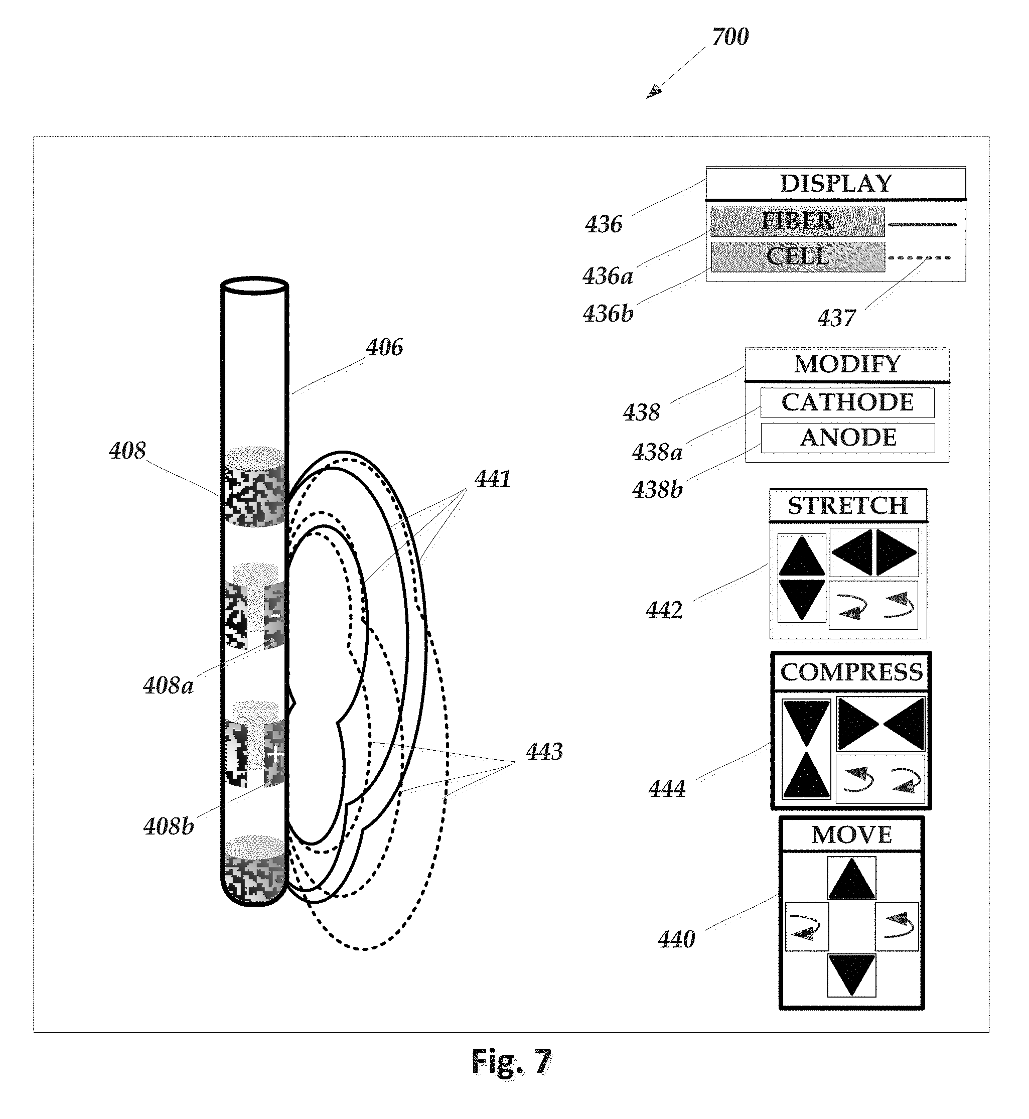
[0080] FIG. 7 illustrates another embodiment of a user interface 700 for visualizing stimulation or for programming an electrical stimulation system. The user interface 700 includes a representation of a portion of the lead 406 with electrodes 408. In the illustrated example, electrode 408a is a cathode and electrode 408b is an anode. In FIG. 7, a set of estimated fiber VOA contour lines 441 and a set of estimated cell VOA contour lines 443. In another embodiment, contour lines for anodic and cathodic VOAs (see, FIGS. 4 and 5) can be displayed. Each contour line of a set corresponds to a different stimulation amplitude. In other embodiments, the contour lines can correspond to changing other stimulation parameters, such as electrode selection, pulse width, pulse duration, or the like, or any combination thereof. In another embodiment, instead of contour lines, a map of the region around the lead can be displayed with shading or coloring that varies according to the stimulation amplitude that is needed to stimulate the region. For example, shading can be darkest for lower amplitude and become lighter for higher amplitude or coloring can range from blue for lower amplitude to red for higher amplitude.
[0081] The user interface also includes the display controls 436, selection control 438, move controls 440, stretch controls 442, and compress controls 444 described above. These controls, however, are now directed to displaying or modifying the fiber VOA contour lines 441 or cell VOA contour lines 443.
[0082] FIG. 8 illustrates another embodiment of a user interface 800 for visualizing stimulation or for programming an electrical stimulation system. The user interface 800 includes a representation of a portion of the lead 406 with electrodes 408. In the illustrated example, electrode 408a is a cathode and electrode 408b is an anode. In FIG. 8, instead of illustrating VOAs, anatomical elements (such as previously identified anatomical structures) are illustrated and are marked based on whether a threshold amount of the particular anatomical element is stimulated by the anode or cathode or not stimulated. In the illustrated embodiments, anatomical element 445 is stimulated by the cathode, anatomical element 447 is stimulated by the anode, and anatomical element is not stimulated. In at least some embodiments, the amount of an anatomical structure that is stimulated is determined using the VOAs described above. In at least some embodiments, a user can set the threshold amount for all anatomical elements. In at least some embodiments, a user can set the threshold amount individually for each anatomical element or subset of anatomical elements.
[0083] The user interface also includes the display controls 436, selection control 438, move controls 440, stretch controls 442, and compress controls 444 described above. When the display or modify controls are operated, the markings on the anatomical elements will be modified based on the modifications to the cathode or anode VOAs.
[0084] In at least some embodiments, any combination of the VOAs and other elements described above for the interfaces illustrated in FIGS. 4 to 8 can be used. In at least some embodiments, multiple VOAs determined using different stimulation conditions or different types of stimulation can be used. For example, any combination of cathodic VOAs, anodic VOAs, fiber VOAs, cell VOAs, terminal VOAs, or the like can be displayed simultaneously or sequentially. Providing these different VOAs can allow a user to compare the stimulation for different conditions. In at least some embodiments, a current, most recent, or user-selected VOA may be highlighted (using, for example, a different color, bold colors or boundaries or contour lines, or shading).
[0085] In at least some embodiments, the user can select a time varying stimulation (for example, stimulation that varies from cathodic to anodic stimulation). Any of the user interfaces described above may include controls for defining the time variation. Any of the user interfaces described above may also include controls that provide an animation of the resulting time-varying VOA. For example, an animated time-varying VOA may transition from anodic to cathodic stimulation (or vice versa). The location of the time-varying VOA may remain constant or may shift over time.
[0086] FIG. 9 is a flowchart of one embodiment of a method of visualizing stimulation or for programming an electrical stimulation system. In step 902, a set of stimulation parameters is received including a selection of at least one anode and at least one cathode. In step 904, cathodic and anodic VOAs are obtained. The system may calculate the VOAs or may receive the VOAs from another system or may determine the VOAs from look-up tables, databases, or the like or may obtain the VOAs in any other suitable manner.
[0087] In step 906, the system displays the electrodes, cathodic VOA, and anodic VOA. For example, any of the user interfaces described above (including, but not limited to the user interfaces illustrated in FIGS. 4 and 5) can be used for displaying these elements. In step 908, modification controls, such as those illustrated in FIGS. 4 and 5, are displayed. In step 910, when the cathodic or anodic VOA is modified using the modification controls, the system determines a modified set of stimulation parameters that will approximate the modified VOA. In optional step 912, a selection of one set of stimulation parameters is received and the system sends the selected set of stimulation parameters to an implantable pulse generator (or other device) to provide stimulation to a patient using the selected stimulation parameters.
[0088] FIG. 10 is a flowchart of another embodiment of a method of visualizing stimulation or for programming an electrical stimulation system. In step 1002, a set of stimulation parameters is received including a selection of at least one anode and at least one cathode. In step 1004, fiber and cell VOAs are obtained. The system may calculate the VOAs or may receive the VOAs from another system or may determine the VOAs from look-up tables, databases, or the like or may obtain the VOAs in any other suitable manner.
[0089] In step 1006, the system displays the electrodes, fiber VOA, and cell VOA. For example, any of the user interfaces described above (including, but not limited to the user interfaces illustrated in FIGS. 6 and 7) can be used for displaying these elements. In step 1008, modification controls, such as those illustrated in FIGS. 6 and 7, are displayed. In step 1010, when the fiber or cell VOA is modified using the modification controls, the system determines a modified set of stimulation parameters that will approximate the modified VOA. In optional step 1012, a selection of one set of stimulation parameters is received and the system sends the selected set of stimulation parameters to an implantable pulse generator (or other device) to provide stimulation to a patient using the selected stimulation parameters.
[0090] FIG. 11 is a flowchart of one embodiment of a method of visualizing stimulation or for programming an electrical stimulation system. In step 1102, a set of stimulation parameters is received including a selection of at least one anode and at least one cathode. Also, a set of anatomical elements is received. In step 1104, the system determines which of the anatomical elements are stimulated, by a threshold amount, by cathodic or anodic stimulation. For example, the system may obtain the cathodic and anodic VOAs and determine which of the anatomical elements have a threshold amount within the respective VOAs.
[0091] In step 1106, the system displays the electrodes and anatomical elements indicating which of the anatomical elements are activated by a threshold amount by cathodic stimulation, which of the anatomical elements are activated by a threshold amount by anodic stimulation, and which of the anatomical elements are not activated. For example, any of the user interfaces described above (including, but not limited to the user interface illustrated in FIG. 8) can be used for displaying these elements. In step 1108, modification controls, such as those illustrated in FIG. 8, are displayed. In step 1110, when the cathodic or anodic VOA is modified using the modification controls, the system determines a modified set of stimulation parameters that will approximate the modified VOA. In optional step 1112, a selection of one set of stimulation parameters is received and the system sends the selected set of stimulation parameters to an implantable pulse generator (or other device) to provide stimulation to a patient using the selected stimulation parameters.
[0092] It will be understood that the system can include one or more of the methods described hereinabove with respect to FIGS. 9-11 in any combination. The methods, systems, and units described herein may be embodied in many different forms and should not be construed as limited to the embodiments set forth herein. Accordingly, the methods, systems, and units described herein may take the form of an entirely hardware embodiment, an entirely software embodiment or an embodiment combining software and hardware aspects. The methods described herein can be performed using any type of processor or any combination of processors where each processor performs at least part of the process.
[0093] It will be understood that each block of the flowchart illustrations, and combinations of blocks in the flowchart illustrations and methods disclosed herein, can be implemented by computer program instructions. These program instructions may be provided to a processor to produce a machine, such that the instructions, which execute on the processor, create means for implementing the actions specified in the flowchart block or blocks disclosed herein. The computer program instructions may be executed by a processor to cause a series of operational steps to be performed by the processor to produce a computer implemented process. The computer program instructions may also cause at least some of the operational steps to be performed in parallel. Moreover, some of the steps may also be performed across more than one processor, such as might arise in a multi-processor computer system. In addition, one or more processes may also be performed concurrently with other processes, or even in a different sequence than illustrated without departing from the scope or spirit of the invention.
[0094] The computer program instructions can be stored on any suitable computer-readable medium including, but not limited to, RAM, ROM, EEPROM, flash memory or other memory technology, CD-ROM, digital versatile disks ("DVD") or other optical storage, magnetic cassettes, magnetic tape, magnetic disk storage or other magnetic storage devices, or any other medium which can be used to store the desired information and which can be accessed by a computing device.
[0095] The above specification provides a description of the structure, manufacture, and use of the invention. Since many embodiments of the invention can be made without departing from the spirit and scope of the invention, the invention also resides in the claims hereinafter appended.
* * * * *
D00000
D00001
D00002
D00003
D00004
D00005
D00006
D00007
D00008
D00009
D00010
XML
uspto.report is an independent third-party trademark research tool that is not affiliated, endorsed, or sponsored by the United States Patent and Trademark Office (USPTO) or any other governmental organization. The information provided by uspto.report is based on publicly available data at the time of writing and is intended for informational purposes only.
While we strive to provide accurate and up-to-date information, we do not guarantee the accuracy, completeness, reliability, or suitability of the information displayed on this site. The use of this site is at your own risk. Any reliance you place on such information is therefore strictly at your own risk.
All official trademark data, including owner information, should be verified by visiting the official USPTO website at www.uspto.gov. This site is not intended to replace professional legal advice and should not be used as a substitute for consulting with a legal professional who is knowledgeable about trademark law.