Posterior Stabilized Prosthesis System
Drury; Nick ; et al.
U.S. patent application number 16/389381 was filed with the patent office on 2019-10-31 for posterior stabilized prosthesis system. The applicant listed for this patent is Zimmer, Inc.. Invention is credited to Jeff Blaylock, Nick Drury.
| Application Number | 20190328535 16/389381 |
| Document ID | / |
| Family ID | 66349376 |
| Filed Date | 2019-10-31 |


View All Diagrams
| United States Patent Application | 20190328535 |
| Kind Code | A1 |
| Drury; Nick ; et al. | October 31, 2019 |
POSTERIOR STABILIZED PROSTHESIS SYSTEM
Abstract
According to one example, a posterior-stabilized femoral prosthesis for a knee arthroplasty. The femoral prosthesis can include medial and lateral condyles, a femoral cam and a recess. The medial and lateral condyles can be shaped to articulate with a tibial articular surface of a tibial bearing component through a range of motion, in which full extension corresponds to zero degrees flexion of a knee joint and positive flexion corresponds to greater than zero degrees flexion of the knee joint. In a sagittal plane, the medial and lateral condyles can define medial and lateral multi-radius curves, respectively. The medial multi-radius curve can have a single common radius swept through a first angular extent to define a single arc length that extends from between substantially -20 degrees flexion to substantially 90 degrees flexion, inclusive.
| Inventors: | Drury; Nick; (Warsaw, IN) ; Blaylock; Jeff; (Fort Wayne, IN) | ||||||||||
| Applicant: |
|
||||||||||
|---|---|---|---|---|---|---|---|---|---|---|---|
| Family ID: | 66349376 | ||||||||||
| Appl. No.: | 16/389381 | ||||||||||
| Filed: | April 19, 2019 |
Related U.S. Patent Documents
| Application Number | Filing Date | Patent Number | ||
|---|---|---|---|---|
| 62664500 | Apr 30, 2018 | |||
| Current U.S. Class: | 1/1 |
| Current CPC Class: | A61F 2002/3863 20130101; A61F 2002/30327 20130101; A61F 2002/30878 20130101; A61F 2/3859 20130101; A61F 2/389 20130101; A61F 2/3836 20130101; A61F 2/3886 20130101; A61F 2002/30518 20130101 |
| International Class: | A61F 2/38 20060101 A61F002/38 |
Claims
1. A posterior-stabilized femoral prosthesis for a knee arthroplasty comprising: medial and lateral condyles shaped to articulate with a tibial articular surface of a tibial bearing component through a range of motion, in which full extension corresponds to zero degrees flexion of a knee joint and positive flexion corresponds to greater than zero degrees flexion of the knee joint, wherein in a sagittal plane the medial and lateral condyles define medial and lateral multi-radius curves, respectively, and wherein the medial multi-radius curve has a single common radius swept through a first angular extent to define a single arc length that extends from between substantially -20 degrees flexion to substantially 90 degrees flexion, inclusive; and a femoral cam and a recess positioned between the medial and lateral condyles, wherein the femoral cam is positioned posterior of the recess.
2. The femoral prosthesis of claim 1, wherein an area of contact between the medial condyle and the tibial articular surface includes a medial dwell point of the tibial articular surface when the femoral prosthesis is in full extension.
3. The femoral prosthesis of claim 2, wherein the area of contact between the medial condyle and the tibial articular surface does not shift position during the range of motion between zero degrees flexion and substantially 100 degrees flexion, and wherein the area of contact includes the medial dwell point during the range of motion between zero degrees flexion and substantially 100 degrees flexion.
4. The femoral prosthesis of claim 1, wherein a posterior portion of the medial and lateral condyles have a thickness of 9 mm.
5. The femoral prosthesis of claim 1, further comprising the tibial bearing component defining the tibial articular surface, the tibial articular surface including: a medial compartment and a lateral compartment configured for articulation with the medial condyle and the lateral condyle of the femoral prosthesis, respectively; and a spine extending proximally from the articular surface and configured to be received in the recess at 0 degrees flexion, the spine spaced posteriorly from an anterior edge of the tibial bearing periphery, the spine disposed between the medial and lateral compartments; wherein the spine and cam make initial contact when the range of motion reaches substantially 100 degrees flexion.
6. The femoral prosthesis of claim 5, wherein the medial compartment is configured to have the medial dwell point a distance between about 52% and about 60% of a total anterior-posterior extent of the tibial bearing component as measured from an anterior most point to a posterior most point of the tibial bearing component.
7. The femoral prosthesis of claim 5, wherein the lateral compartment is configured to have a lateral dwell point a distance between about 59% and about 62% of a total anterior-posterior extent of the tibial bearing component as measured from an anterior most point to a posterior most point of the tibial bearing component.
8. The femoral prosthesis of claim 5, wherein the medial compartment is configured to have between about a 1.05:1 congruence ratio and about a 1.5:1 congruence ratio with the medial condyle through the first angular extent, the congruence ratio comprising a ratio of the similarity between a sagittal radius of the medial compartment and a sagittal radius of the medial condyle.
9. A system of posterior-stabilized knee prostheses for a knee arthroplasty, the system comprising: a tibial bearing component having a tibial articular surface with a medial compartment and a lateral compartment, wherein the tibial bearing component has a spine extending proximally from the tibial articular surface and positioned between the medial and lateral compartments, and wherein the medial compartment has a medial dwell point; a femoral prosthesis having a cam and medial and lateral condyles spaced to either side of the cam, wherein the medial condyle is configured for articulation with the medial compartment and lateral condyle is configured for articulation with the lateral compartment, and wherein femoral prosthesis is configured to articulate through a range of motion relative to the tibial bearing component, such range of motion includes a full extension that corresponds to zero degrees flexion of a knee joint and positive flexion that corresponds to greater than zero degrees flexion of the knee joint, and wherein an area of contact between the medial condyle and the medial compartment does not shift position during the range of motion between zero degrees flexion and substantially 100 degrees flexion and the area of contact includes the medial dwell point during the range of motion between zero degrees flexion and substantially 100 degrees flexion.
10. The system of claim 9, wherein in a sagittal plane the medial and lateral condyles define medial and lateral multi-radius curves, respectively, and wherein the medial multi-radius curve has a single common radius swept through a first angular extent to define a single arc length that extends from between substantially -20 degrees flexion to substantially 90 degrees flexion, inclusive.
11. The system of claim 9, wherein a posterior portion of the medial and lateral condyles have a thickness of 9 mm.
12. The system of claim 9, wherein the spine and cam are both configured to make initial contact when the range of motion reaches substantially 100 degrees flexion.
13. The system of claim 9, wherein the medial compartment is configured to have the medial dwell point a distance between about 52% and about 60% of a total anterior-posterior extent of the tibial bearing component as measured from an anterior most point to a posterior most point of the tibial bearing component.
14. The system of claim 9, wherein the lateral compartment is configured to have a lateral dwell point a distance between about 59% and about 62% of a total anterior-posterior extent of the tibial bearing component as measured from an anterior most point to a posterior most point of the tibial bearing component.
15. The system of claim 9, wherein the medial compartment is configured to have between about a 1.05:1 congruence ratio and about a 1.5:1 congruence ratio with the medial condyle through the first angular extent, the congruence ratio comprising a ratio of the similarity between a sagittal radius of the medial compartment and a sagittal radius of the medial condyle.
16. A system of posterior-stabilized knee prostheses for a knee arthroplasty, the system comprising: a tibial bearing component having a tibial articular surface with a medial compartment and a lateral compartment, wherein the tibial bearing component has a spine extending proximally from the tibial articular surface and positioned between the medial and lateral compartments, and wherein the medial compartment has a medial dwell point; a femoral prosthesis having a cam and medial and lateral condyles spaced to either side of the cam, wherein the medial condyle is configured for articulation with the medial compartment and lateral condyle is configured for articulation with the lateral compartment, and wherein femoral prosthesis is configured to articulate through a range of motion relative to the tibial bearing component, such range of motion includes a full extension that corresponds to zero degrees flexion of a knee joint and positive flexion that corresponds to greater than zero degrees flexion of the knee joint, wherein an area of contact between the medial condyle and the medial compartment includes the medial dwell point when the femoral prosthesis is in full extension, and wherein the spine and cam are both configured to make initial contact when the range of motion reaches substantially 100 degrees flexion.
17. The system of claim 16, wherein the area of contact between the medial condyle and the tibial articular surface does not shift during the range of motion between zero degrees flexion and substantially 100 degrees flexion and includes the medial dwell point during the range of motion between zero degrees flexion and substantially 100 degrees flexion.
18. The system of claim 16, wherein in a sagittal plane the medial and lateral condyles define medial and lateral multi-radius curves, respectively, and wherein the medial multi-radius curve has a single common radius swept through a first angular extent to define a single arc length that extends from between substantially -20 degrees flexion to substantially 90 degrees flexion, inclusive.
19. The system of claim 16, wherein the medial compartment is configured to have the medial dwell point a distance between about 52% and about 60% of a total anterior-posterior extent of the tibial bearing component as measured from an anterior most point to a posterior most point of the tibial bearing component.
20. The system of claim 16, wherein a posterior portion of the medial and lateral condyles have a thickness of 9 mm.
Description
CLAIM OF PRIORITY
[0001] This application claims the benefit of U.S. Provisional Patent Application Ser. No. 62/664,500, filed on Apr. 30, 2018, the benefit of priority of which is claimed hereby, and which is incorporated by reference herein in its entirety.
FIELD
[0002] The present subject matter relates to orthopedic procedures and, more particularly, to prostheses, systems and methods used in knee arthroplasties.
BACKGROUND
[0003] Orthopedic procedures and prostheses are commonly utilized to repair and/or replace damaged bone and tissue in the human body. For example, a knee arthroplasty can be used to restore natural knee function by repairing damaged or diseased articular surfaces of the femur and/or tibia. An incision is made into the knee joint to expose the bones comprising the joint. Cut guides are used to guide the removal of the articular surfaces that are to be replaced. Prostheses are used to replicate the articular surfaces. Knee prostheses can include a femoral prosthesis implanted on the distal end of the femur, which articulates with a tibial bearing component and a tibial component implanted on the proximal end of a tibia to replicate the function of a healthy natural knee. Various types of procedures are known including a total knee arthroplasty (TKA), where all of the articulating compartments of the joint are repaired with prosthetic components.
OVERVIEW
[0004] This disclosure pertains generally to prostheses and systems for knee arthroplasty. The present inventors have recognized, among other things, improvements to femoral prostheses (sometimes called femoral prostheses) and tibial bearing components (sometimes called tibial bearing prostheses, tibial bearings, bearings, poly or bearing components). In particular, the present inventors have focused on posterior-stabilized (PS) prostheses, which include a spine on the tibial bearing component and a cam on the femoral prosthesis that are configured to interact together when the femoral prosthesis is in flexion to provide further stability to the knee joint. PS prostheses are typically utilized in instances where one or more of the cruciate ligaments (e.g, ACL and PCL) of the knee joint have suffered degeneration and must be eliminated. PS prostheses have particular design considerations and kinematics, which differ from other types of knee prostheses such as ultra-congruent (UC) and cruciate-retaining (CR) prostheses, for example.
[0005] Considering criteria specific to PS prostheses, the present inventors have designed femoral prostheses and tibial bearing components that allow for greater joint stability, improved kinematics during flexion of the knee joint, and increased compatibility with other known prosthesis designs. Thus, with regard to the femoral prostheses disclosed the present inventors propose an example where the medial and lateral condyles are shaped to articulate with a tibial articular surface of a tibial bearing component through a range of motion. In a sagittal plane, the medial and lateral condyles can define medial and lateral multi-radius curves, respectively. The medial multi-radius curve can have a single common radius swept through a first angular extent to define a single arc length that extends from between substantially -20 degrees flexion to substantially 90 degrees flexion, inclusive. A posterior portion (shown and described subsequently) of the medial and lateral condyles can have a thickness of 9 mm. In one example, the medial multi-radius curve can have a second radius swept through a second angular extent to define a second arc length that extends from between substantially 90 degrees flexion to beyond 100 degrees flexion. The medial and lateral condyles can be symmetrically shaped such that lateral condyle can have a lateral multi-radius curve of a same shape as the medial multi-radius curve. Thus, the lateral multi-radius curve can have the single common radius swept through the first angular extent to define the single arc length that extends from between substantially -20 degrees flexion to substantially 90 degrees flexion, inclusive.
[0006] According to disclosed examples, in combination the femoral prosthesis and the tibial bearing component can be configured such that an area of contact between the medial condyle and the tibial articular surface includes a medial dwell point of the tibial articular surface when the femoral prosthesis is in full extension. The femoral prosthesis and the tibial bearing component can be configured such that the area of contact between the medial condyle and the tibial articular surface does not shift during the range of motion between zero degrees flexion and substantially 100 degrees flexion and includes the medial dwell point during the range of motion between zero degrees flexion and substantially 100 degrees flexion. A spine of the tibial bearing component and a cam of the femoral prosthesis can make initial contact when the range of motion reaches substantially 100 degrees flexion. A medial compartment of the tibial bearing component can be configured to have between about a 1.05:1 congruence ratio and about a 1.5:1 congruence ratio with the medial condyle through the first angular extent, the congruence ratio can comprise a ratio of the similarity between a sagittal radius of the medial compartment and the single common radius of the medial condyle.
[0007] Regarding the tibial bearing component, the medial compartment can be configured to have the medial dwell point a distance between about 52% and about 60% of a total anterior-posterior extent of the tibial bearing component as measured from an anterior most point to a posterior most point of the tibial bearing component. The lateral compartment can be configured to have a lateral dwell point a distance between about 59% and about 62% of a total anterior-posterior extent of the tibial bearing component as measured from an anterior most point to a posterior most point of the tibial bearing component.
[0008] Additionally, the present inventors have designed a family of tibial bearing components that can have at least eleven different stock sizes so as to achieve more compatible combinations when used with a family of tibia prostheses that can have at least nine different stock sizes and a family of femoral prostheses that can have at least twelve different stock sizes. Due to the number of components and the designed compatibility between various sizes in the respective families, thirty three combinations of the at least eleven different stock sizes of the family of tibial bearing components can be compatible for operable use with the at least twelve different stock sizes of the family of femoral prostheses.
[0009] To further illustrate the apparatuses and systems disclosed herein, the following non-limiting examples are provided:
[0010] Example 1 is a posterior-stabilized femoral prosthesis for a knee arthroplasty. The femoral prosthesis can include medial and lateral condyles, a femoral cam and a recess. The medial and lateral condyles can be shaped to articulate with a tibial articular surface of a tibial bearing component through a range of motion, in which full extension corresponds to zero degrees flexion of a knee joint and positive flexion corresponds to greater than zero degrees flexion of the knee joint. In a sagittal plane, the medial and lateral condyles can define medial and lateral multi-radius curves, respectively. The medial multi-radius curve can have a single common radius swept through a first angular extent to define a single arc length that extends from between substantially -20 degrees flexion to substantially 90 degrees flexion, inclusive. The femoral cam and the recess can be positioned between the medial and lateral condyles. The femoral cam can be positioned posterior of the recess.
[0011] In Example 2, the femoral prosthesis of Example 1, wherein an area of contact can be between the medial condyle and the tibial articular surface can include a medial dwell point of the tibial articular surface when the femoral prosthesis is in full extension.
[0012] In Example 3, the femoral prosthesis of Example 2, wherein the area of contact between the medial condyle and the tibial articular surface may not shift position during the range of motion between zero degrees flexion and substantially 100 degrees flexion, and wherein the area of contact can include the medial dwell point during the range of motion between zero degrees flexion and substantially 100 degrees flexion.
[0013] In Example 4, the femoral prosthesis of any one or any combination of Examples 1-3, wherein a posterior portion of the medial and lateral condyles can have a thickness of 9 mm.
[0014] In Example 5, the femoral prosthesis of any one or any combination of Examples 1-4, further comprising the tibial bearing component defining the tibial articular surface, the tibial articular surface can optionally include: a medial compartment and a lateral compartment configured for articulation with the medial condyle and the lateral condyle of the femoral prosthesis, respectively; and a spine extending proximally from the articular surface and configured to be received in the recess at 0 degrees flexion, the spine spaced posteriorly from an anterior edge of the tibial bearing periphery, the spine disposed between the medial and lateral compartments; wherein the spine and cam make initial contact when the range of motion reaches substantially 100 degrees flexion.
[0015] In Example 6, the femoral prosthesis of Example 5, wherein the medial compartment can be configured to have the medial dwell point a distance between about 52% and about 60% of a total anterior-posterior extent of the tibial bearing component as measured from an anterior most point to a posterior most point of the tibial bearing component.
[0016] In Example 7, the femoral prosthesis of Example 5, wherein the lateral compartment can be configured to have a lateral dwell point a distance between about 59% and about 62% of a total anterior-posterior extent of the tibial bearing component as measured from an anterior most point to a posterior most point of the tibial bearing component.
[0017] In Example 8, the femoral prosthesis of any one or any combination of Example 5-7, wherein the medial compartment can be configured to have between about a 1.05:1 congruence ratio and about a 1.5:1 congruence ratio with the medial condyle through the first angular extent, the congruence ratio comprising a ratio of the similarity between a sagittal radius of the medial compartment and a sagittal radius of the medial condyle.
[0018] In Example 9, a system of posterior-stabilized knee prostheses for a knee arthroplasty, the system can optionally comprise: a tibial bearing component having a tibial articular surface with a medial compartment and a lateral compartment, wherein the tibial bearing component has a spine extending proximally from the tibial articular surface and positioned between the medial and lateral compartments, and wherein the medial compartment has a medial dwell point; a femoral prosthesis having a cam and medial and lateral condyles spaced to either side of the cam, wherein the medial condyle is configured for articulation with the medial compartment and lateral condyle is configured for articulation with the lateral compartment, and wherein femoral prosthesis is configured to articulate through a range of motion relative to the tibial bearing component, such range of motion includes a full extension that corresponds to zero degrees flexion of a knee joint and positive flexion that corresponds to greater than zero degrees flexion of the knee joint, and wherein an area of contact between the medial condyle and the medial compartment does not shift position during the range of motion between zero degrees flexion and substantially 100 degrees flexion and the area of contact includes the medial dwell point during the range of motion between zero degrees flexion and substantially 100 degrees flexion.
[0019] In Example 10, the system of Example 9, wherein in a sagittal plane the medial and lateral condyles can define medial and lateral multi-radius curves, respectively, and wherein the medial multi-radius curve can have a single common radius swept through a first angular extent to define a single arc length that extends from between substantially -20 degrees flexion to substantially 90 degrees flexion, inclusive.
[0020] In Example 11, the system of any one or any combination of Examples 9-10, wherein a posterior portion of the medial and lateral condyles can have a thickness of 9 mm.
[0021] In Example 12, the system of any one or any combination of Examples 9-11, wherein the spine and cam can both be configured to make initial contact when the range of motion reaches substantially 100 degrees flexion.
[0022] In Example 13, the system of any one or any combination of Examples 9-12, wherein the medial compartment can be configured to have the medial dwell point a distance between about 52% and about 60% of a total anterior-posterior extent of the tibial bearing component as measured from an anterior most point to a posterior most point of the tibial bearing component.
[0023] In Example 14, the system of any one or any combination of Examples 9-12, wherein the lateral compartment can be configured to have a lateral dwell point a distance between about 59% and about 62% of a total anterior-posterior extent of the tibial bearing component as measured from an anterior most point to a posterior most point of the tibial bearing component.
[0024] In Example 15, the system of any one or any combination of Examples 9-14, wherein the medial compartment can be configured to have between about a 1.05:1 congruence ratio and about a 1.5:1 congruence ratio with the medial condyle through the first angular extent, the congruence ratio comprising a ratio of the similarity between a sagittal radius of the medial compartment and a sagittal radius of the medial condyle.
[0025] In Example 16, a system of posterior-stabilized knee prostheses for a knee arthroplasty, the system can optionally comprise: a tibial bearing component having a tibial articular surface with a medial compartment and a lateral compartment, wherein the tibial bearing component has a spine extending proximally from the tibial articular surface and positioned between the medial and lateral compartments, and wherein the medial compartment has a medial dwell point; a femoral prosthesis having a cam and medial and lateral condyles spaced to either side of the cam, wherein the medial condyle is configured for articulation with the medial compartment and lateral condyle is configured for articulation with the lateral compartment, and wherein femoral prosthesis is configured to articulate through a range of motion relative to the tibial bearing component, such range of motion includes a full extension that corresponds to zero degrees flexion of a knee joint and positive flexion that corresponds to greater than zero degrees flexion of the knee joint, wherein an area of contact between the medial condyle and the medial compartment includes the medial dwell point when the femoral prosthesis is in full extension, and wherein the spine and cam are both configured to make initial contact when the range of motion reaches substantially 100 degrees flexion.
[0026] In Example 17, the system of Example 16, wherein the area of contact between the medial condyle and the tibial articular surface may not shift during the range of motion between zero degrees flexion and substantially 100 degrees flexion and can include the medial dwell point during the range of motion between zero degrees flexion and substantially 100 degrees flexion.
[0027] In Example 18, the system of any one or any combination of Examples 16-17, wherein in a sagittal plane the medial and lateral condyles can define medial and lateral multi-radius curves, respectively, and wherein the medial multi-radius curve can have a single common radius swept through a first angular extent to define a single arc length that extends from between substantially -20 degrees flexion to substantially 90 degrees flexion, inclusive.
[0028] In Example 19, the system of any one or any combination of Examples 16-18, wherein the medial compartment can be configured to have the medial dwell point a distance between about 52% and about 60% of a total anterior-posterior extent of the tibial bearing component as measured from an anterior most point to a posterior most point of the tibial bearing component.
[0029] In Example 20, the system of any one or any combination of Examples 16-19, wherein a posterior portion of the medial and lateral condyles can have a thickness of 9 mm.
[0030] In Example 21, the apparatuses or systems of any one or any combination of Examples 1-20 can optionally be configured such that all elements or options recited are available to use or select from.
[0031] These and other examples and features of the present apparatuses and systems will be set forth in part in the following Detailed Description. This Overview is intended to provide non-limiting examples of the present subject matter--it is not intended to provide an exclusive or exhaustive explanation. The Detailed Description below is included to provide further information about the present apparatuses and systems.
BRIEF DESCRIPTION OF THE DRAWINGS
[0032] In the drawings, which are not necessarily drawn to scale, like numerals can describe similar components in different views. Like numerals having different letter suffixes can represent different instances of similar components. The drawings illustrate generally, by way of example, but not by way of limitation, various examples discussed in the present document.
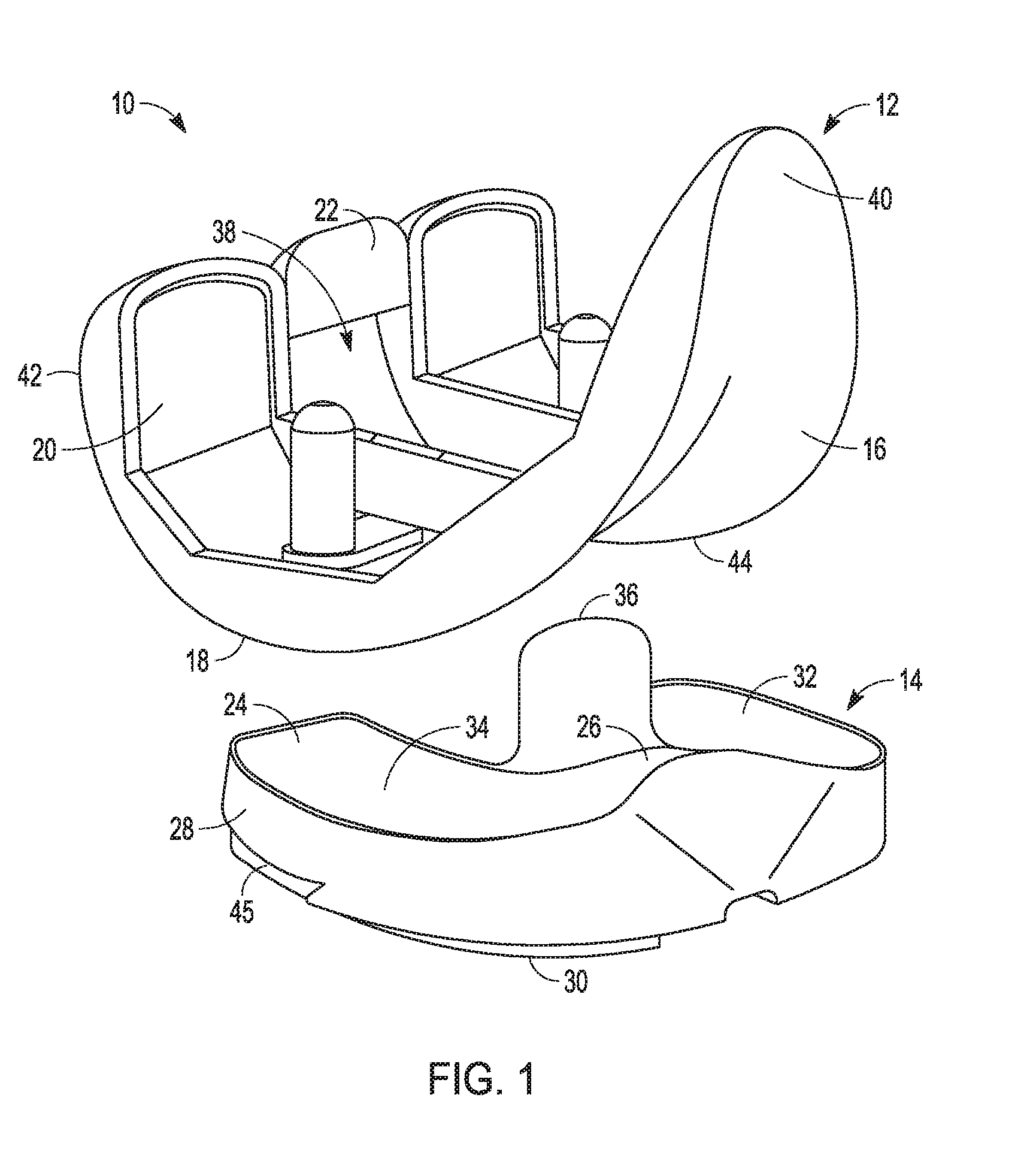
[0033] FIG. 1 is an exploded view of a femoral prosthesis and a tibial bearing component in accordance with an example of the present application.
[0034] FIG. 2 is a perspective view of the femoral prostheses assembled with the tibial bearing component with the knee joint in full extension in accordance with an example of the present application.
[0035] FIG. 2A is a plan view of posterior portions of the femoral prosthesis and the tibial bearing component of FIG. 2.
[0036] FIG. 2B is a plan view from a proximal position of the femoral prosthesis and the tibial bearing component of FIG. 2.
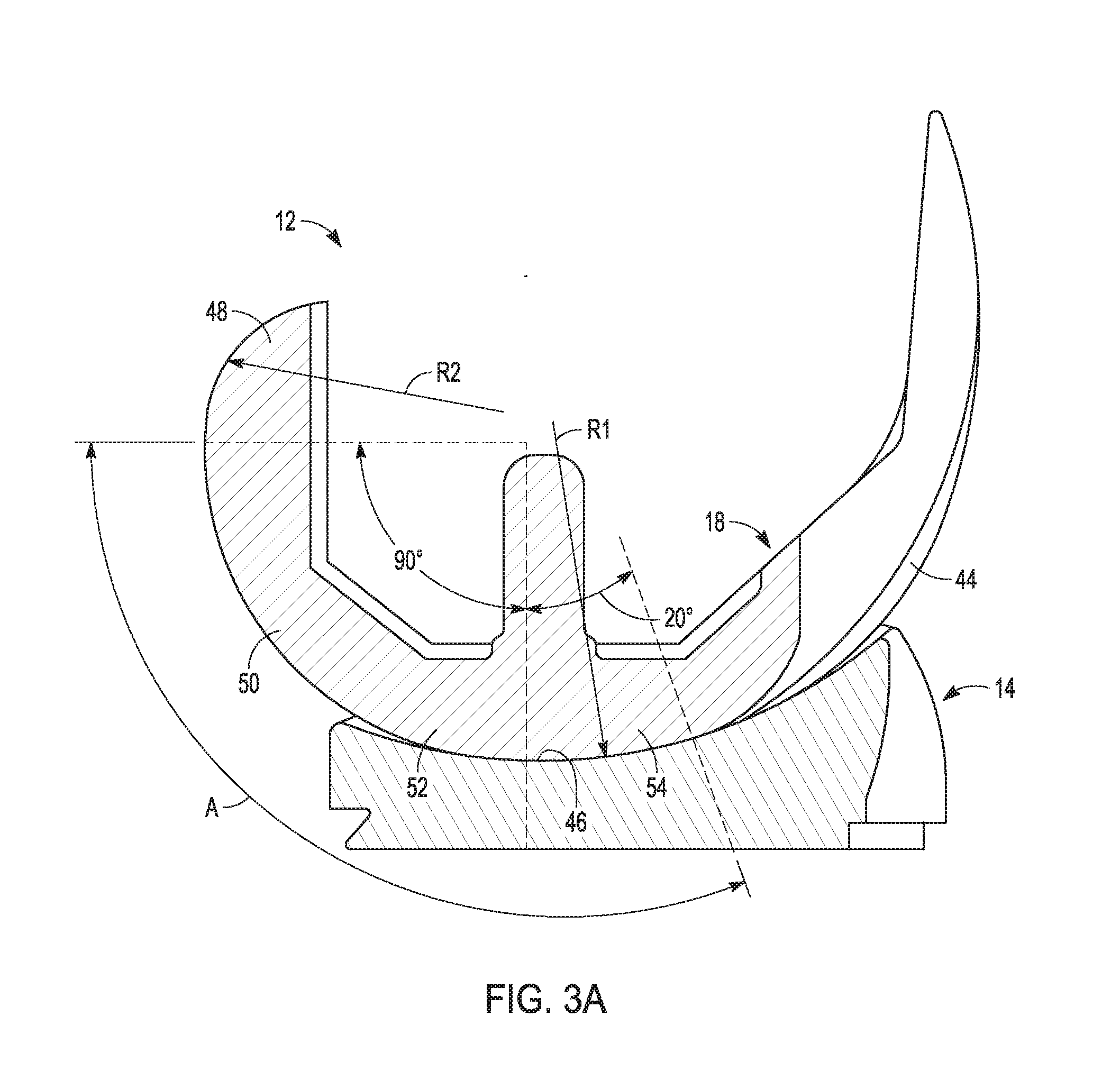
[0037] FIG. 3A is a cross-sectional view of the femoral prosthesis and the tibial bearing component of FIG. 2 taken in a sagittal plane along a medial multi-radius curve of the femoral prosthesis in accordance with an example of the present application.
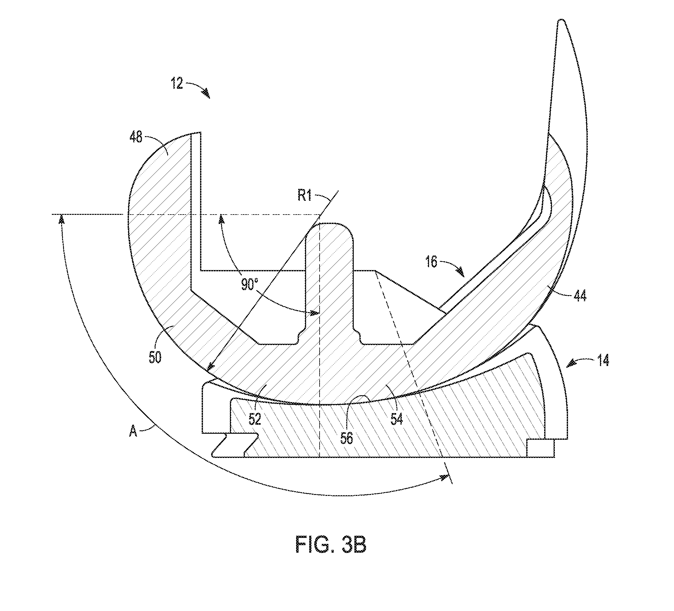
[0038] FIG. 3B is a cross-sectional view of the femoral prosthesis and the tibial bearing component of FIG. 2 taken in the sagittal plane along a lateral multi-radius curve of the femoral prosthesis in accordance with an example of the present application.
[0039] FIG. 4 is a table comparing radii of curvatures for various portions of the medial multi-radius curve of the femoral prosthesis as presently disclosed with other commercially available femoral prostheses in accordance with an example of the present application.
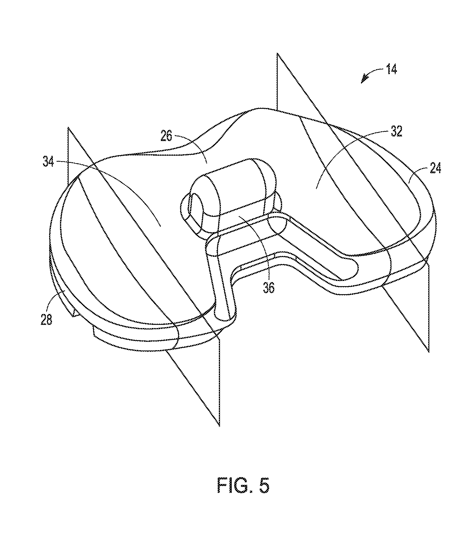
[0040] FIG. 5 is a perspective view of the tibial bearing component according to one example of the present application.
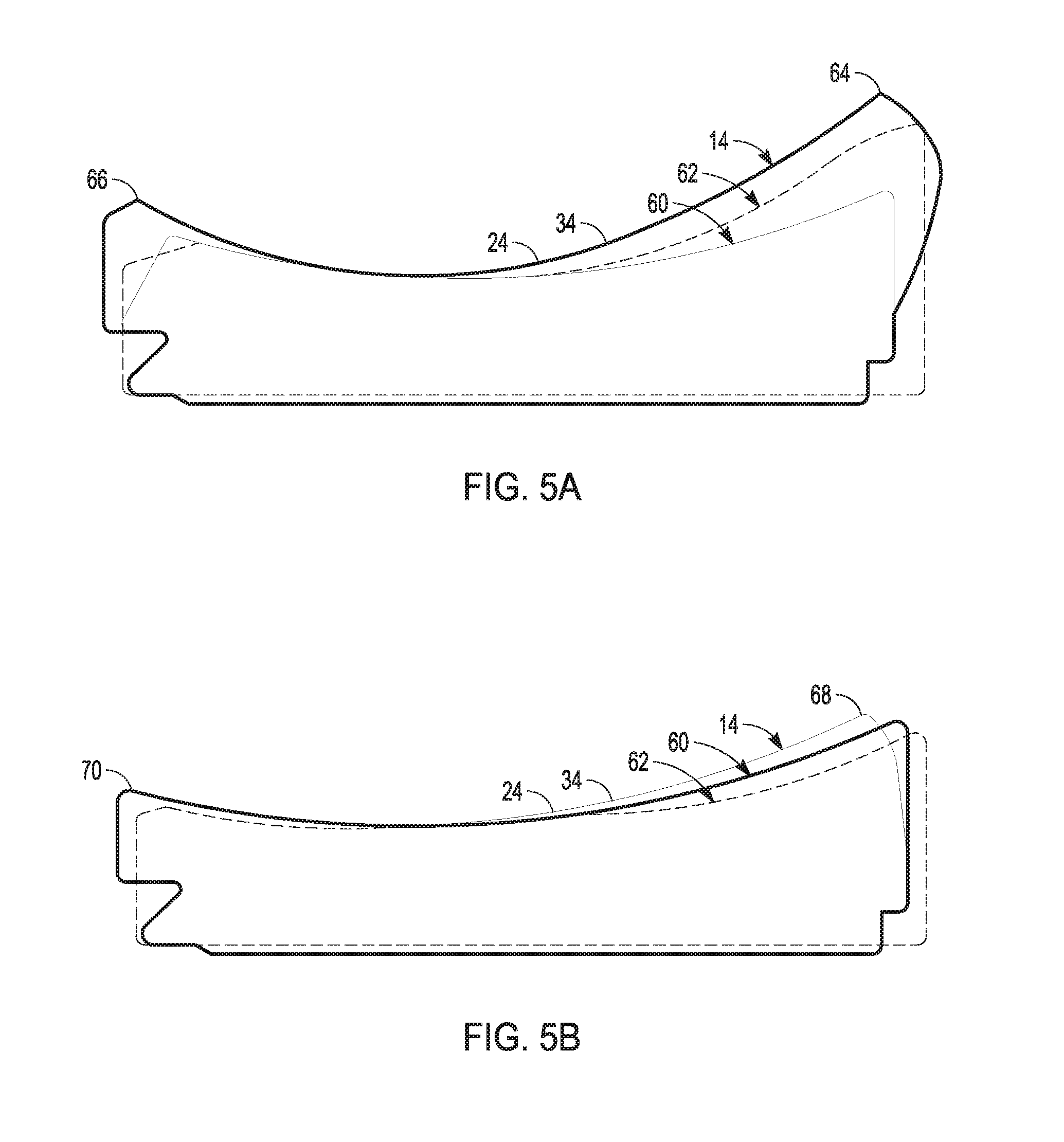
[0041] FIG. 5A is a view in a sagittal plane extending through the medial compartment showing an outline of shape of the articular surface and other portions for various tibial bearing components including the tibial bearing component of FIGS. 2 and 5 in comparison with two commercially available tibial bearing components of similar size according to one example of the present application.
[0042] FIG. 5B is a view in a sagittal plane extending through the lateral compartment showing an outline of shape of the articular surface and other portions for various tibial bearing components including the tibial bearing component of FIGS. 2 and 5 in comparison with two commercially available tibial bearing components of similar size according to one example of the present application.
[0043] FIG. 5C is a view in a sagittal plane extending through the spine and intercondylar space showing an outline of shape of the spine and intercondylar space for various tibial bearing components including the tibial bearing component of FIGS. 2 and 5 in comparison with two commercially available tibial bearing components of similar size according to one example of the present application.
[0044] FIG. 6 shows a view in a sagittal plane extending through the cam showing an outline of shape of the cam for various tibial bearing components including the femoral prostheses of FIG. 2 in comparison with two commercially available femoral prostheses of similar size according to one example of the present application.
[0045] FIGS. 7A and 7B illustrate laxity envelopes and allowable anterior-posterior translation of the femoral prosthesis with the tibial bearing component of FIG. 2 as compared with the two commercially available femoral prosthesis and tibial bearing component systems in accordance with an example of the present application.
[0046] FIGS. 8A and 8B illustrate a width of the laxity envelopes of the femoral prosthesis with the tibial bearing component of FIG. 2 as compared with the two commercially available femoral prosthesis and tibial bearing component systems in accordance with an example of the present application.
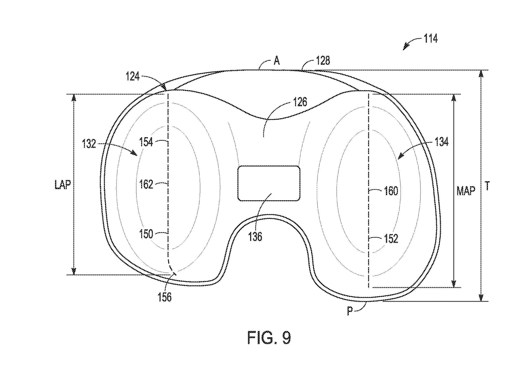
[0047] FIG. 9 is a plan view of a proximal surface of the tibial bearing component as previously disclosed further illustrating features such as the spine, the medial compartment and the lateral compartment in accordance with an example of the present application.
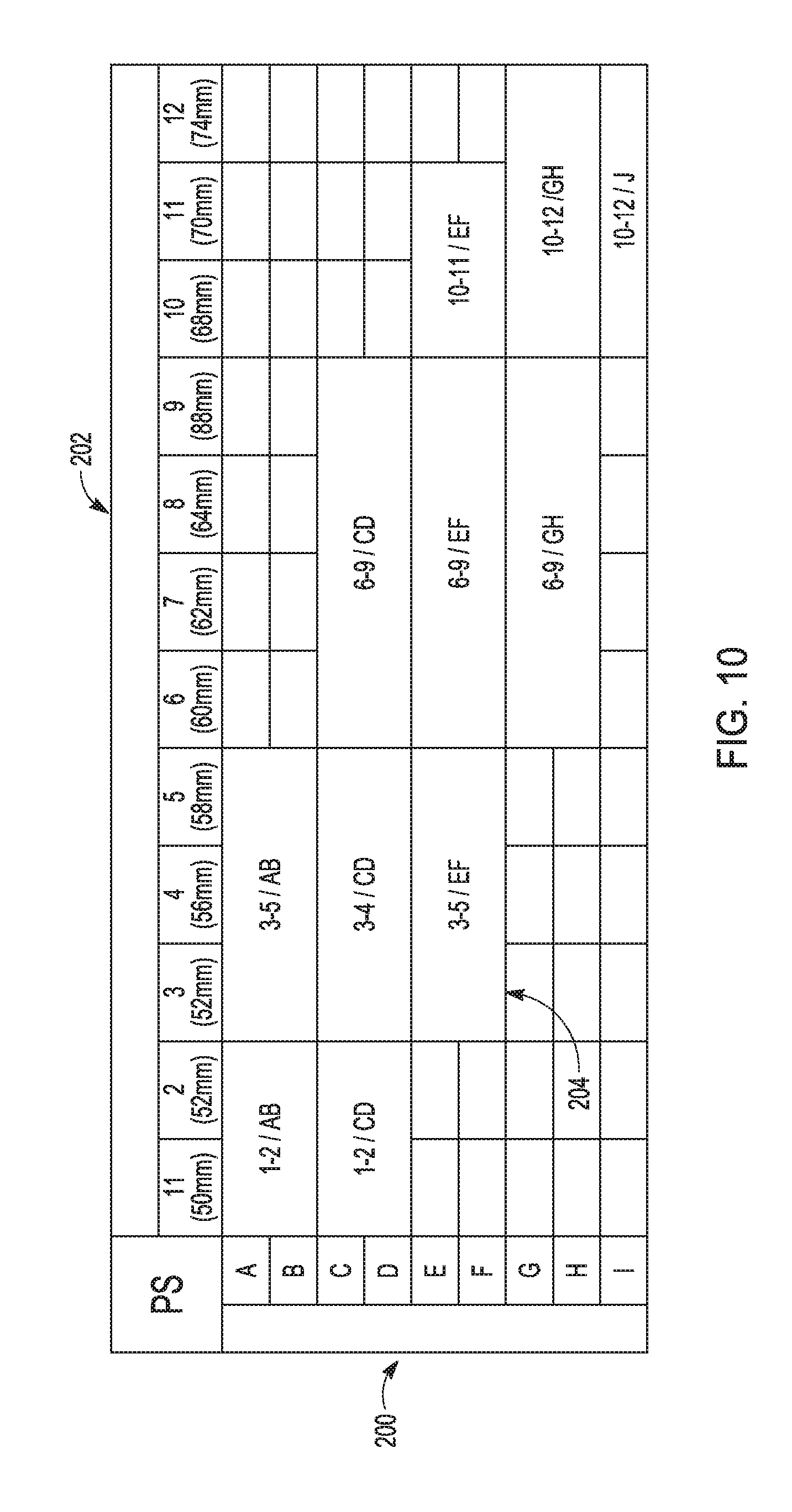
[0048] FIG. 10 shows a sizing chart for a family of tibial bearing components relative to a family of femoral prostheses, tibial prostheses and tibial bearing components in accordance with an example of the present application.
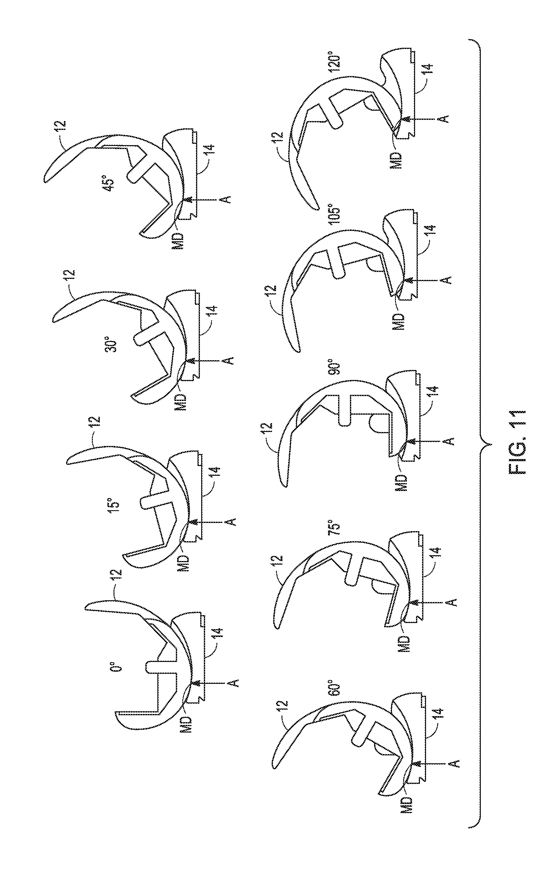
[0049] FIG. 11 shows sagittal views illustrating contact areas as indicated by arrows between the medial femoral condyle of the femoral prosthesis and the medial compartment of the tibial bearing component shown at different degrees of flexion of the femoral prosthesis relative to the tibial bearing component in accordance with an example of the present application.
DETAILED DESCRIPTION
[0050] The present application relates femoral prostheses, tibial bearing components and systems including such prostheses and components.
[0051] In a TKA, both of the medial and lateral condyles of the femur can be resected. Similarly, the tibia can be resected to remove the medial articular surface and the lateral articular surface using a cutting apparatus. Other portions of the knee, e.g., the intercondylar eminence, can also be removed. Depending on the type of TKA, features such as the ligaments can be spared or can also be removed. As discussed above, in a PS TKA, the ligaments such as the posterior cruciate ligament PCL are removed. Prostheses can be implanted on the femur and the tibia and a bearing component can be placed between the femoral prosthesis and the tibial prosthesis to provide for the replaced articular surfaces.
[0052] FIG. 1 shows a system 10 that includes a femoral prosthesis 12 and a tibial bearing component 14. The femoral prosthesis 12 can include a lateral condyle 16, a medial condyle 18, bone interfacing surfaces 20, and a cam 22. The tibial bearing component 14 can include an articular surface 24, an intercondylar region 26, a periphery 28 and a distal surface 30. The articular surface 24 can include a lateral compartment 32 and a medial compartment 34. The intercondylar region 26 can include a spine 36.
[0053] The femoral prosthesis 12 can be implanted on a respected femur (not shown) via the bone interfacing surfaces 20. The tibial bearing component 14 can attach to a tibial prosthesis (not shown) that is implanted on a resected tibia (not shown). The femoral prosthesis 12 and the tibial bearing component 14 are configured to articulate together through a range of motion for the femoral prosthesis 12. This range of motion can include knee joint flexion and extension as will be illustrated and described subsequently.
[0054] The lateral condyle 16 is spaced from the medial condyle 18 in a medial-lateral direction by a sulcus space and in some portions of the femoral prosthesis 12 by a recess 38. The femoral prosthesis 12 can have an anterior end portion 40 and a posterior end portion 42. The cam 22 can be disposed at the posterior end portion 42 proximal of the recess 38. The cam 22 can extend between the lateral condyle 16 and the medial condyle 18.
[0055] The lateral condyle 16 can be arcuate in shape having a radius of curvature along an articular surface 44 as will be illustrated and discussed subsequently. The lateral condyle 16 can be configured to be received by the lateral compartment 32 for articulation therewith when the femoral prosthesis 12 is assembled atop the tibial bearing component 14 such as shown in FIG. 2. Similarly, the medial condyle 18 can be arcuate in shape along the articular surface 44 having a radius of curvature as will be illustrated and discussed subsequently. The medial condyle 18 can be configured to be received by the medial compartment 34 for articulation therewith when the femoral prosthesis 12 is assembled atop the tibial bearing component 14 such as shown in FIG. 2.
[0056] According to the example of FIG. 1, the lateral condyle 16 can be symmetrically shaped relative to the medial condyle 18. This results in the lateral condyle 16 and medial condyle 18 sharing the same radius of curvature resulting in each having a same shape for a multi-radius curve as shown and described subsequently.
[0057] For the tibial bearing component 14, the articular surface 24 comprises a proximal surface for the tibial bearing component 14 and can be configured to interface with the lateral and medial condyles 16 and 18. The articular surface 24 and the intercondylar region 26 can be opposed to and spaced from the distal surface 30 by the periphery 28. The periphery 28 and/or the distal surface 30 can include features 45 for attachment to the tibial prosthesis. The features 45 can be shaped to mate with corresponding features of a sidewall of a tibial tray (now shown) such as to create an interference fit, for example.
[0058] As discussed above, the articular surface 24 can include the lateral compartment 32 and the medial compartment 34. The lateral and medial compartments 32 and 34 can be dish shaped with a curvature in a proximal-distal and the medial-lateral directions. The lateral compartment 32 can be spaced in the medial-lateral direction from the medial compartment 34.
[0059] The intercondylar region 26 can be positioned between the lateral and medial compartments 32 and 34. The intercondylar region 26 can comprise a raised prominence relative to the lateral and medial compartments 32 and 34. The spine 36 can be part of the intercondylar region 26 positioned between the lateral and medial compartments 32 and 34. The spine 36 can also be spaced posteriorly from an anterior edge of the periphery 28. The spine 36 can comprise a projection extending generally proximally from the intercondylar region 26. The spine 36 can be canted anterior-to-posterior as will be subsequently shown. The spine 36 can configured to be received in the recess 38 at 0 degrees flexion as shown in FIGS. 2A and 2B.
[0060] Further details relating to aspects of the construct of the femoral prosthesis 12 and tibial bearing component 14 can found in U.S. Pat. Nos. 8,858,643, 9,072,607, 8,690,954, 8,764,838, 8,932,365 and United States Application Publication No. 2012/0323336, the disclosures of which are incorporated by reference in their entirety.
[0061] According to one example, the femoral component 12 can be designed to be compatible with other commercially available tibial bearing components such as those of the Zimmer Biomet Persona.RTM. knee system manufactured by Zimmer Biomet Holding, Inc. of Warsaw, Ind. Similarly, according to one example, the tibial bearing component 14 can be designed to be compatible with other commercially available femoral prostheses such as those of the Zimmer Biomet Persona.RTM. knee system.
[0062] FIGS. 2 to 2B show the femoral prosthesis 12 assembled atop the tibial bearing component 14. In FIGS. 2 to 2B, the knee joint is illustrated in full extension (corresponding to 0 degrees flexion).
[0063] As shown in the example of FIGS. 2-2B, the tibial bearing component 14 is compatible with and configured for operable use to articulate with the femoral prosthesis 12. In particular, the articular surface 24 of the tibial bearing component 14 can be configured to receive the articular surface 44 of the femoral prosthesis 12 thereon and can be configured to allow for articular movement of the femoral prosthesis 12 relative thereto through the range of motion in a manner that simulates the kinematics of a natural knee (e.g., allow for rollback of the femoral prosthesis 12 in flexion including anterior-posterior translation, engagement of the spine 36 with the cam 22 (features shown in FIGS. 2A and 2B), etc.)
[0064] FIG. 3A shows a sagittal cross-section of the tibial bearing component 14 and the femoral prosthesis 12 with the cross-section taken through the medial condyle 18. In FIG. 3A, the medial condyle 18 defines a medial multi-radius curve 46 that is part of the articular surface 44.
[0065] As shown in FIG. 3A, the medial condyle 18 can have a high flex portion 48, a posterior portion 50, an extension to mid-flexion portion 52, and a part of an anterior region 54. As shown in the example of FIG. 3, the posterior portion 50 and the extension to mid-flexion portion 52 can share a single common radius R1. Indeed, in the example of FIG. 3A, the posterior portion 50, the extension to mid-flexion portion 52, and the part of the anterior region 54 can share the single common radius R1.
[0066] In FIG. 3A, the posterior portion 50 extends to 90 degrees flexion, inclusive. The high flex portion 48 extends between substantially 90 degrees flexion to 170 degrees. The extension to mid-flexion portion 52 can extend from the posterior portion 50 to 0 degrees flexion (0 degrees flexion comprising full extension). The part of the anterior region 54 can extend from substantially 0 degrees flexion to -20 degrees flexion, inclusive, for example.
[0067] According to the example shown, the medial multi-radius curve 46 can have the single common radius R1 swept through a first angular extent to define a single arc length A that extends from between substantially -20 degrees flexion to substantially 90 degrees flexion, inclusive. The single arc length A includes the posterior portion 50, the extension to mid-flexion portion 52 and the part of the anterior region 54. Thus, the medial multi-radius curve 46 can have the single common radius R1 swept through a first portion of the first angular extent to define a first part the single arc length A that extends from between substantially 0 degrees flexion to substantially 90 degrees flexion. Additionally, the medial multi-radius curve 46 can have the single common radius R1 swept through a second portion of the first angular extent to define a second part the single arc length A that extends from between substantially -20 degrees flexion to substantially 0 degrees flexion.
[0068] In the example of FIG. 3A, the high flex portion 48 can have a second radius R2 that differs from that of the single common radius R1. In particular, the second radius R2 can be smaller than the single common radius R1. Such a configuration can avoid or reduce the likelihood of a kinematic conflict between the cam 22 (features shown in FIGS. 2A and 2B) and the spine 36. This can allow for a transition region in the high flex portion 48 of substantially 10 degrees of flexion (as measured from the end of the posterior portion 50 at substantially 90 degrees) as the spine 36 and the cam can be configured to make initial contact with the range of motion reaches substantially 100 degrees flexion with the tibial bearing component 14 positioned at a 5 degree anterior-to-posterior slope. If the tibial bearing component 14 was positioned at another angle (e.g., 3 degrees of slope anterior-to-posterior) as can occur in other examples, the cam and spine 36 would make initial contact at a different degree of flexion. For example, with the tibial bearing component 14 positioned at 3 degrees of slope anterior-to-posterior, the cam and spine 36 would make initial contact at an angle of flexion less than 100 degrees.
[0069] FIG. 3B shows a sagittal cross-section of the femoral prosthesis 12 with the cross-section taken through the lateral condyle 16. In FIG. 3B, the lateral condyle 16 defines a lateral multi-radius curve 56 that is part of the articular surface 44. As discussed previously the lateral condyle 16 can by symmetrically shaped with respect to the medial condyle 18. Thus, the lateral condyle 16 can have a same shape as the medial condyle 18.
[0070] As a result of the symmetry in geometry between the medial condyle 18 and the lateral condyle 16, the lateral multi-radius curve 56 can have a same shape as the medial multi-radius curve 46. The medial condyle 16 can have the high flex portion 48, the posterior portion 50, the extension to mid-flexion portion 52, and the part of the anterior region 54, as previously discussed. As shown in the example of FIG. 3B, the posterior portion 50 and the extension to mid-flexion portion 52 can share the single common radius R1. Indeed, in the example of FIG. 3B, the posterior portion 50, the extension to mid-flexion portion 52, and the part of the anterior region 54 can share the single common radius R1.
[0071] In FIG. 3B, the posterior portion 50 extends to 90 degrees flexion, inclusive. The high flex portion 48 extends between substantially 90 degrees flexion to greater degrees of flexion (e.g., 170 degrees). The extension to mid-flexion portion 52 can extend from the posterior portion 50 to 0 degrees flexion (0 degrees flexion comprising full extension). The part of the anterior region 54 can extend from substantially 0 degrees flexion to -20 degrees flexion, inclusive, for example.
[0072] According to the example shown, the lateral multi-radius curve 56 can have the single common radius R1 swept through a first angular extent to define a single arc length A that extends from between substantially -20 degrees flexion to substantially 90 degrees flexion, inclusive. The single arc length A includes the posterior portion 50, the extension to mid-flexion portion 52 and the part of the anterior region 54. Thus, the lateral multi-radius curve 56 can have the single common radius R1 swept through a first portion of the first angular extent to define a first part the single arc length A that extends from between substantially 0 degrees flexion to substantially 90 degrees flexion. Additionally, the lateral multi-radius curve 56 can have the single common radius R1 swept through a second portion of the first angular extent to define a second part the single arc length A that extends from between substantially -20 degrees flexion to substantially 0 degrees flexion.
[0073] FIG. 4 shows a table comparing the sagittal radii of the medial multi-radius curve 46 (FIG. 3A) of the present femoral prostheses 12 with the medial multi-radius curve 46 of various commercially available femoral prostheses of comparable size for the high flex portion 48, the posterior portion 50, the extension to mid-flexion portion 52, and the part of the anterior region 54, as previously discussed. In the table of FIG. 4, the commercially available femoral prostheses are labeled "Comp. A" to "Comp. F", while the femoral prosthesis 12 is labeled as "Comp. 12".
[0074] The table of FIG. 4 shows the single common radius R1 (illustrated in FIGS. 3A and 3B) is shared by the posterior portion 50, the extension to mid-flexion portion 52, and the part of the anterior region 54 for the medial multi-radius curve as previously described. As shown in the table, none of the commercially available femoral prostheses exhibit similar geometry of the medial multi-radius curve. Indeed, all the commercially available femoral prostheses include three separate and distinct radii for the high flex portion 48, the posterior portion 50, the extension to mid-flexion portion 52, and the part of the anterior region 54.
[0075] FIGS. 5 to 5C show aspects of the construction of the tibial bearing component 14 according to one example. FIG. 5 shows the tibial bearing component 14 as previously described including include the articular surface 24, the intercondylar region 26, the periphery 28 and the distal surface 30 as previously described in reference to FIG. 1. The articular surface 24 can include the lateral compartment 32 and the medial compartment 34. The intercondylar region 26 can include the spine 36.
[0076] Unlike the lateral and medial condyles 16 and 18, the lateral compartment 32 and the medial compartment 34 can have a different shape relative to one another as illustrated in the example of FIGS. 5A and 5B.
[0077] FIG. 5A shows a sagittal cross-section through the medial compartment 34 of the tibial bearing component 14. FIG. 5A shows a comparison of the articular surface 24 in the medial compartment 34 overlaid with the corresponding articular surfaces in the medial compartments of two commercially available tibial bearing components (indicated as component 60 and component 62). Component 60 can comprise a cruciate retaining tibial bearing component of the Persona.RTM. knee system, for example.
[0078] As shown in FIG. 5A, the tibial bearing component 14 in the medial compartment 34 can have an anterior lip 64 at the transition between an anterior portion of the articular surface 24 and the periphery 28, and similarly, can have a posterior lip 66 at the transition between a posterior portion of the articular surface 24 and the periphery 28. As shown in FIG. 5A, a height of the anterior lip 64 and the posterior lip 66 exceeds those of components 60 and 62. This configuration gives the articular surface 24 a steeper inclination as compared to components 60 and 62 as the articular surface 24 has a similar geometry to those of components 60 and 62 in a mid-portion.
[0079] FIG. 5B shows a sagittal cross-section through the lateral compartment 32 of the tibial bearing component 14. FIG. 5B shows a comparison of the articular surface 24 in the lateral compartment 32 overlaid with the corresponding articular surfaces in the lateral compartments of component 60 and component 62. For the articular surface 24 in the lateral compartment 32, this configuration can be very similar to that of component 60, for example. The articular surface 24 in the lateral compartment 32 can have an anterior lip 68 that is slightly greater in height than that of components 60 and 62. However, a height of a posterior lip 70 height can be comparable to that of component 60.
[0080] FIG. 5C shows a sagittal cross-section through the intercondylar region 26 including the spine 36 of the tibial bearing component 14. FIG. 5C shows a comparison of the intercondylar region 26 overlaid with the corresponding intercondylar regions of component 60 and component 62. As shown in FIG. 5C, an anterior facing surface 72 of the spine 36 for the tibial bearing component 14 can be disposed rearward of the comparable surface of components 60 and 62.
[0081] FIG. 6 shows a sagittal cross-section through the cam 22 of the femoral prosthesis 22. FIG. 6 shows a comparison of the cam 22 overlaid with the corresponding cams of components 74 and 76 (femoral prostheses designed to be operably used with component 60 and component 62, respectively). As shown in FIG. 6, the cam 22 can have a reduced cross-sectional area and a surface 78 of the cam 22 for the femoral prosthesis 12 that is configured to make contact with the spine can be disposed rearward of the comparable surface of components 74 and 76.
[0082] FIGS. 7A-8B illustrate the femoral prosthesis 12 and the tibial bearing component 14 previously discussed and illustrated can provide for a more stable medial condyle in terms of laxity ranges. A sizing scheme is presented in FIG. 10 for sizing various of the tibial bearing components and femoral prostheses of the respective families in a manner such that they can be used in combination to better achieve the desired more stable medial condyle.
[0083] In FIGS. 7A and 7B, the femoral prosthesis 12 (indicated as Comp. 12) in particular the lateral condyle (FIG. 7A) and the medial condyle (FIG. 7B) are illustrated having different average anterior-posterior laxity from 0.degree. to 120.degree. flexion as shown in the graphs of FIGS. 7A and 7B, the laxity can comprise a degree of change in the anterior-posterior position (under various applied load scenarios) of the lateral condyle and the medial condyle plotted against degrees of flexion of the femoral prosthesis. The graph 100 of FIG. 7A and graph 102 of FIG. 7B, are plots of the lateral condyle and the medial condyle, respectively, for the posterior stabilized femoral component 12 (Comp. 12) articulating through the range of motion with the tibial bearing component previously illustrated and discussed. As exhibited by the graph 102 of FIG. 7B the medial condyle when used with the tibial bearing component's medial compartment can be relatively more stabilized (has a tighter laxity area 103 as indicated) when measured against commercially available PS knee system designs (as indicated by areas 104 and 106 of FIG. 7B), where area 104 indicates the envelope for a PS femoral prosthesis (previously illustrated and described as component 74) and tibial bearing component (previously illustrated and described as component 60) of the Persona.RTM. knee system and area 106 comprises the laxity of the components 62 and 76 used in combination.
[0084] FIGS. 8A and 8B show the average width of the laxity range for the various systems of FIGS. 7A and 7B. Again, in FIG. 8B, the average width of the laxity range indicated by line 108 for the medial condyle of the femoral prosthesis (Comp. 12) with the medial compartment of the tibial bearing component as previously shown and described is lower than that of the other commercially available systems previously described in reference to FIGS. 7A and 7B.
[0085] FIG. 9 is a plan view of a proximal portion of a tibial bearing component 114 according to an example of the present application. Tibial bearing component 114 can be substantially similar to tibial bearing component 14 previously described herein. However, FIG. 9 adds further detail regarding aspects of the construction of the tibial bearing component 114. As shown in FIG. 9, the tibial bearing component 114 can include an articular surface 124, an intercondylar region 126, a periphery 128, a lateral compartment 132, a medial compartment 134 and a spine 136.
[0086] As previously described, the articular surface 124 can be contacted by the femoral condyles (not shown) when operably assembled in the knee. The condyles of the femoral prosthesis can contact the medial and lateral compartments 134, 132. More particularly, the medial compartment 134 and the lateral compartment 132 can be configured (e.g. are dish shaped) for articulation with the medial condyle and the lateral condyle of the femoral prosthesis 12, respectively (as shown in FIG. 2 and further shown in FIG. 11). The periphery 128 can comprise sidewalls connecting with the distal surface (not shown) and the articular surface 124. The medial compartment 134 can differ in configuration from the lateral compartment 132 as will be explained in further detail subsequently. For example, the medial compartment 134 can have a different size and shape relative to the lateral compartment 132. For example, the anterior-posterior curvature of the lateral compartment 132 can differ from that of the medial compartment 134. A position of a medial dwell point for the medial compartment 134 can differ than a lateral dwell point for the lateral compartment 132.
[0087] As shown in the example of FIG. 9, the lateral compartment 132 can have a lateral articular track 150 having a lateral anterior-posterior extent L.sub.AP. The lateral articular track 150 can comprise a plurality of distal-most points along the proximal surface of the lateral compartment 132 that are contacted by the lateral femoral condyle during rollback of the femoral prosthesis. Similarly, the medial compartment 134 can have a medial articular track 152 having a medial anterior-posterior extent M.sub.AP that differs from the lateral anterior-posterior extent L.sub.AP. The medial articular track 152 can comprise a plurality of distal-most points along the proximal surface of the medial compartment 134 that are contacted by the medial femoral condyle during rollback of the femoral prosthesis.
[0088] As shown in FIG. 9, in one example the lateral compartment 132 can have an anterior portion 154 and a posterior portion 156. The anterior portion 154 can define the lateral articular track 150 as a nominally straight line when projected onto a transverse plane of the tibial bearing component 114. The posterior portion 156 can define the lateral articular track 150 as a curved line toward the medial compartment 134 when projected onto the transverse plane of the tibial bearing component 114.
[0089] In contrast, the medial articular track 152 can define a nominally straight line when projected onto the transverse plane of the tibial bearing component 114, and the medial articular track 152 defined by the medial compartment 134 can be comprised of a uniform single curve. The nominally straight line that can be defined by the medial articular track 152 can be substantially parallel to the nominally straight line defined by the anterior portion 154 of the lateral articular track 150 in some cases.
[0090] For convenience, the present discussion refers to points, tracks or lines of contact between tibial bearing component 114 and the femoral prosthesis along the articular tracks 150, 152. However, it is of course appreciated that each potential point or line of contact (i.e., any of the points along one of the articular tracks 150, 152) is not truly a point or line, but rather an area of contact. These areas of contact may be relatively larger or smaller depending on various factors, such as prosthesis materials, the amount of pressure applied at the interface between tibial bearing component 114 and femoral prosthesis, relative shapes of the tibial bearing component 114 relative to the femoral prosthesis, and the like. Moreover, it is appreciated that some of the factors affecting the size of the contact area may change dynamically during prosthesis use, such as the amount of applied pressure at the femoral/tibial interface during walking, climbing stairs or crouching, for example. For purposes of the present discussion, a contact point may be taken as the point at the geometric center of the area of contact. The geometric center, in turn, refers to the intersection of all straight lines that divide a given area into two parts of equal moment about each respective line. Stated another way, a geometric center may be said to be the average (i.e., arithmetic mean) of all points of the given area. Similarly, a line or track is the central line of contact passing through and bisecting an elongate area of contact.
[0091] Both the medial compartment 134 and the lateral compartment 132 can include dwell points comprising the medial dwell point 160 and the lateral dwell point 162, respectively. The medial and lateral dwell points 160 and 162 can comprise a distal-most point along the medial articular track 152 and the lateral articular track 150, respectively. As shown in TABLE 1 below, the medial compartment 134 can be configured to have the medial dwell point 160 a distance between about 52% and about 60% of a total anterior-posterior extent T of the tibial bearing component 114 as measured from an anterior most point A of the tibial bearing component 114 to a posterior most point P of the tibial bearing component 114.
TABLE-US-00001 TABLE 1 With Anterior Slope 0.degree. % of A/P Dwell point Name to overall Medial A/P PS 1-2/AB 52% 3-6/AB 52% 1-2/CD 58% 3-9/CD 57% 3-11/EF 58% 7-12/GH 60% 9-12/J 60%
TABLE-US-00002 TABLE 2 With Anterior Slope 0.degree. % of A/P Dwell point Name to overall Lateral A/P PS 1-2/AB 60% 3-6/AB 59% 1-2/CD 62% 3-9/CD 61% 3-11/EF 62% 7-12/GH 60% 9-12/J 64%
[0092] As shown in TABLE 2, the lateral compartment 132 can be configured to have the lateral dwell point 162 a distance between about 59% and about 62% of the total anterior-posterior extent T of the tibial bearing component 114 as measured from the anterior most point A to the posterior most point P of the tibial bearing component 114.
[0093] As shown in FIG. 9, the intercondylar region 126 can comprise an eminence or ridge of the articular surface 124 that can be disposed between the medial and lateral compartments 134, 132. The intercondylar region 126 can extend generally anterior-posterior and can have the spine 136 as previously discussed. Thus, the intercondylar ridge defined by the intercondylar region 126 an be disposed between the medial and lateral dished medial and lateral compartments 134, 132 and occupies the available space therebetween.
[0094] The tibial bearing components and the femoral prostheses described herein can each be available as a family of tibial bearing components and a family of femoral prostheses, respectively. The family of tibial prostheses can be of a same design class (e.g., be shaped to be PS) and can have different stock sizes (e.g., from use with a small stature tibial component size A to a largest size J). Similarly, the family of femoral prostheses can be a same design class (e.g., be shaped to articulate with a posterior stabilized configured tibial bearing component) and can have different stock sizes (e.g., from a small stature size 1 to a largest size 12). Different sizes of tibial bearing components can be used depending on the size of the femoral prosthesis and the tibial prosthesis selected.
[0095] FIG. 10 shows a sizing chart for the family of tibial prostheses 200 relative to the family of femoral prostheses 202. More particularly, the sizing chart shows the family of femoral prostheses 202 can have at least twelve different stock sizes 1 to 12. As previously discussed and illustrated, each femoral prosthesis can be of a same design class PS and can include a medial condyle and a lateral condyle. The family of tibial prostheses 200 can have at least nine different stock sizes A to J. As shown in FIG. 10, the family of tibial bearing components 204 can be configured such that at least eleven stock sizes exist and that combinations of the at least nine different stock sizes of the family of tibial prostheses 200 are compatible for operable use (e.g. to facilitate a desired articulation similar to that of a natural knee) with the at least twelve different stock sizes of the family of femoral prostheses 202.
[0096] This overlapping sizing and the provision of many different compatible sizes can have benefits including providing for increased stability of the medial condyle of the femoral prosthesis. For example, by having a family of tibial bearing components that can include at least eleven different stock sizes and a family of femoral prostheses that can include at least twelve different stock sizes with thirty three different possible operable combinations.
[0097] Furthermore, having overlapping sizing and the provision of many different compatible sizes (alone and/or in addition to shaping the compartments to better conform with the condyles using aspects previously discussed) can provide for an increased contact area between the medial condyle of the femoral prosthesis and the medial compartment of the tibial bearing component. As a result, the femoral prosthesis can have greater stability with respect to the medial condyle.
[0098] A medial conformity between the femoral prosthesis and the tibial bearing component can be between about 1.05:1 and about 1.5:1 through the first angular extent (previously discussed in reference to FIG. 3A). Put another way, the medial compartment is configured to have between about a 1.05:1 congruence ratio and about a 1.5:1 congruence ratio with the medial condyle through the first angular extent. "Conformity," (also referred to as "congruence" or "congruence ratio" in the context of knee prostheses, refers to the similarity of curvature between the convex femoral condyles and the correspondingly concave tibial articular compartments in the sagittal plane. Thus, the conformity ratio can comprise a ratio of the similarity between a sagittal radius of the medial tibial bearing compartment and a sagittal radius of the medial femoral condyle.
[0099] FIG. 11 shows articulation of the femoral prosthesis 12 with the tibial bearing component 14 through a range of motion between 0 degrees and 120 degrees flexion. Recall 0 degrees flexion comprises full extension as previously discussed and positive flexion corresponds to greater than zero degrees flexion of the knee joint. As indicated by arrows A in FIG. 11, an area of contact between the medial condyle and the medial compartment does not shift position during the range of motion between zero degrees flexion and substantially 100 degrees flexion. Furthermore, the area of contact (as indicated by arrow A) includes the medial dwell point MD of the tibial articular surface during the range of motion between zero degrees flexion and substantially 100 degrees flexion. Thus, the area of contact includes the medial dwell point MD of the tibial articular surface when the femoral prosthesis 12 is in full extension. Recall from prior discussion that the spine and cam can make initial contact when the range of motion reaches substantially 100 degrees flexion with the anterior-posterior slope of the tibial bearing component of five degrees, when such initial contact occurs the area of contact (indicated as arrow A) can begin to shift position and can move off the medial dwell point MD as shown in reference to the image where the femoral prosthesis has been articulated to 120 degrees flexion.
Additional Notes
[0100] The above detailed description includes references to the accompanying drawings, which form a part of the detailed description. The drawings show, by way of illustration, specific embodiments in which the invention can be practiced. These embodiments are also referred to herein as "examples." Such examples can include elements in addition to those shown or described. However, the present inventors also contemplate examples in which only those elements shown or described are provided. Moreover, the present inventors also contemplate examples using any combination or permutation of those elements shown or described (or one or more aspects thereof), either with respect to a particular example (or one or more aspects thereof), or with respect to other examples (or one or more aspects thereof) shown or described herein.
[0101] As used herein the terms "substantially" or "about" means within two percent of a referenced value, within two degrees of the reference value, within 0.1 mm or less of the reference value, or the like, whatever, context best applies.
[0102] In this document, the terms "a" or "an" are used, as is common in patent documents, to include one or more than one, independent of any other instances or usages of"at least one" or "one or more." In this document, the term "or" is used to refer to a nonexclusive or, such that "A or B" includes "A but not B," "B but not A," and "A and B," unless otherwise indicated. In this document, the terms "including" and "in which" are used as the plain-English equivalents of the respective terms "comprising" and "wherein." Also, in the following claims, the terms "including" and "comprising" are open-ended, that is, a system, device, article, composition, formulation, or process that includes elements in addition to those listed after such a term in a claim are still deemed to fall within the scope of that claim. Moreover, in the following claims, the terms "first," "second," and "third," etc. are used merely as labels, and are not intended to impose numerical requirements on their objects.
[0103] The above description is intended to be illustrative, and not restrictive. For example, the above-described examples (or one or more aspects thereof) can be used in combination with each other. Other examples can be used, such as by one of ordinary skill in the art upon reviewing the above description. The Abstract is provided to comply with 37 C.F.R. .sctn. 1.72(b), to allow the reader to quickly ascertain the nature of the technical disclosure. It is submitted with the understanding that it will not be used to interpret or limit the scope or meaning of the claims. Also, in the above detailed description, various features can be grouped together to streamline the disclosure. This should not be interpreted as intending that an unclaimed disclosed feature is essential to any claim. Rather, inventive subject matter can lie in less than all features of a particular disclosed example. Thus, the following claims are hereby incorporated into the detailed description as examples or embodiments, with each claim standing on its own as a separate example, and it is contemplated that such examples can be combined with each other in various combinations or permutations. The scope of the invention should be determined with reference to the appended claims, along with the full scope of equivalents to which such claims are entitled.
* * * * *
D00000
D00001
D00002
D00003
D00004
D00005
D00006
D00007
D00008
D00009
D00010
D00011
D00012
D00013
D00014
XML
uspto.report is an independent third-party trademark research tool that is not affiliated, endorsed, or sponsored by the United States Patent and Trademark Office (USPTO) or any other governmental organization. The information provided by uspto.report is based on publicly available data at the time of writing and is intended for informational purposes only.
While we strive to provide accurate and up-to-date information, we do not guarantee the accuracy, completeness, reliability, or suitability of the information displayed on this site. The use of this site is at your own risk. Any reliance you place on such information is therefore strictly at your own risk.
All official trademark data, including owner information, should be verified by visiting the official USPTO website at www.uspto.gov. This site is not intended to replace professional legal advice and should not be used as a substitute for consulting with a legal professional who is knowledgeable about trademark law.