Heart valve prosthesis
Samkov; Alexander V. ; et al.
U.S. patent application number 16/037166 was filed with the patent office on 2019-10-31 for heart valve prosthesis. The applicant listed for this patent is Dmitry V. Cherkesov, Alexander V. Samkov, Anton D. Solodukhi. Invention is credited to Dmitry V. Cherkesov, Alexander V. Samkov, Anton D. Solodukhi.
| Application Number | 20190328524 16/037166 |
| Document ID | / |
| Family ID | 68280033 |
| Filed Date | 2019-10-31 |


| United States Patent Application | 20190328524 |
| Kind Code | A1 |
| Samkov; Alexander V. ; et al. | October 31, 2019 |
Heart valve prosthesis
Abstract
A heart valve prosthesis is proposed, including a housing, at least one leaflet installed within the housing, at least one sensor and/or valve performance monitoring device. The sensor and/or monitoring device is built into the housing and/or leaflet. In an embodiment, the housing and/or leaflet has an oscillating circuit including an inductor coil connected to the sensor and/or monitoring device. One such coil can be built into the housing, and another coil can be built into the leaflet. In another embodiment, one coil can be built into a first leaflet, and another coil can be built into a second leaflet, wherein the sensor and/or monitoring device determines a degree of opening/closing the leaflets by measuring inductive interconnection between the coils, and operation timing characteristics of the valve. In an embodiment, the valve may include an emission sensor disposed within the leaflet and/or housing capable of detecting the valve's open/closed positions.
| Inventors: | Samkov; Alexander V.; (Moscow, RU) ; Cherkesov; Dmitry V.; (Moscow, RU) ; Solodukhi; Anton D.; (Moscow, RU) | ||||||||||
| Applicant: |
|
||||||||||
|---|---|---|---|---|---|---|---|---|---|---|---|
| Family ID: | 68280033 | ||||||||||
| Appl. No.: | 16/037166 | ||||||||||
| Filed: | July 17, 2018 |
| Current U.S. Class: | 1/1 |
| Current CPC Class: | A61B 5/686 20130101; A61F 2/2403 20130101; A61B 5/021 20130101; A61B 2562/028 20130101; A61B 5/02028 20130101; A61F 2230/0006 20130101; A61F 2/2472 20130101; A61B 2562/0204 20130101; A61F 2250/0092 20130101; A61B 2562/0223 20130101; A61F 2/2442 20130101; A61B 2562/0271 20130101; A61F 2250/0096 20130101 |
| International Class: | A61F 2/24 20060101 A61F002/24; A61B 5/00 20060101 A61B005/00 |
Foreign Application Data
| Date | Code | Application Number |
|---|---|---|
| Apr 28, 2018 | RU | 2018116190 |
Claims
1. A heart valve prosthesis comprising: a housing defining a housing body; at least one leaflet installed within the housing, said at least one leaflet defining a leaflet body; and at least one sensor and/or at least one valve performance monitoring device; wherein said at least one sensor and/or said at least one valve performance monitoring device is built into the housing body and/or into the leaflet body.
2. The valve of claim 1, wherein: the housing is further equipped with a housing oscillating circuit built into the housing body, said housing oscillating circuit includes a first inductor coil, substantially connected to the corresponding at least one valve performance monitoring device and/or the corresponding at least one sensor; and said at least one leaflet is further equipped with a leaflet oscillating circuit built into the leaflet body, said leaflet oscillating circuit includes a second inductor coil, substantially connected to the corresponding at least one valve performance monitoring device and/or the corresponding at least one sensor; and wherein: the corresponding at least one sensor and/or the corresponding at least one valve performance monitoring device determines a degree of opening and closing of said at least one leaflet and timing characteristics of operation of the heart valve prosthesis by measuring inductive interconnection between the first inductor coil and the second inductor coil.
3. The valve of claim 1, wherein said at least one leaflet is a first leaflet and a second leaflet; wherein: the first leaflet is further equipped with a first oscillating circuit built into the leaflet body, the first oscillating circuit includes a first inductor coil substantially connected to the corresponding at least one valve performance monitoring device and/or the corresponding at least one sensor; the second leaflet is further equipped with a second oscillating circuit built into the leaflet body, the second oscillating circuit includes a second inductor coil substantially connected to the corresponding at least one valve performance monitoring device and/or the corresponding at least one sensor; and wherein: the corresponding at least one sensor and/or the corresponding at least one valve performance monitoring device determines a degree of opening and closing of said at least one leaflet and timing characteristics of operation of the heart valve prosthesis by measuring inductive interconnection between the first inductor coil and the second inductor coil.
4. The valve of claim 1, wherein a temperature sensor is disposed in said at least one leaflet and/or in the housing.
5. The valve of claim 1, further comprising at least one emission sensor disposed within said at least one leaflet and/or within the housing.
6. The valve of claim 5, wherein said at least one emission sensor is of an ultrasonic type based on piezo elements.
7. The valve of claim 5, wherein said at least one emission sensor is connected to said at least one valve performance monitoring device.
8. The valve of claim 5, wherein said at least one emission sensor is designed to carry out at least one of the following functions: monitoring blood pressure, monitoring blood viscosity, monitoring a degree and timing parameters of the leaflets during opening and closing thereof, and cleaning the leaflets and/or the housing from blood clots.
9. The valve of claim 5, wherein: said at least one emission sensor further includes a transmission part transmitting a beam and a receiving part receiving the beam; the transmission part and the receiving part are disposed within said at least one leaflet, such that when said at least one leaflet is in a closed position, the beam is transmitted into a patient's body aside from the housing, while when said at least one leaflet is in an open position, the beam is transmitted at the housing, reflected therefrom, and detected by the receiving part.
10. The valve of claim 5 wherein: said at least one emission sensor includes a first sensor disposed within said at least one leaflet and transmitting a beam, and a second sensor disposed within the housing and receiving the beam; and wherein when said at least one leaflet is in a closed position, the beam is transmitted by the first sensor into a patient's body aside from the housing, while when said at least one leaflet is in an open position, the beam is detected by the second sensor.
11. The valve of claim 1 wherein said at least one sensor and/or said at least one valve performance monitoring device is equipped with a number of wireless data transmission devices.
12. The valve of claim 1 wherein the housing and/or said at least one leaflet has an oscillating circuit including an inductor coil and a capacitor connected to said at least one sensor and/or to said at least one valve performance monitoring device.
Description
CROSS-REFERENCES TO RELATED APPLICATIONS
[0001] This application claims priority under 35 U.S.C. 119 (a) through (d), under the Paris Convention, from a Russian Federation patent application RU2018116190 filed 28 Apr. 2018 hereby entirely incorporated by reference.
FIELD OF THE INVENTION
[0002] The claimed invention relates to medical technologies/techniques and can be employed in manufacturing of heart valve prostheses and in monitoring the performance of these prostheses after implantation.
BACKGROUND OF THE INVENTION
[0003] Known in the art is a sensor for heart valve prostheses (WO 2016/028583, Feb. 25, 2016). The disclosed sensor is a separate implantable in the heart device being a frame body with sensing elements coupled to it.
[0004] Known in the art also a device for monitoring the heart valve performance, the device being an elongate tube connected to the left ventricle of the heart. A blood pressure sensor is attached to the tube (WO 2017/136733, Aug. 10, 2017). The disclosed sensor is a separate implantable device/unit.
[0005] Known in the art a device for monitoring physiological parameters of the human body implanted in vivo with various sensors (US 2017086683, Mar. 30, 2017).
[0006] In all of the above mentioned devices, their sensors are separate implantable articles, which do not substitute any native body organs and do not fulfill functions of any organs. The shortcoming/imperfection of such devices is that during the entire period of operation their sensor is washed by blood flow, which imposes special requirements on choosing the proper materials for sensor manufacturing and demands additional research assessment of compatibility of these materials with blood and human body tissues. Besides, there are appearing problems of blood clots agglomeration along the parts/components of the implanted devices, which may result in thrombosis, blood vessels occlusion and a patient's death.
[0007] The term "sensor" used in the present application may include, without limitation, electrical, temperature, mechanical, acoustical, magnetic, optical sensors and combinations thereof. An example of a combined sensor is the ultrasonic piezo transducer/emitter (electromechanical sensor or electroacoustic sensor depending on the usage variant).
[0008] Functionally, the implanted devices may have mechanisms of wireless power supply and wireless communication with the external devices including necessary antenna devices.
SUMMARY OF THE INVENTION
[0009] The disclosed invention allows solving the above mentioned problems. The proposed heart valve prosthesis (herein also further called `valve`) comprises: a housing and a number of leaflets, a heart performance monitoring device with sensors integrated into the leaflet or into the housing, at the manufacturing stage. The heart performance monitoring device and the sensors do not contact directly with blood flow or other human body media during operation of the valve. Its proper operation is ensured by methods/devices of wireless electrical power supply and wireless data transmission with their own antennas.
[0010] Thus, the present invention allows avoiding any separate additional devices implanted in the body, e.g. diagnostic testers (apart from the valve); the valve's materials have already passed all necessary certification and approbation procedures on compatibility, which minimizes in general the impact of operation of the valve's systems, the monitoring devices and sensors upon functioning of the human organism.
[0011] Specifically, the proposed valve is equipped with a number of performance monitoring devices (preferably of a microelectronic/MEMS type, herein further called `monitoring devices`) and/or with sensors, whose functions may include determination of blood temperature, a degree of the leaflets' opening and closing, timing parameters of the leaflets' opening and closing (estimated by measuring of time periods between the leaflets' opening and closing), monitoring the blood pressure, viscosity and monitoring of cleaning the valve's parts by removing blood clots.
[0012] The inventive valve comprises a housing (preferably of an annular shape), at least one leaflet installed within the housing, and a number of valve performance monitoring devices (preferably of a microelectronic/MEMS type) and/or sensors, equipped with wireless electrical power supply and wireless data transmission devices furnished with antennas; wherein the monitoring devices and/or sensors, at the manufacturing stage, are integrated (built) into the body of the housing, and/or into the body of the leaflet, and/or into any other part of the valve, and thus do not contact directly with the blood flow and other human body media in the operation mode.
[0013] In some preferred embodiments, the housing and/or each leaflet has an oscillating circuit with an inductor coil and a capacitor connected to the performance monitoring device. An emission sensor, for example, an ultrasonic one based on piezo elements, may be disposed (built) in the body of the leaflet and/or in the body of the housing.
[0014] The sensors and other devices fulfil the functions of monitoring the blood pressure, temperature, viscosity, operation/performance of the leaflets, and monitoring of cleaning the valve's parts by removing blood clots.
BRIEF DESCRIPTION OF THE DRAWINGS
[0015] In the accompanying figures identical elements/parts are identified/designated by identical reference numerals, characters or symbols throughout the drawings.
[0016] FIG. 1a-1 is a perspective view of placement of an antenna as a single open circuit wiring turn in a part/sector of a housing of the inventive heart valve, along one side of a monitoring device and/or a sensor.
[0017] FIG. 1a-2 is a perspective view of placement of an antenna as a single closed-loop wiring turn in a part/sector of the housing along one side of the monitoring device and/or the sensor.
[0018] FIG. 1a-3 is a perspective view of placement of an antenna as a single closed-loop wiring turn in a part/sector of the housing around the monitoring device and/or the sensor.
[0019] FIG. 1b is a perspective view of placement of an antenna as a single closed-loop wiring turn around the entire housing.
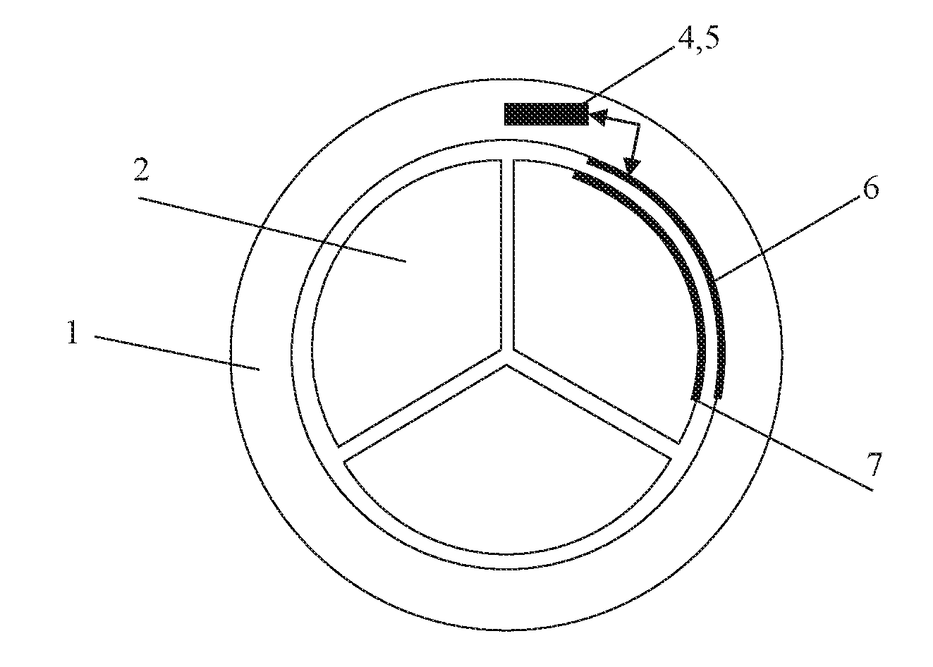
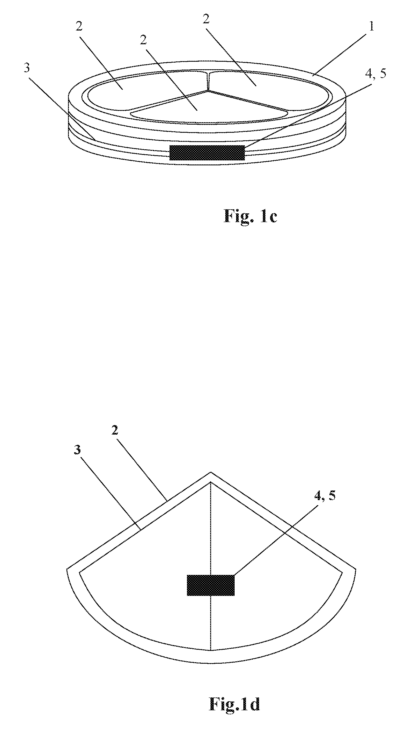
[0020] FIG. 1c is a perspective view of placement of an antenna as a closed-loop multi-turn wiring around the entire housing.
[0021] FIG. 1d is a perspective view of placement of an antenna as a closed-loop multi-turn wiring in a leaflet of the heart valve.
[0022] FIG. 2a is a top plan view of placement of inductor coils in the housing and in the oppositely situated leaflet.
[0023] FIG. 2b is a top plan view of placement of inductor coils along the opposite edges in the leaflets.
[0024] FIG. 2c is a top plan view of placement of inductor coils in the housing along all the edges in the leaflets.
[0025] FIG. 3a-1 is a top plan view of an example of placement of an emission sensor in the leaflet.
[0026] FIG. 3a-2 is a side view; wherein the leaflet is in a closed position, the emission sensor in the leaflet is emitting aside from the housing.
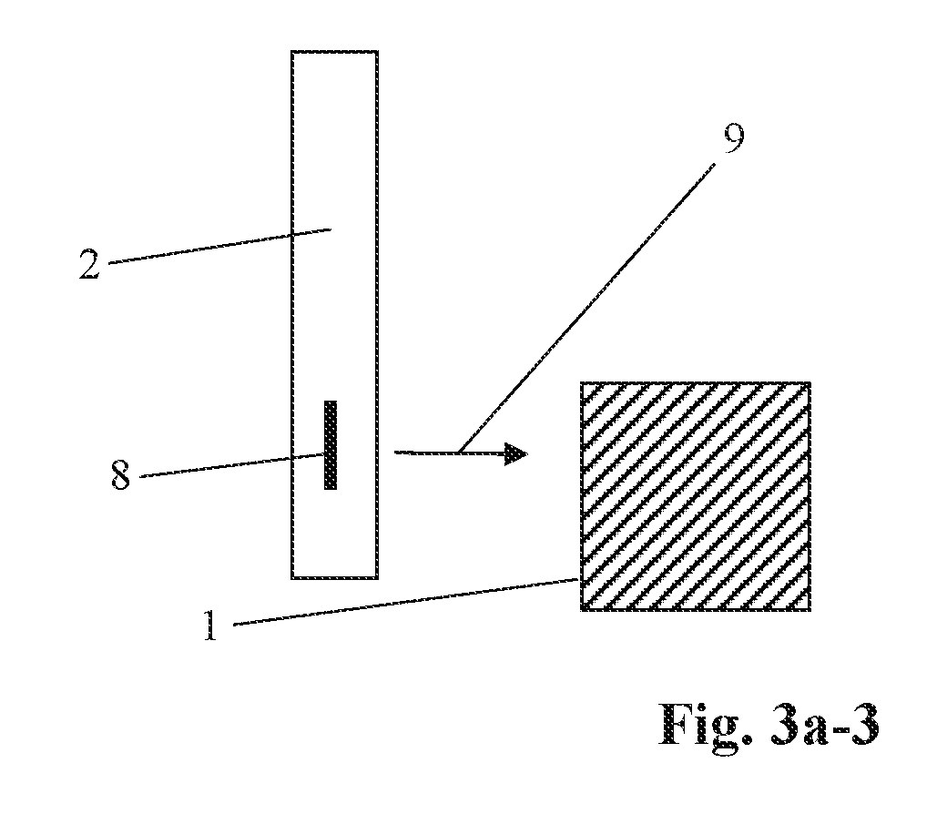
[0027] FIG. 3a-3 is a side view; wherein the leaflet is in an open position, the emission sensor in the leaflet is emitting towards the housing.
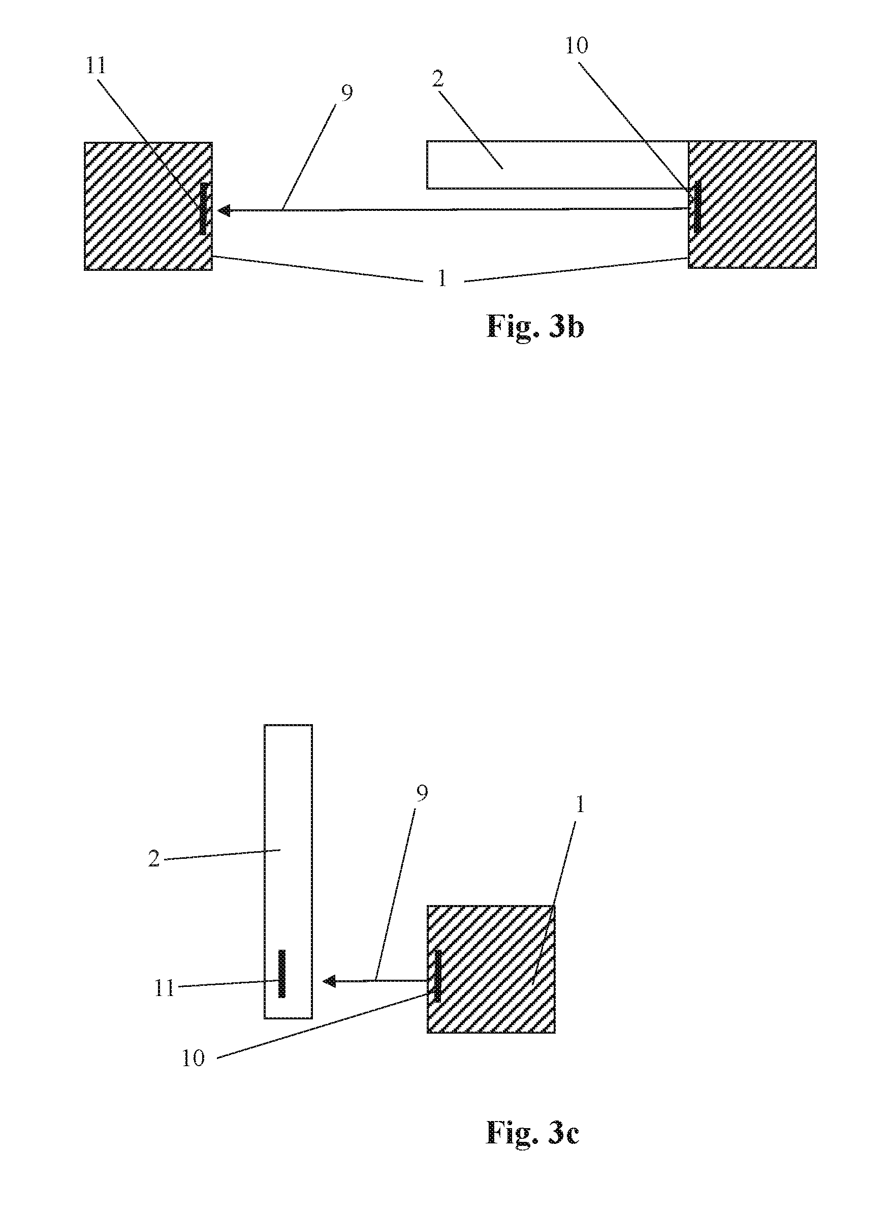
[0028] FIG. 3b is a side view; the leaflet is in a closed position, wherein the emission sensor in the right side of the housing (transmitter) is emitting towards the sensor (receiver) in the left part of the housing without interference.
[0029] FIG. 3c is a side view; wherein the leaflet is in an open position, the emission of the sensor in the right side of the housing (transmitter) reaches the sensor (receiver) in the leaflet.
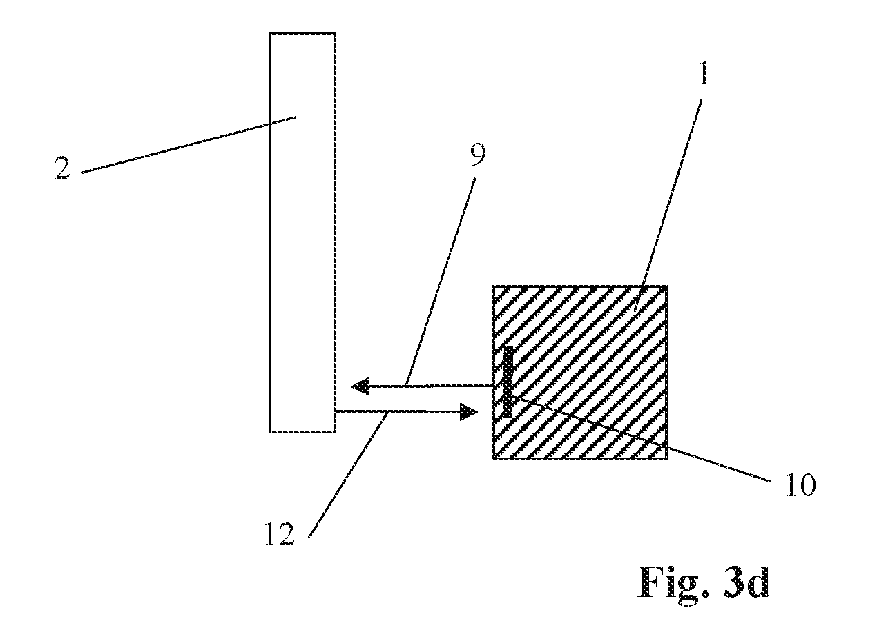
[0030] FIG. 3d is a side view; the leaflet is in an open position, wherein the emission of the sensor in the right side of the housing (transmitter) is reflected from the leaflet and returns to the sensor (receiver) in the right side of the housing.
DETAILED DESCRIPTION OF THE INVENTION
[0031] While the invention may be susceptible to embodiment in different forms, there are described in detail herein below, specific embodiments of the present invention, with the understanding that the instant disclosure is to be considered an exemplification of the principles of the invention, and is not intended to limit the invention to that as described herein.
[0032] According to preferred embodiments of the disclosed invention, the prosthetic heart valve comprises a housing 1, at least one leaflet 2 installed within the housing and a number of valve performance monitoring devices (monitoring devices 5) with a number of additional active or passive sensors 4 equipped with wireless electrical power supply and wireless data transmission devices (with their own antennas 3--common or separate/independent); all the devices are integrated (built-in) into the housing' s body, and/or into the leaflet's body, and/or other parts of the valve. The housing's and its leaflets' volumetric dimensions allow deploying therein a certain number of diagnostic testers, while their linear dimensions allow deploying therein various types of antennas both for a remote power supply and for an informational exchange with an external device.
[0033] The substance of the invention is explained by the drawings related to the tri-leaflet prosthetic heart valve (further named `valve`). The sensors 4 and the monitoring devices 5 may be built into the housing 1 (preferably of an annular shape) or in the leaflet 2 depicted in FIGS. 1a-1, 1a-2, 1a-3, 1b, 1c, 1d and FIGS. 3a-1, 3a-2, 3a-3, 3b, 3c, 3d. The sensors 4 and/or the monitoring devices 5 are equipped with the antennas 3.
[0034] Examples of placement of the antennas 3 of the sensors 4 and the monitoring devices 5 in the housing 1 and the leaflets 2 are shown in FIGS. 1a-1, 1a-2, 1a-3, 1b, 1c (for the housing 1) and in FIG. 1d (for the leaflet 2). FIGS. 1a-1, 1a-2, 1a-3 demonstrate the placement of various types of the antenna 3 in one of the housing's sectors.
[0035] To enhance efficacy of the antenna 3 by enlarging/expanding its dimensions, the antenna 3 may be deployed along the full circumference of the housing 1 (shown in FIG. 1b) as a single closed-loop or open circuit wiring turn. To further enhance the antenna's capability, it may be configured as a multi-turn loop (FIG. 1c). A rather large area of the surface of the leaflets 2 and a long perimeter of each leaflet 2 allow for placement of the antenna 3 directly in the leaflet 2. One of the possible variants is shown in FIG. 1d.
[0036] The housing 1 and/or each leaflet 2 may be equipped with an oscillating circuit including an inductor coil 6 or 7 and a capacitor (not shown) connected to the monitoring device 5 and/or the sensor 4. By assessing inductive interconnection between the inductor coils 6 or 7 at the moment of opening/closing the leaflets 2, it is possible to determine a degree of opening and closing of the leaflets 2 and timing characteristics of operation of the valve.
[0037] FIGS. 2 (2a, 2b, 2c) show possible options of placement of the inductor coils 6 and 7 to determine the degree of opening/closing the leaflets 2 (2a--placement of the inductor coils 6 in the housing 1 and opposite to the inductor coils 7 disposed in the opposite situated leaflet 2; 2b--placement of the inductor coils 7 along the opposite edges in the leaflets 2; 2c--placement of the inductor coils 6 and 7 in the housing 1, in the opposite situated leaflet 2 and along the opposite edges in the leaflets 2).
[0038] During the opening of the leaflets, the distances between the inductor coils 6 and 7 both in the leaflets 2, and between the leaflets 2 and the housing 1, are growing, thereby minimizing inductive interconnection between the circuits; while when the leaflets 2 are completely closed the interconnection between the circuits is maximal. Accordingly, the monitoring device 5 assesses the circuits' interconnection and provides for determination of a degree of opening and closing the leaflet.
[0039] Calibration of measurements may be effected prior to implantation of the valve, if necessary. The calibration may also be effected immediately after the implantation, to evaluate corrections related to nonzero physical parameters of body/blood and their influence on the interconnection between the circuits.
[0040] In another preferred embodiment, additional sensors 4 may be integrated into the housing 1 or into the leaflet 2, which may be both self-sufficient and may work independently from the monitoring device 5 (all necessary electronic circuits/components can be arranged inside the body of the sensor 4); or, optionally, the additional sensors 4 may be connected with the monitoring device 5, which allows determining not only a degree of opening of the leaflets 2 and timing characteristics of performance of the valve, but also a number of additional parameters, e.g. blood temperature and viscosity, mechanical and physical parameters of the valve's housing and leaflets, etc.
[0041] FIGS. 3a-1, 3a-2, 3a-3, 3b, 3c, 3d show possible locations of emission sensors 8 (in the leaflet, in an emission/transmission mode), emission sensors 10 (in the housing 1) and emission sensors 11 (receivers, transmitters or transceivers) for determination of a degree of opening the leaflets and for determination of physical/chemical characteristics of the blood circulatory system.
[0042] The emission sensors 8, 10 and 11 may be both electro-mechanical e.g. based on piezo electrical elements as well as electrical e.g. based on light emitting diodes (LEDs)/receiving photodiodes of various wave length ranges including monochrome emitters (lasers) and others.
[0043] Examples of placement of the emission sensor 8 in the leaflet 2 and their operation modes are shown in FIGS. 3a-1, 3a-2, 3a-3. When the leaflet 2 is in a closed position, the sensor 8 (its transmitting part), disposed in the leaflet 2, emits into a patient's body aside from the valve housing 1, a reflected beam is absent.
[0044] When the leaflet 2 is fully open, an emitted beam 9 reaches the housing 1, and then is either reflected from the housing 1 and can be detected by a receiving part of the sensor 8 in the leaflet 2, or is detected by a separate receiver in the housing 1.
[0045] Another example of placement of the emission sensors 10 (transmitting part of the transceiver) and emission sensors 11 (receiving part) in the housing 1 is shown in FIG. 3b. The emission sensor (transmitting part of the transceiver) 10 is disposed in one side of the housing 1; when the leaflet 2 is in a closed position, the emitted beam 9 can be detected on the opposite side of the housing 1 by the emission sensor (receiver) 11; when the leaflet 2 is fully open, the emitted beam 9 can be detected by the emission sensors 11 (receiving part) in the leaflet 2 (FIG. 3c), or a reflected beam 12 can be detected by the receiving part of the emission sensor (transceiver) 10 contained in the housing 1 (FIG. 3d).
[0046] An ultrasonic electromechanical emitter, disposed within the valve, may also carry out the function of valve cleaning from blood clots or preventing such clots formation. The ultrasonic emitter can be deployed inside all parts of the valve: in the housing 1 and/or in each leaflet 2. The regular use of the emitter will prevent the blood clots agglomeration along the valve's elements, a probable thrombosis or a deviation of the valve operation from the normal mode in the future.
[0047] A temperature sensor will allow monitoring a patient's blood temperature. Placement of such temperature sensors and the ultrasonic cleaning emitter does not require illustration being a designer's choice.
[0048] The presented drawings do not illustrate the placement of sensors and emitters within a bi-leaflet valve and a single leaflet valve. Their configuration and functioning will be understood by those skilled in the art from analogy with the above description for the tri-leaflet valve.
* * * * *
D00000
D00001
D00002
D00003
D00004
D00005
D00006
D00007
XML
uspto.report is an independent third-party trademark research tool that is not affiliated, endorsed, or sponsored by the United States Patent and Trademark Office (USPTO) or any other governmental organization. The information provided by uspto.report is based on publicly available data at the time of writing and is intended for informational purposes only.
While we strive to provide accurate and up-to-date information, we do not guarantee the accuracy, completeness, reliability, or suitability of the information displayed on this site. The use of this site is at your own risk. Any reliance you place on such information is therefore strictly at your own risk.
All official trademark data, including owner information, should be verified by visiting the official USPTO website at www.uspto.gov. This site is not intended to replace professional legal advice and should not be used as a substitute for consulting with a legal professional who is knowledgeable about trademark law.