Surgical Clip Applier
Baril; Jacob C. ; et al.
U.S. patent application number 16/262073 was filed with the patent office on 2019-10-31 for surgical clip applier. The applicant listed for this patent is Covidien LP. Invention is credited to Jacob C. Baril, Matthew A. Dinino, Roy J. Pilletere, Justin Thomas.
| Application Number | 20190328389 16/262073 |
| Document ID | / |
| Family ID | 66286138 |
| Filed Date | 2019-10-31 |


| United States Patent Application | 20190328389 |
| Kind Code | A1 |
| Baril; Jacob C. ; et al. | October 31, 2019 |
SURGICAL CLIP APPLIER
Abstract
A surgical clip applier includes a handle assembly and an elongated assembly configured to releasably engage the handle assembly. The handle assembly includes a trigger and a drive bar wherein pivoting of the trigger through a full actuation stroke translates the drive bar through a full drive distance. The drive bar has a magnetic distal end portion. The elongated assembly includes an inner drive assembly including a magnetic proximal end portion. Upon engagement of the elongated assembly with the handle assembly, the magnetic proximal end portion of the inner drive assembly is configured to attract the magnetic distal end portion of the drive bar to move the drive bar and pivot the trigger such that the trigger is pivotable through a reduced actuation stroke to translate the drive bar through a reduced drive distance.
| Inventors: | Baril; Jacob C.; (Norwalk, CT) ; Pilletere; Roy J.; (North Haven, CT) ; Thomas; Justin; (New Haven, CT) ; Dinino; Matthew A.; (Newington, CT) | ||||||||||
| Applicant: |
|
||||||||||
|---|---|---|---|---|---|---|---|---|---|---|---|
| Family ID: | 66286138 | ||||||||||
| Appl. No.: | 16/262073 | ||||||||||
| Filed: | January 30, 2019 |
Related U.S. Patent Documents
| Application Number | Filing Date | Patent Number | ||
|---|---|---|---|---|
| 62662284 | Apr 25, 2018 | |||
| Current U.S. Class: | 1/1 |
| Current CPC Class: | A61B 17/1285 20130101; A61B 2017/2902 20130101; A61B 17/083 20130101; A61B 17/10 20130101; A61B 2017/0042 20130101; A61B 2017/0046 20130101; A61B 2017/00477 20130101; A61B 2017/00876 20130101; A61B 17/00234 20130101; A61B 17/29 20130101; A61B 2017/00367 20130101 |
| International Class: | A61B 17/10 20060101 A61B017/10; A61B 17/08 20060101 A61B017/08; A61B 17/00 20060101 A61B017/00 |
Claims
1. A surgical clip applier, comprising: a handle assembly, including: a housing; a trigger pivotably coupled to the housing and pivotable relative thereto through a full actuation stroke from a first un-actuated position of the trigger to an actuated position of the trigger; and a drive bar operably coupled to the trigger such that pivoting of the trigger through the full actuation stroke translates the drive bar through the housing a full drive distance from a first un-actuated position of the drive bar to an actuated position of the drive bar, the drive bar including a magnetic distal end portion; and an elongated assembly configured to releasably engage the handle assembly, the elongated assembly including: a proximal hub; an elongated shaft extending distally from the proximal hub; an end effector assembly supported at a distal end portion of the elongated shaft, the end effector assembly including first and second jaw members; and an inner drive assembly extending through the proximal hub and the elongated shaft, the inner drive assembly operably coupled to the end effector assembly such that translation of the inner drive assembly though the proximal hub and the elongated shaft moves the first and second jaw members from an open position to a closed position, the inner drive assembly including a magnetic proximal end portion, wherein, upon engagement of the elongated assembly with the handle assembly, the magnetic proximal end portion of the inner drive assembly is configured to attract the magnetic distal end portion of the drive bar to move the drive bar to and retain the drive bar in a second un-actuated position of the drive bar wherein the drive bar is movable a reduced drive distance from the second un-actuated position of the drive bar to the actuated position of the drive bar, thereby pivoting the trigger and retaining the trigger in a second un-actuated position of the trigger wherein the trigger is pivotable through a reduced actuation stroke from the second un-actuated position of the trigger to the actuated position of the trigger.
2. The surgical clip applier according to claim 1, wherein with the elongated assembly engaged with the handle assembly, the trigger is movable through the reduced actuation stroke to thereby translate the drive bar through the reduced drive distance to, in turn, translate the inner drive assembly though the proximal hub and the elongated shaft to move the first and second jaw members from the open position to the closed position.
3. The surgical clip applier according to claim 2, wherein the first and second jaw members are configured to retain a surgical clip therebetween such that, upon movement of the first and second jaw members from the open position to the closed position, the surgical clip is formed.
4. The surgical clip applier according to claim 1, wherein the handle assembly further includes a linkage assembly including at least one link coupling the trigger and the drive bar with one another such that pivoting of the trigger translates the drive bar.
5. The surgical clip applier according to claim 1, wherein the inner drive assembly includes at least one actuation shaft.
6. The surgical clip applier according to claim 1, wherein the handle assembly further includes a latch mechanism configured to releasably engage the proximal hub of the elongated assembly with the housing of the handle assembly.
7. A surgical instrument, comprising: a handle assembly including a housing, a trigger pivotably coupled to the housing, and a drive bar slidably disposed within the housing, the trigger pivotable relative to the housing through a full actuation stroke from a first un-actuated position of the trigger to an actuated position of the trigger to translate the drive bar through the housing through a full drive distance from a first un-actuated position of the drive bar to an actuated position of the drive bar, the drive bar including a magnetic distal end portion; an elongated assembly configured to releasably engage the handle assembly, the elongated assembly including a proximal hub, an elongated shaft extending distally from the proximal hub, an end effector assembly supported at a distal end portion of the elongated shaft, and an inner drive assembly operably coupled to the end effector assembly such that translation of the inner drive assembly actuates the end effector assembly, the inner drive assembly including a magnetic proximal end portion, wherein, upon engagement of the elongated assembly with the handle assembly, the magnetic proximal end portion of the inner drive assembly attracts the magnetic distal end portion of the drive bar to pull the drive bar to a second un-actuated position of the drive bar and pivot the trigger to a second un-actuated position of the trigger such that the trigger is pivotable relative to the housing through a reduced actuation stroke from the second un-actuated position of the trigger to the actuated position of the trigger to translate the drive bar through the housing through a reduced drive distance from the second un-actuated position of the drive bar to the actuated position of the drive bar.
8. The surgical instrument according to claim 7, wherein with the elongated assembly engaged with the handle assembly, the trigger is movable through the reduced actuation stroke to thereby translate the drive bar through the reduced drive distance to, in turn, translate the inner drive assembly though the proximal hub and the elongated shaft to actuate the end effector assembly.
9. The surgical instrument according to claim 8, wherein the end effector assembly includes first and second jaw members configured to retain a surgical clip therebetween such that, upon actuation of the end effector assembly, the first and second jaw members are closed position to form the surgical clip.
10. The surgical instrument according to claim 8, wherein the handle assembly further includes a linkage assembly including at least one link coupling the trigger and the drive bar with one another such that pivoting of the trigger translates the drive bar.
11. The surgical instrument according to claim 8, wherein the inner drive assembly includes at least one actuation shaft.
12. The surgical instrument according to claim 1, wherein the handle assembly further includes a latch mechanism configured to releasably engage the proximal hub of the elongated assembly with the housing of the handle assembly.
Description
CROSS-REFERENCE TO RELATED APPLICATION
[0001] This application claims the benefit of and priority to U.S. Provisional Patent Application No. 62/662,284 filed Apr. 25, 2018, the entire disclosure of which is incorporated by reference herein.
BACKGROUND
Technical Field
[0002] The present disclosure relates to surgical instruments. More particularly, the present disclosure relates to surgical clip appliers configured to apply surgical clips to tissue.
Description of Related Art
[0003] Surgical clip appliers are known in the art and are used for a number of distinct and useful surgical procedures. In the case of a laparoscopic surgical procedure, access to the interior of an abdomen is achieved through narrow tubes or cannulas inserted through a small entrance incision in the skin. Minimally invasive procedures performed elsewhere in the body are often generally referred to as endoscopic procedures.
[0004] Endoscopic surgical clip appliers having various sizes (e.g., diameters), that are configured to apply a variety of diverse surgical clips, are also known in the art, and are capable of applying a single or multiple surgical clips during an entry to the body cavity. Such surgical clips are typically fabricated from a biocompatible material and are usually compressed over tissue. Once applied to tissue, the compressed surgical clip terminates the flow of fluid therethrough.
SUMMARY
[0005] As detailed herein and shown in the drawing figures, as is traditional when referring to relative positioning on a surgical instrument, the term "proximal" refers to the end of the apparatus or component thereof which is closer to the user and the term "distal" refers to the end of the apparatus or component thereof which is further away from the user. Further, to the extent consistent, any or all of the aspects and features detailed herein may be used in conjunction with any or all of the other aspects and features detailed herein.
[0006] Provided in accordance with aspects of the present disclosure is a surgical clip applier including a handle assembly and an elongated assembly configured to releasably engage the handle assembly.
[0007] The handle assembly includes a housing, a trigger pivotably coupled to the housing, and a drive bar disposed within the housing and operably coupled to the trigger. The trigger is pivotable through a full actuation stroke from a first un-actuated position of the trigger to an actuated position of the trigger. The drive bar is translatable, in response to pivoting of the trigger, a full drive distance from a first un-actuated position of the drive bar to an actuated position of the drive bar. The drive bar includes a magnetic distal end portion.
[0008] The elongated assembly includes a proximal hub, an elongated shaft extending distally from the proximal hub, an end effector assembly supported at a distal end portion of the elongated shaft and including first and second jaw members, and an inner drive assembly extending through the proximal hub and the elongated shaft. The inner drive assembly is operably coupled to the end effector assembly such that translation of the inner drive assembly though the proximal hub and the elongated shaft moves the first and second jaw members from an open position to a closed position. The inner drive assembly includes a magnetic proximal end portion.
[0009] Upon engagement of the elongated assembly with the handle assembly, the magnetic proximal end portion of the inner drive assembly is configured to attract the magnetic distal end portion of the drive bar to move the drive bar to and retain the drive bar in a second un-actuated position of the drive bar wherein the drive bar is movable a reduced drive distance from the second un-actuated position of the drive bar to the actuated position of the drive bar. The movement and retention of the drive bar in the second un-actuated position pivots the trigger to and retains the trigger in a second un-actuated position of the trigger wherein the trigger is pivotable through a reduced actuation stroke from the second un-actuated position of the trigger to the actuated position of the trigger.
[0010] In an aspect of the present disclosure, with the elongated assembly engaged with the handle assembly, the trigger is movable through the reduced actuation stroke to thereby translate the drive bar through the reduced drive distance to, in turn, translate the inner drive assembly though the proximal hub and the elongated shaft to move the first and second jaw members from the open position to the closed position.
[0011] In another aspect of the present disclosure, the first and second jaw members are configured to retain a surgical clip therebetween such that, upon movement of the first and second jaw members from the open position to the closed position, the surgical clip is formed.
[0012] In still another aspect of the present disclosure, the handle assembly further includes a linkage assembly including at least one link coupling the trigger and the drive bar with one another such that pivoting of the trigger translates the drive bar.
[0013] In yet another aspect of the present disclosure, the inner drive assembly includes at least one actuation shaft.
[0014] In still yet another aspect of the present disclosure, the handle assembly further includes a latch mechanism configured to releasably engage the proximal hub of the elongated assembly with the housing of the handle assembly.
[0015] A surgical instrument provided in accordance with aspects of the present disclosure includes a handle assembly and an elongated assembly configured to releasably engage the handle assembly.
[0016] The handle assembly includes a housing, a trigger pivotably coupled to the housing, and a drive bar slidably disposed within the housing. The trigger is pivotable relative to the housing through a full actuation stroke from a first un-actuated position of the trigger to an actuated position of the trigger to translate the drive bar through the housing through a full drive distance from a first un-actuated position of the drive bar to an actuated position of the drive bar. The drive bar includes a magnetic distal end portion.
[0017] The elongated assembly includes a proximal hub, an elongated shaft extending distally from the proximal hub, an end effector assembly supported at a distal end portion of the elongated shaft, and an inner drive assembly operably coupled to the end effector assembly such that translation of the inner drive assembly actuates the end effector assembly. The inner drive assembly includes a magnetic proximal end portion,
[0018] Upon engagement of the elongated assembly with the handle assembly, the magnetic proximal end portion of the inner drive assembly attracts the magnetic distal end portion of the drive bar to pull the drive bar to a second un-actuated position of the drive bar and pivot the trigger to a second un-actuated position of the trigger. As such, the trigger is thereafter pivotable relative to the housing through a reduced actuation stroke from the second un-actuated position of the trigger to the actuated position of the trigger to translate the drive bar through the housing through a reduced drive distance from the second un-actuated position of the drive bar to the actuated position of the drive bar.
[0019] In an aspect of the present disclosure, with the elongated assembly engaged with the handle assembly, the trigger is movable through the reduced actuation stroke to thereby translate the drive bar through the reduced drive distance to, in turn, translate the inner drive assembly though the proximal hub and the elongated shaft to actuate the end effector assembly.
[0020] In another aspect of the present disclosure, actuating the end effector assembly includes moving the first and second jaw members of the end effector assembly to a closed position to form a surgical clip disposed therebetween.
[0021] In still another aspect of the present disclosure, the handle assembly further includes a linkage assembly including at least one link coupling the trigger and the drive bar with one another such that pivoting of the trigger translates the drive bar.
[0022] In yet another aspect of the present disclosure, the inner drive assembly includes at least one actuation shaft.
[0023] In still yet another aspect of the present disclosure, the handle assembly further includes a latch mechanism configured to releasably engage the proximal hub of the elongated assembly with the housing of the handle assembly.
BRIEF DESCRIPTION OF THE DRAWINGS
[0024] Aspects and features of the present disclosure are described in detail with reference to the drawing figures wherein like reference numerals identify similar or identical structural elements and:
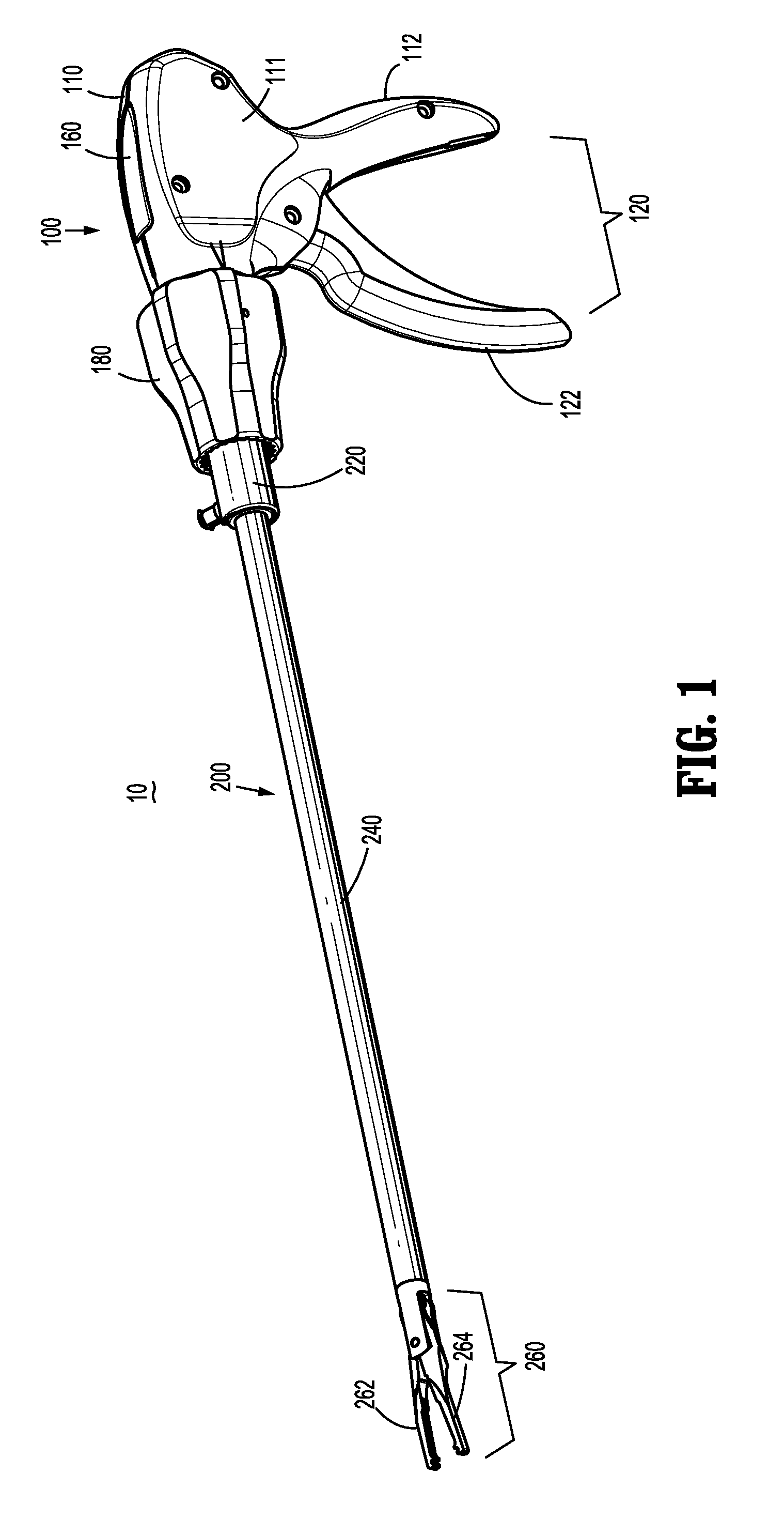
[0025] FIG. 1 is a perspective view of a surgical clip applier provided in accordance with the present disclosure including a handle assembly having an elongated assembly engaged therewith;
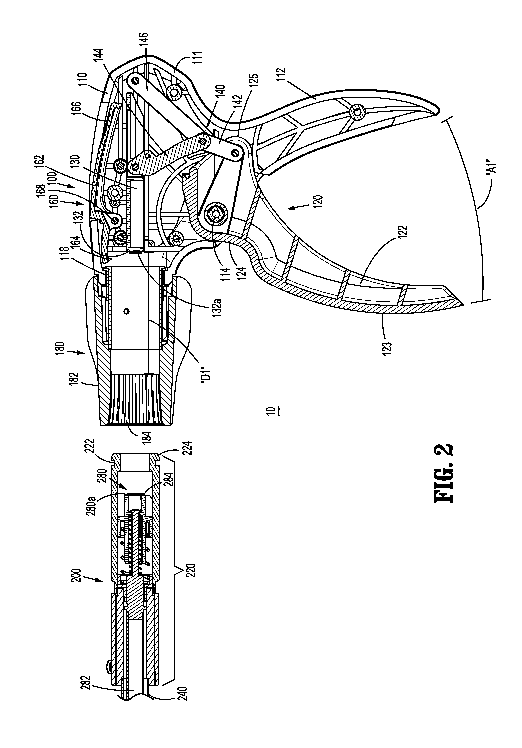
[0026] FIG. 2 is an enlarged, longitudinal, cross-sectional view of a proximal portion of the surgical clip applier of FIG. 1 with the elongated assembly disengaged engaged from the handle assembly;
[0027] FIG. 3 is an enlarged, longitudinal, cross-sectional view of the proximal portion of the surgical clip applier of FIG. 2 with the elongated assembly moving into engagement with the handle assembly; and
[0028] FIG. 4 is an enlarged, longitudinal, cross-sectional view of the proximal portion of the surgical clip applier of FIG. 2 with the elongated assembly fully engaged with the handle assembly.
DETAILED DESCRIPTION
[0029] Turning to FIGS. 1-4, a surgical clip applier embodying the aspects and features of the present disclosure is shown identified by reference numeral 10. Surgical clip applier 10 generally includes a handle assembly 100 and one or more elongated assemblies, e.g., elongated assembly 200, selectively connectable to handle assembly 100. Handle assembly 100 is configured to operate an elongated assembly upon connection thereto, and may be configured as a sterilizable, reusable component or otherwise configured such that handle assembly 100 may be used with different and/or additional elongated assemblies during the course of one or more surgical procedures. The one or more elongated assemblies may be configured as single-use disposable component, limited-use disposable component, or reusable component, depending upon a particular purpose. For the purposes herein, elongated assembly 200 is described, although it is understood that handle assembly 100 is configured for use with additional and/or alternative elongated assemblies.
[0030] Handle assembly 100 generally includes a housing 110, an actuation mechanism 120 operably associated with housing 110, a latch assembly 160 operably associated with housing 110, and a rotating receiver assembly 180 operably coupled to a distal portion of housing 110. Housing 110 of handle assembly 100 supports and/or encloses the operating components of handle assembly 100 and defines a body portion 111 and a fixed handle portion 112 depending from body portion 111. Body portion 111 of housing 110 includes an internal pivot post 114 extending transversely within body portion 111 and a distal opening 118 through which a proximal end portion of elongated assembly 200 extends when elongated assembly 200 is engaged with handle assembly 100.
[0031] Actuation mechanism 120 is operably supported by housing 110 and includes a trigger 122, a drive bar 130, and a linkage assembly 140. Trigger 122 includes a grasping portion 123, an intermediate pivot portion 124, and a proximal extension 125. Grasping portion 123 of trigger 122 extends downwardly from body portion 111 of housing 110 in opposed relation relative to fixed handle portion 112 of housing 110. Grasping portion 123 is configured to facilitate grasping and manipulation of trigger 122. Intermediate pivot portion 124 of trigger 122 is at least partially disposed within housing 110 and defines a pivot aperture 126 that is configured to receive pivot post 114 of housing 110 so as to enable pivoting of trigger 122 about pivot post 114 and relative to housing 110, e.g., between an un-actuated position, wherein grasping portion 123 of trigger 122 is spaced-apart relative to fixed handle portion 112, and an actuated position, wherein grasping portion 123 of trigger 122 is approximated relative to fixed handle portion 112.
[0032] Proximal extension 125 of trigger 122 is disposed on an opposite side of intermediate pivot portion 124 and, thus, pivot post 114, as compared to grasping portion 123 of trigger 122. As such, pivoting of grasping portion 123 to rotate in one direction, e.g., proximally towards fixed handle portion 112, pivots proximal extension 125 to rotate in the opposite direction, e.g., distally.
[0033] Linkage assembly 140 includes a first linkage 142, a second linkage 144, and a third linkage 146. First linkage 142 is pivotably coupled to proximal extension 125 of trigger 122 towards a first end portion of first linkage 142. Second and third linkages 144, 146, respectively, are each pivotably coupled to a second, opposite end portion of first linkage 142 at respective first end portions of second and third linkages 144, 146. A second, opposite end portion of second linkage 144 is pivotably coupled to drive bar 130, while a second, opposite end portion of third linkage 146 is pivotably coupled to body portion 111 of housing 110. Thus, the pivot point between first linkage 142 and proximal extension 125 of trigger 122, the pivot point between first linkage 142 and second and third linkages 144, 146, respectively, and the pivot point between second linkage 144 and drive bar 130 are movable pivot points (e.g., movable relative to housing 110), while the pivot point between third linkage 146 and housing 110 is a fixed pivot point (e.g., fixed relative to housing 110).
[0034] Upon actuation of trigger 122, e.g., proximal pivoting of grasping portion 123 of trigger 122 in a counterclockwise direction from the orientation illustrated in FIGS. 1-4, proximal extension 125 is moved in a distal, counterclockwise direction, thereby urging first linkage 142 towards drive bar 130. This movement of first linkage 142 towards drive bar 130, in turn, urges the first end portions of second and third linkages 144, 146, respectively, towards drive bar 130 to, in turn, urge the second end portion of second linkage 144 distally such that drive bar 130 is translated distally through body portion 111 of housing 110 from a proximal, un-actuated position thereof towards a distal, actuated position thereof. A biasing spring (not shown) may be provided to bias trigger 122 in a clockwise direction towards the un-actuated position thereof, thereby biasing drive bar 130 proximally towards its un-actuated position. Trigger 122 defines a maximum actuation stroke "A2" from its un-actuated position to its actuated position to, in turn, translate drive bar 130 a maximum drive distance "D1" from its un-actuated position to its actuated position.
[0035] Drive bar 130 is slidably disposed within body portion 111 of housing 110. At least a distal portion 132 of drive bar 130 includes a magnetic material 132a. A distal end portion 132 of drive bar 130 may be formed from a magnetic material, include a magnetic material coated thereon, may engage a magnet thereon or therein, or may otherwise be configured such that distal end portion 132 of drive bar 130 is magnetic.
[0036] Latch assembly 160 is configured to facilitate releasable locking engagement of elongated assembly 200 with handle assembly 100. Latch assembly 160, more specifically, includes a pivoting lever arm 162 operably disposed on and extending into body portion 111 of housing 110. Lever arm 162 includes an engagement finger 164 disposed towards one end thereof and a manipulatable portion 166 disposed towards the other end thereof with a pivot portion 168 disposed therebetween. Thus, upon depression of manipulatable portion 166 into housing 110 from a locked position to an unlocked position, engagement finger 164 is withdrawn upwardly and, upon release of manipulatable portion 166 and return thereof to the locked position, engagement finger 164 is returned downwardly. A torsion spring (not shown) disposed about pivot portion 168, or other suitable biasing spring in any suitable position, may be provided to bias lever arm 162 towards the locked position, although other configurations are also contemplated.
[0037] Rotating receiver assembly 180 is configured to receive a proximal end portion of elongated assembly 200 and to enable selective rotation thereof relative to housing 110. Rotating receiver assembly 180 includes a rotation knob 182 rotatably coupled to body portion 111 of housing 110 and extending distally therefrom. Rotation knob 182 defines a lumen 184 extending therethrough in communication with distal opening 118 of body portion 111 of housing 110 to enable insertion of a proximal portion of elongated assembly 200 therethrough and into operable engagement within housing 110.
[0038] Elongated assembly 200 generally includes a proximal hub 220, an elongated shaft 240 extending distally from proximal hub 220, an end effector assembly 260 disposed towards a distal end portion of elongated shaft 240, and an inner drive assembly 280 extending through proximal hub 220 and elongated shaft 240 and configured for operable coupling between handle assembly 100 and end effector assembly 260 when elongated assembly 200 is engaged with handle assembly 100 to enable firing of a surgical clip (not shown) about tissue.
[0039] Proximal hub 220 is configured for insertion through lumen 184 of rotation knob 182 and into body portion 111 of housing 110. Proximal hub 220 defines an annular recess 222 towards the proximal end thereof and a chamfered proximal edge 224. Thus, upon insertion of proximal hub 220 through lumen 184 of rotation knob 182 and into body portion 111 of housing 110, chamfered proximal edge 224 cams engagement finger 164 of latch assembly 160 over the outer surface of proximal hub 220 until engagement finger 164 is disposed in alignment with annular recess 222, wherein engagement finger 164 falls into engagement within annular recess 222 to engage proximal hub 220 and, thus, elongated assembly 200, with handle assembly 100. In order to disengage and remove elongated assembly 200 from handle assembly 100, manipulatable portion 166 of latch assembly 160 is depressed into housing 110 to withdraw engagement finger 164 from annular recess 222 and enable elongated assembly 200 to be pulled distally and removed from handle assembly 100. Proximal hub 220 and/or rotation knob 182 may further include complimentary keying features such that, upon insertion of proximal hub 220 into rotation knob 182, elongated assembly 200 is rotationally fixed relative to rotation knob 182 and such that rotation knob 182 and elongated assembly 200 are together rotatable relative to housing 110 upon rotation of rotation knob 182 relative to housing 110. Elongated shaft 240 extends distally from proximal hub 220 and supports end effector assembly 260 towards the distal end thereof.
[0040] End effector assembly 260 includes first and second jaw members 262, 264 pivotably engaged to one another to permit pivoting of jaw members 262, 264 relative to one another and elongated shaft 240 between an open position and a closed position. Jaw members 262, 264 are configured to receive and close, fire, or form a surgical clip about tissue, e.g., a surgical clip similar to those shown and described in U.S. Pat. No. 4,834,096, then entire contents of which are hereby incorporated herein by reference. However, it is contemplated that any suitable end effector assembly configured to close, fire, or form any suitable surgical clip(s) may be utilized with elongated assembly 200 in accordance with the present disclosure.
[0041] Inner drive assembly 280, as noted above, extends through proximal hub 220 and elongated shaft 240. Inner drive assembly 280 may include one or more actuation shafts 282 that cooperate to operably couple to jaw members 262, 264 of end effector assembly 260 towards a distal end portion (not shown) of inner drive assembly 280 such that translation, e.g., distal translation, of the one or more actuation shafts 282 of inner drive assembly 280 through elongated shaft 240 and relative to end effector assembly 260 pivots jaw members 262, 264 from the open position towards the closed position. A proximal end portion 284 of inner drive assembly 280, e.g., the proximal portion of one of the actuation shafts 282, is configured to couple to distal portion 132 of drive bar 130 upon engagement of elongated assembly 200 within handle assembly 100.
[0042] Proximal end portion 284 of inner drive assembly 280 includes a magnetic material 280a. Proximal end portion 284, more specifically, may be formed from a magnetic material, include a magnetic material coated thereon, may engage a magnet thereon or therein, or may otherwise be configured such that proximal end potion 284 of inner drive assembly 280 is magnetic.
[0043] Upon engagement of elongated assembly 200 within handle assembly 100, the magnetic distal end portion 132 of drive bar 130 and the magnetic proximal end portion 284 of inner drive assembly 280 attract and couple to one another in abutting, inter-fitting, or other suitable engagement to secure distal end portion 132 of drive bar 130 and proximal end portion 284 of inner drive assembly 280 relative to one another. As such, distal translation of drive bar 130 relative to housing 110, e.g., in response to actuation of trigger 122, urges inner drive assembly 280 distally through elongated shaft 240 and relative to end effector assembly 260 to pivot jaw members 262, 264 towards the closed position to close, fire, or form a surgical clip disposed between jaw members 262, 264. On the other hand, proximal translation of drive bar 130 relative to housing 110, in response to release or return of trigger 122, pulls inner drive assembly 280 proximally through elongated shaft 240 and relative to end effector assembly 260 to pivot jaw members 262, 264 back towards the open position.
[0044] Referring generally to FIGS. 1-4, as noted above, handle assembly 100 is configured such that trigger 122 defines maximum actuation stroke "A1" that, in turn, translates drive bar 130 maximum drive distance "D1." Inner drive assembly 280, as also noted above, is configured to translate through elongated shaft 240 and relative to end effector assembly 260 to pivot jaw members 262, 264 from the open position towards the closed position to close, fire, or form a surgical clip disposed between jaw members 262, 264. However, depending upon the configuration of the elongated assembly 200 utilized and/or the surgical clip (not shown) to be closed, fired, or formed, drive bar 130 may not need to translate the maximum drive distance "D1" in order to fully actuate the inner drive assembly 280 to fully close, fire, or form the surgical clip. In such instances where drive bar 130 is not required to translate the maximum drive distance "D1" in order to fully actuate inner drive assembly 280, a dead space may be created at the beginning and/or end of the maximum actuation stroke "A1" of trigger 122 (and, thus, the maximum drive distance "D1" of drive bar 130) wherein trigger 122 is being actuated to translate drive bar 130 but there is no effect on end effector assembly 260. This dead space effect may be undesirable by the user.
[0045] The present disclosure eliminates the aforementioned dead space effect utilizing the magnetic coupling of distal end portion 132 of drive bar 130 and proximal end portion 284 of inner drive assembly 280 with one another, although other suitable couplings eliminating this dead space effect are also contemplated. More specifically, distal end portion 132 of drive bar 130 and proximal end portion 284 of inner drive assembly 280 are configured such that, upon engagement of elongated assembly 200 within handle assembly 100, the magnetic attraction between distal end portion 132 of drive bar 130 and proximal end portion 284 of inner drive assembly 280 pulls drive bar 130 distally towards inner drive assembly 280 such that the magnetic distal end portion 132 of drive bar 130 and the magnetic proximal end portion 284 of inner drive assembly 280 attract and couple to one another, thus retaining drive bar 130 in a more-distal position as compared to the un-actuated position thereof. The distal pulling and retention of drive bar 130 in the more-distal position, in turn, pivots trigger 122 in a counterclockwise direction from the un-actuated position towards the actuated position and retains trigger 122 in the more-counterclockwise position. As such, the initial starting positions of trigger 122 and drive bar 130 are shifted (while the fully actuated positions thereof remain the same) such that, in use, trigger 122 is only capable of being actuated through a reduced actuation stroke "A2" to, in turn, translate drive bar 130 a reduced drive distance "D2." More specifically, the actuation stroke of trigger 122 and drive distance of drive bar 130 are reduced according to the actuation stroke and actuation distance required to pivot jaw members 262, 264 from the open position towards the closed position to close, fire, or form a surgical clip disposed between jaw members 262, 264, thereby eliminating any dead space. Thus, upon actuation, trigger 122 and drive bar 130 may be actuated through the reduced actuation stroke "A2" and reduced drive distance "D2," respectively, to the fully actuated positions thereof to pivot jaw members 262, 264 from the open position towards the closed position to close, fire, or form a surgical clip disposed between jaw members 262, 264 without the dead space effect.
[0046] As an alternative to the magnetic attraction between distal portion 132 of drive bar 130 and proximal end portion 284 of inner drive assembly 280 pulling drive bar 130 distally to engage inner drive assembly 280, or where the initial spacing between distal end portion 132 of drive bar 130 and proximal end portion 284 of inner drive assembly 280 is too great to enable magnetic attraction, trigger 122 may be primed by partially actuating trigger 122 until distal end portion 132 of drive bar 130 and proximal end portion 284 of inner drive assembly 280 engage one another and are held in engagement via the magnetic attraction therebetween, thereby retaining drive bar 130 and trigger 122 in their respective modified initial positions.
[0047] While use of a pair of magnetic materials 132a, 280a is shown and described in embodiments hereof, it is contemplated and within the scope of the present disclosure that a single magnetic material 123a or 280a may be used in combination with a complimentary ferromagnetic or magnetically attractive material (e.g., iron, nickel, cobalt, gadolinium, dysprosium and alloys such as steel that also contain specific quantities of ferromagnetic metals such as iron or nickel therein). It is further contemplated that an electromagnet may be incorporated into handle assembly 100 and/or elongated assembly 200, as understood by one skilled in the art, to achieve the intended purpose of magnetic materials 132a, 280a described herein.
[0048] As can be appreciated, depending upon the particular requirements of the elongated assembly utilized with handle assembly 100, the actuation stroke of trigger 122 and drive distance of drive bar 130 may not be reduced at all, may be reduced a relatively small amount, or may be reduced a relatively larger amount. Thus, handle assembly 100 provides a reliable feel without the dead space effect regardless of the particular configuration of the elongated assembly utilized therewith.
[0049] It should be understood that the foregoing description is only illustrative of the present disclosure. Various alternatives and modifications can be devised by those skilled in the art without departing from the disclosure. Accordingly, the present disclosure is intended to embrace all such alternatives, modifications and variances. The embodiments described with reference to the attached drawing figures are presented only to demonstrate certain examples of the disclosure. Other elements, steps, methods and techniques that are insubstantially different from those described above and/or in the appended claims are also intended to be within the scope of the disclosure.
* * * * *
D00000
D00001
D00002
D00003
D00004
XML
uspto.report is an independent third-party trademark research tool that is not affiliated, endorsed, or sponsored by the United States Patent and Trademark Office (USPTO) or any other governmental organization. The information provided by uspto.report is based on publicly available data at the time of writing and is intended for informational purposes only.
While we strive to provide accurate and up-to-date information, we do not guarantee the accuracy, completeness, reliability, or suitability of the information displayed on this site. The use of this site is at your own risk. Any reliance you place on such information is therefore strictly at your own risk.
All official trademark data, including owner information, should be verified by visiting the official USPTO website at www.uspto.gov. This site is not intended to replace professional legal advice and should not be used as a substitute for consulting with a legal professional who is knowledgeable about trademark law.