Applicator For Cosmetic Product, And Associated Applicator Assembly
CRAPET; Yann
U.S. patent application number 16/468270 was filed with the patent office on 2019-10-31 for applicator for cosmetic product, and associated applicator assembly. The applicant listed for this patent is ALBEA SERVICES. Invention is credited to Yann CRAPET.
| Application Number | 20190328123 16/468270 |
| Document ID | / |
| Family ID | 58162825 |
| Filed Date | 2019-10-31 |


| United States Patent Application | 20190328123 |
| Kind Code | A1 |
| CRAPET; Yann | October 31, 2019 |
APPLICATOR FOR COSMETIC PRODUCT, AND ASSOCIATED APPLICATOR ASSEMBLY
Abstract
The invention relates to an applicator (10) for a cosmetic product comprising a core (11) extending along a main longitudinal extension direction (X), referred to as main direction, and a plurality of protrusions (12) projecting from the core (11), the core (11) comprising a plurality of flexible zones (13a, 13b) arranged in succession along the main direction (X), on which the core (11) is thinned according to a thinning axis (14a, 14b) substantially orthogonal relative to the main direction (X) so as to form two cavities (15a, 15b) that are radially opposed relative to said main direction (X), the applicator (10) comprising at least one flexible zone (13a, 13b) having a thinning axis (14a, 14b) that is angularly offset relative to the thinning axis (14b, 14a) of a flexible zone (13b, 13a) adjacent thereto.
| Inventors: | CRAPET; Yann; (Fremecourt, FR) | ||||||||||
| Applicant: |
|
||||||||||
|---|---|---|---|---|---|---|---|---|---|---|---|
| Family ID: | 58162825 | ||||||||||
| Appl. No.: | 16/468270 | ||||||||||
| Filed: | December 1, 2017 | ||||||||||
| PCT Filed: | December 1, 2017 | ||||||||||
| PCT NO: | PCT/EP2017/081148 | ||||||||||
| 371 Date: | June 10, 2019 |
| Current U.S. Class: | 1/1 |
| Current CPC Class: | A45D 40/267 20130101; A46B 9/021 20130101; A46B 2200/1053 20130101; A46B 3/16 20130101; A46B 5/0066 20130101; A46B 3/04 20130101 |
| International Class: | A46B 3/04 20060101 A46B003/04; A46B 3/16 20060101 A46B003/16 |
Foreign Application Data
| Date | Code | Application Number |
|---|---|---|
| Dec 8, 2016 | FR | 1662173 |
Claims
1. An applicator for cosmetic product comprising: a core extending along a main longitudinal extension direction, referred to as the main direction, and a plurality of protrusions projecting from the core, the core comprising a plurality of flexible zones arranged in succession along the main direction, at which the core is thinned according to a thinning axis substantially orthogonal relative to the main direction, so as to form two cavities that are radially opposed relative to said main direction, the applicator comprising at least one flexible zone having a thinning axis angularly offset relative to the thinning axis of a flexible zone adjacent thereto.
2. The applicator according to claim 1, further comprising an alternation of first flexible zones of which the thinning axes are parallel to one another and of second flexible zones of which the thinning axes are parallel to one another and angularly offset relative to the thinning axes of the first flexible zones.
3. The applicator according to claim 2, wherein one flexible zone out of two, along the main direction, is a first flexible zone and wherein one flexible zone out of two, along the main direction, is a second flexible zone.
4. The applicator according to claim 2, wherein the offset angle (.alpha.) formed between the thinning axes of the first and second flexible zones is between 45 and 135.degree., preferably about 90.degree..
5. The applicator according to claim 1, wherein the flexible zones are located on a discrete portion of the main direction of the core.
6. The applicator according to claim 1, wherein: the core comprises, along the main direction, a proximal portion extended by a sleeve without protrusions, a distal portion opposite the proximal portion along the main direction and a median portion that connects the proximal portion and the distal portion; the flexible zones are located in the vicinity of the distal portion of the core.
7. The applicator according to claim 1, wherein the cavities of the flexible zones are symmetrical relative to a plane substantially orthogonal to the thinning axis associated with said flexible zone and comprising the main direction.
8. The applicator according to claim 1, wherein: the core comprises, along the main direction, a proximal portion extended by a sleeve without protrusions, a distal portion opposite the proximal portion along the main direction and a median portion that connects the proximal portion and the distal portion; the core comprises a free end in the vicinity of the distal portion, said free end having, along the main direction, a shape comprising a sloped section so as to limit the caking of cosmetic product on said free end.
9. An applicator assembly for cosmetic product, comprising a container comprising a body forming a reservoir intended to contain the cosmetic product, and an applicator configured to be displaced with respect to the container between a closed position of the assembly in which the applicator is fastened onto the container and the applicator is housed inside the reservoir, and an open position of the assembly in which the applicator releases the container and the applicator is arranged outside the reservoir, the applicator comprising: a core extending along a main longitudinal extension direction, referred to as the main direction, and a plurality of protrusions projecting from the core, the core comprising a plurality of flexible zones arranged in succession along the main direction, at which the core is thinned according to a thinning axis substantially orthogonal relative to the main direction, so as to form two cavities that are radially opposed relative to said main direction, the applicator comprising at least one flexible zone having a thinning axis angularly offset relative to the thinning axis of a flexible zone adjacent thereto.
Description
[0001] The invention relates to an applicator for cosmetic product and an associated applicator assembly.
[0002] Applicators are known for cosmetic product, in particular intended to be applied on the eyelashes, such as mascara, comprising a core extending along a main longitudinal direction and a plurality of protrusions distributed along the core and projecting from said core.
[0003] Conventionally, the applicator comprises zones that have greater flexibility in order to obtain, on these zones, greater precision during the application of the cosmetic product. For this, it is for example known to assign to these zones protrusions of a greater length and therefore of greater flexibility.
[0004] Such protrusions are effective for combing the eyelashes, in particular because they make it possible to separate the eyelashes from one another and to lengthen them, during the application of the cosmetic product.
[0005] However, such protrusions are often excessively wrung, when the applicator is extracted from the container comprising the cosmetic product and the neck provided with a wiper of said container wrings the plurality of protrusions of said applicator. The longest protrusions are therefore often insufficiently charged with cosmetic product in such a way that after application of the cosmetic product, the eyelashes can be lacking in volume.
[0006] This invention has for purpose to propose an alternative solution for creating flexible zones along the applicator.
[0007] Thus, the invention relates to an applicator for cosmetic product comprising a core extending along a main longitudinal extension direction, referred to as the main direction, and a plurality of protrusions projecting from the core.
[0008] According to the invention, the core comprises a plurality of flexible zones arranged in succession along the main direction, at which the core is thinned along a thinning axis substantially orthogonal relative to the main direction so as to form two cavities radially opposite relative to said main direction, the applicator comprising at least one flexible zone having a thinning axis angularly offset relative to the thinning axis of a flexible zone which is adjacent thereto.
[0009] The flexible zones arranged on the core make it possible to provide flexibility to the protrusions arranged on said flexible zones without it being necessary to adjust the length of said protrusions. Thus, it is possible to apply the cosmetic product with more precision on flexible zones, while still ensuring that the protrusions are sufficiently charged with cosmetic product. In other words, the protrusions that are on these zones do not have to have an excessive length in order to ensure the sought flexibility. Again in other words, the protrusions that are on these zones do not have to be lengthened in order to provide the sought flexibility.
[0010] This makes it possible to comb the eyelashes while still giving them volume, during the application of the cosmetic product.
[0011] Moreover, the cavities achieved through thinning of the core at the level of said flexible zones form reservoirs for a cosmetic product. This also participates in providing a sufficient charge of the protrusions, during the application of the cosmetic product.
[0012] Furthermore, angularly offsetting, from one flexible zone to another, the thinning carried out on said flexible zones has for effect to obtain, along the main direction, a flexible core about the various axes of bending. This has for advantage of not requiring a user to give the applicator a specific initial orientation before applying the cosmetic product. In other words, the user does not have to learn a new gesture in order to use this applicator.
[0013] According to various embodiments, which can be taken together or separately:
[0014] the applicator comprises a succession of flexible zones that have thinning axes that are angularly offset with respect to one another;
[0015] the applicator comprises an alternation of first flexible zones of which the thinning axes are parallel to one another and of second flexible zones of which the thinning axes are parallel to one another and angularly offset relative to the thinning axes of the first flexible zones;
[0016] one flexible zone out of two, along the main direction, is a first flexible zone and wherein one flexible zone out of two, along the main direction, is a second flexible zone;
[0017] the offset angle formed between the thinning axes of the first flexible zones and the thinning axes of the second flexible zones is between 45 and 135.degree., preferably about 90.degree.;
[0018] the flexible zones are located on a discrete portion of the main direction of the core;
[0019] the core comprises, along the main direction, a proximal portion plunged by a sleeve without protrusions, a distal portion opposite the proximal portion along the main direction and a median portion that connects the proximal portion and the distal portion;
[0020] the flexible zones are located in the vicinity of the distal portion of the core;
[0021] the cavities of the flexible zones are symmetrical relative to a plane substantially orthogonal to the thinning axis associated with said flexible zone and comprising the main direction;
[0022] the cavities have a concave shape along the main direction;
[0023] the core comprises a free end in the vicinity of the distal portion, said free end having, along the main direction, a shape comprising a sloped section so as to limit the caking of cosmetic product on said free end;
[0024] the free end of the core comprises a flexible zone on which said free end is thinned along a thinning axis substantially orthogonal to the main direction, so as to form two radially opposed cavities relative to the main direction;
[0025] the thinning axis of the flexible zone of the free end is angularly offset relative to the thinning axis of the flexible zone which is adjacent thereto;
[0026] the protrusions extend radially relative to the main direction;
[0027] the plurality of protrusions is distributed by rows extending along the main direction;
[0028] a pitch between the protrusions of one row of protrusions is between 0.6 and 1.5 mm, preferably about 1.25 mm;
[0029] the rows of protrusions are distributed evenly about the main direction;
[0030] the protrusions of two adjacent rows are offset relative to one another along the main direction
[0031] the protrusions each comprise a free end;
[0032] the free ends of the plurality of protrusions together define a frusto-conical surface;
[0033] the surface has a maximum diameter between 4 and 10 mm, preferably between 5 and 8 mm;
[0034] a length of the protrusions, defined between the main direction and the free end of the protrusions, varies from one row of protrusions to another;
[0035] a length of the protrusions, defined between the main direction and the free end of the protrusions, varies within the same row of protrusions;
[0036] the protrusions are globally frusto-conical;
[0037] the protrusions each have a section in the shape of a half-ellipse;
[0038] the protrusions each comprise a flat surface;
[0039] the protrusions are positioned in such a way that the flat surfaces of the protrusions are oriented in the same gyratory direction;
[0040] the protrusions are made from the material with the core;
[0041] the core is solid;
[0042] the applicator forms a brush.
[0043] The invention also relates, advantageously, to an applicator assembly for cosmetic product, comprising a container comprising a body forming a reservoir intended to contain the cosmetic product, and an applicator such as described hereinabove configured to be displaced relative to the container between a closed position of the assembly in which the applicator is fastened onto the container and the applicator is housed inside the reservoir, and an open position of the assembly in which the applicator releases the container and the applicator is arranged outside the reservoir.
[0044] The invention shall be better understood, and other purposes, details, characteristics and advantages of the latter shall appear more clearly upon reading the following detailed explanatory description, of at least one embodiment of the invention given by way of a purely illustrative and non-limiting example, with reference to the accompanying diagrammatical drawings.
[0045] In these drawings:
[0046] FIG. 1 is a side view of an example of an applicator for cosmetic product according to an embodiment of the invention;
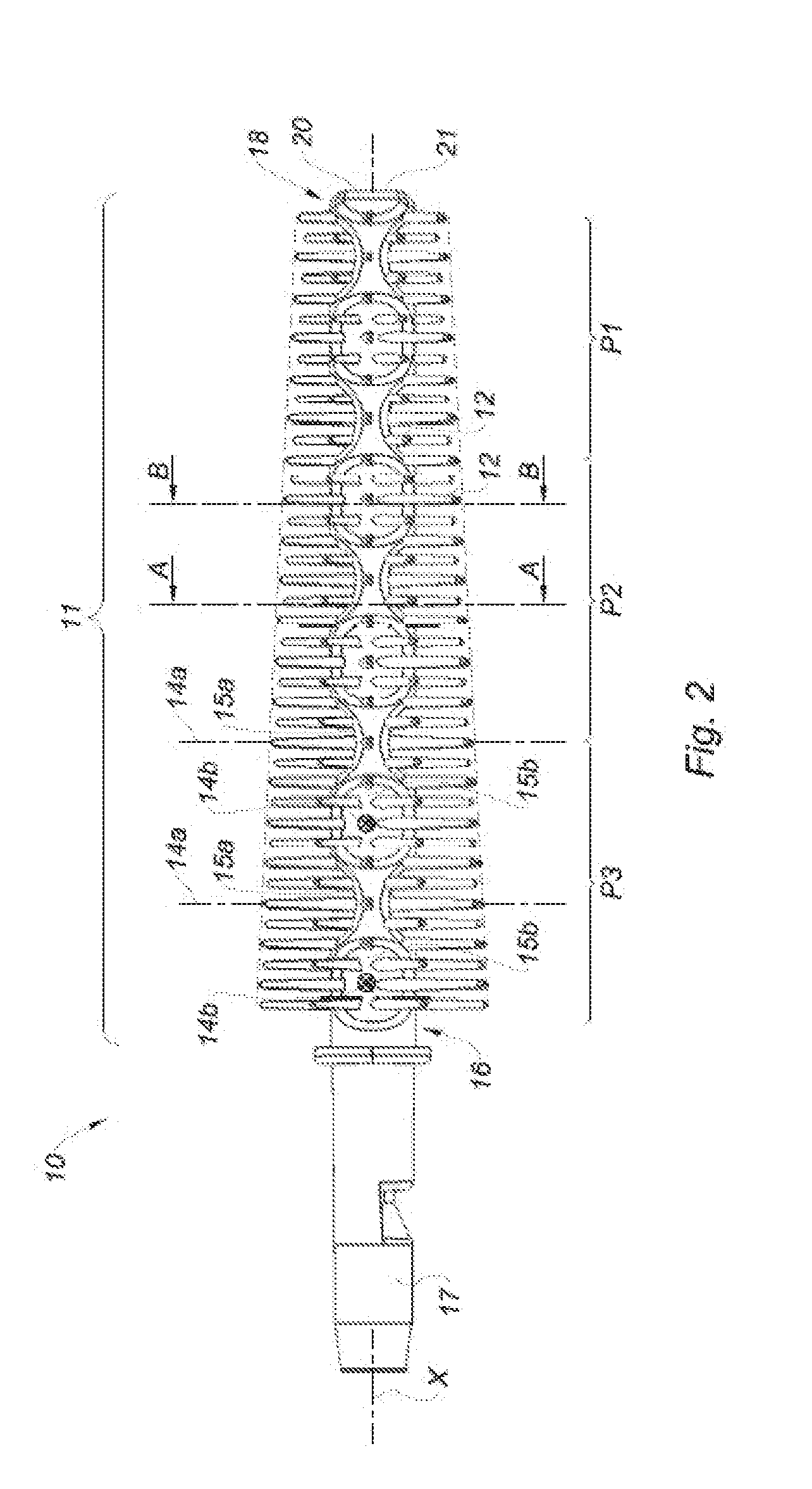
[0047] FIG. 2 is a bottom view of the applicator shown in FIG. 1;
[0048] FIG. 3 is a front view of the applicator shown in FIGS. 1 and 2;
[0049] FIG. 4 is a slightly inclined isometric view of the applicator shown in FIGS. 1 to 3;
[0050] FIGS. 5a and 5b are cross-section views of the applicator, in two different locations: see mark A-A (FIG. 5a) and B-B (FIG. 5b) in FIG. 2;
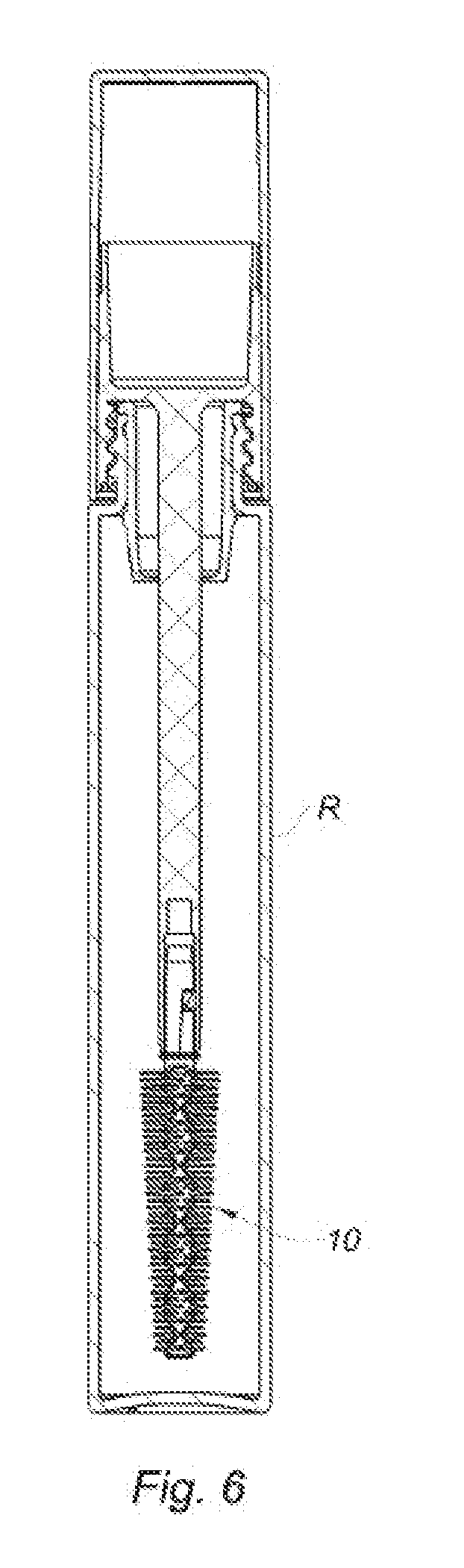
[0051] FIG. 6 is a view of an example of an applicator assembly according to the invention.
[0052] FIGS. 1 to 4 and 5a, 5b show an applicator 10 for cosmetic product according to an embodiment of the invention. The cosmetic product is in particular intended to be applied on the eyelashes such as mascara.
[0053] The applicator 10 comprises a core 11 extending along a main longitudinal extension direction X, referred to as the main direction X, and a plurality of protrusions 12 projecting from the core 11. The term "protrusions projecting from the core" means that the protrusions 12 comprise a base located on the core 11 and which extend in the direction of an opposite free end 24.
[0054] The core 11 further comprises a plurality of flexible zones 13a, 13b arranged in succession along the main direction X, on which the core 11 is thinned along a thinning axis 14a, 14b substantially orthogonal relative to the main direction X, so as to form two cavities 15a, 15b radially opposed relative to said main direction X (see FIGS. 1, 2 and 4).
[0055] In other words, on each flexible zone 13a, 13b, the core 11 is thinned along a thinning axis 14a, 14b. This thinning is carried out, along the thinning axis 14a, 14b, on one side as well as the other of the main direction X, thus forming the two cavities 15a, 15b. Again in other words, on each flexible zone 13a, 13b, the core 11 is thinned in a globally symmetrical manner on either side of the main direction X.
[0056] In this way, the core 11 is more flexible on cavities 15a, 15b of the flexible zones 13a, 13b, with this flexibility being transmitted to the protrusions 12 arranged on said cavities 15a, 15b so as in particular to apply the cosmetic product with more precision on these flexible zones 13a, 13b. Thus, it is possible to locally increase the precision of the applicator 10 without however increasing the length of the protrusions 12 in order to increase the flexibility thereof and therefore without losing any charge of cosmetic product on said protrusions 12. The applicator 10 therefore makes it possible to both comb the eyelashes and to give them volume, during the application of the cosmetic product. Furthermore, the cavities 15a, 15b form reservoirs of cosmetic product, thus making it possible to charge more the protrusions 12 with cosmetic product for the purpose of giving more volume to the eyelashes, during the application of said cosmetic product.
[0057] At least one of the flexible zones 13a, 13b has an angularly offset thinning axis 14a, 14b, about the main direction X, in relation to the thinning axis 14b, 14a of a flexible zone 13b, 13a which is adjacent to it. The term "angularly offset" describes the fact that said thinning axes 14a, 14b together form a non-zero offset angle .alpha. that is strictly less than 180.degree.. The offset angle .alpha. is visible in FIGS. 3 and 4. The term "angularly offset" also describes the fact that said thinning axes 14a, 14b are not parallel with one another.
[0058] In this way, the core 11 has flexible zones 13a, 13b, which can each bend about an axis 22, referred to as the transversal axis, orthogonal to the main direction X and to the thinning axis 14a, 14b associated with said flexible zone 13a, 13b, these transversal axes 22 being able to be different from one flexible zone 13a, 13b to another. Thus, it is not necessary to give to the applicator 10 a specific initial orientation before applying the cosmetic product, the applicator 10 being flexible, along the core 11, about several transversal axes 22. The user of the applicator of the invention therefore does not have to adapt their usual gesture.
[0059] The core 11 is shown here solid. It can however be hollow without departing from the scope of the invention.
[0060] The core 11 comprises, along the main direction X, a proximal end 16 extended by a sleeve 17 without protrusions and a distal end 18 opposite the proximal portion 16. The sleeve 17 is intended to cooperate with a stem (not shown). The distal end 18 comprises a free end 20. The free end 20 has for example a flat surface 21 arranged perpendicularly to the main direction X. The free end 20 is devoid of protrusions 12.
[0061] Alternatively, the free end 20 can have protrusions 12.
[0062] The core 11 can comprise a succession of flexible zones 13a, 13b that have thinning axes 14a, 14b which are angularly offset relative to one another, about the main direction X.
[0063] The core 11 comprises for example an alternation of first flexible zones 13a of which the thinning axes 14a are parallel to one another and of second flexible zones 13b of which the thinning axes 14b are parallel to one another and angularly offset relative to the thinning axes 14a of the first flexible zones 13a, about the main direction X (FIGS. 1, 2, 3, 4, 5a and 5b).
[0064] By way of example, one flexible zone out of two, along the main direction X, is a first flexible zone 13a and one flexible zone out of two, along the main direction X, is a second flexible zone 13b. Other patterns of first and of second flexible zones 13a, 13b can be provided without departing from the scope of the invention. It is possible in particular to have a succession of at least two first flexible zones 13a with one or several second flexible zones 13b.
[0065] The offset angle .alpha. between the thinning axes 14a, 14b of the first and second flexible zones 13a, 13b is for example between 45 and 135.degree.. Preferably, the offset angle .alpha. is about 90.degree. (FIGS. 1, 2, 4, 5a and 5b). In other words, the core 11 preferably comprises an alternation of flexible zones 13a, 13b having thinning axes 14a, 14b orthogonal with respect to one another.
[0066] This is shown in FIGS. 5a and 5b, which each show a section of the core 11 along the main direction X, in two separate locations along this direction X--see FIG. 2 for the positioning of the axis of section A-A (FIG. 5a) and for that of section B-B (FIG. 5b). FIG. 5a shows a section with a substantially rectangular shape of which the largest side extends along the axis 14b; while FIG. 5b shows a substantially rectangular section of which the largest side extends along the axis 14a, with these two axes here being orthogonal.
[0067] The flexible zones 13a, 13b can be located on a discrete portion of the main direction X of the core 11. In other words, the flexible zones 13a, 13b can be located on only one portion of the core 11. The flexible zones 13a, 13b are for example located on a portion of the core 11 (embodiments not shown here).
[0068] For example, they can be located on first portion P1 of the core 11, that extends from the distal end 18 of the core 11 to the proximal end 16 the core 11 over a distance that does not exceed half of the length of the core 11 (see FIG. 2 for the marking of the zones P1, P2 and P3).
[0069] They can also be located on second portion P2 of the core 11, which extends between the distal end 18 of the core 11 and the proximal end 16 the core 11 over a distance that does not exceed half of the length of the core 11.
[0070] They can also be located on third portion P3 of the core 11, that extends from the proximal end 16 of the core 11 to the distal end 18 of the core 11 over a distance that does not exceed half of the length of the core 11.
[0071] They can also result from a combination of the aforementioned examples, without departing from the scope of the invention; namely, they can be located on the first and second portions P1, P2, on the first and third portions P1, P3 and/or on the second and third portions P2, P3.
[0072] The cavities 15a, 15b formed by the thinning of the core 11 are for example symmetrical relative to a plane substantially orthogonal to the thinning axis 14a, 14b that they are associated with and comprising the main direction X.
[0073] The cavities 15a, 15b can furthermore be concave along the main direction X.
[0074] The cavities 15a, 15b can also have a polygonal shape, for example triangular or square or rectangular, along the main direction X. The edges of the cavities 15a, 15b can furthermore be attenuated by fillets or rounded edges.
[0075] The cavities 15a, 15b have for example a maximum dimension along the transversal axis 22 that they are associated with, referred to as transversal dimension D.sub.T, equal to the maximum diameter d.sub.max of the core 11 (FIG. 1). In this way, the cavities 15a, 15b each form a groove extending along the transversal axis 22 that they are associated with, which opens onto each one of its ends along said transversal axis 22. This increases the flexibility of the core 11 on the flexible zones 13a, 13b.
[0076] The cavities 15a, 15b of the flexible zones 13a, 13b can be of an equal maximum dimension along the main direction X, said maximum dimension referred to as longitudinal dimension D.sub.L1. The longitudinal dimension D.sub.L1 of the cavities 15a, 15b of the flexible zones 13a, 13b is for example between 1.5 and 15 mm. The longitudinal dimension D.sub.L1 is preferably about 1.8 mm.
[0077] Alternatively, the longitudinal dimension D.sub.L1 of the cavities 15a, 15b of the flexible zones 13a, 13b can vary from one flexible zone to another.
[0078] Furthermore, the cavities 15a, 15b of the flexible zones 13a, 13b can have the same depth along the thinning axis 14a, 14b that they are associated with. Alternatively, the depth of the cavities 15a, 15b of the flexible zones 13a, 13b can vary from one flexible zone to another.
[0079] The free end 20 of the core 11 has for example, along the main direction X, a form comprising a sloped section, even a globally pointed shape. This makes it possible to limit the accumulation of cosmetic product on said free end 20 and therefore to prevent the nose of the user from becoming dirty when manipulating the applicator 10.
[0080] For this, the free end 20 of the core 11 can itself include a flexible zone 13c on which said free end 20 of the core 11 is thinned along a thinning axis substantially orthogonal to the main direction X, so as to form two cavities 15c radially opposed relative to said main direction X (FIG. 3).
[0081] The flexible zone 13c of the free end 20 has a thinning axis angularly offset relative to the thinning axis 14a of the flexible zone 13a which is adjacent thereto. The flexible zone 13c of the free end 20 preferably has a thinning axis substantially orthogonal to the thinning axis 14a of the adjacent flexible zone 13a.
[0082] The two cavities 15c formed at the free end 20 of the core 11 have for example a longitudinal dimension D.sub.L2 less than that of the cavities 15a, 15b of the other flexible zones 13a, 13b. Said longitudinal dimension D.sub.L2 will be between 0.1 and 3 mm.
[0083] It can also have the form of a rounded end, bevelled, straight and/or chamfered, without departing from the scope of the invention.
[0084] The protrusions 12 extend for example radially relative to the main direction X. In other words, the protrusions 12 project according to a direction substantially normal to said main direction X, referred to as the radial direction.
[0085] The plurality of protrusions 12 is for example distributed in rows 23 extending along the main direction X. The rows 23 of protrusions 12 are particularly visible in FIG. 3. The applicator 10 comprises for example twelve rows 23 of protrusions 12.
[0086] A pitch p between the protrusions 12 of the same row 23 is for example between 0.6 and 1.5 mm. The pitch p between the protrusions 12 of the same row is preferably about 1.25 mm. Each row 23 can furthermore have the same pitch p between its protrusions 12 (FIG. 1).
[0087] The rows 23 of protrusions 12 are for example distributed evenly about the main direction X. In other words, the protrusions 12 of each row 23 are arranged at an equal angular distance from the protrusions 12 of the rows 23 that they are adjacent to.
[0088] The protrusions 12 of each row 23 are for example arranged at an angular distance of
.pi. 6 ##EQU00001##
rad in relation to the protrusions 12 of the rows 23 which are adjacent thereto.
[0089] The protrusions 12 of two adjacent rows 23 are for example offset relative to one another along the main direction X.
[0090] The protrusions 12 of a row 23 can furthermore be offset by the same distance along the main direction X, relative to the protrusions 12 of the two rows 23 that are adjacent thereto.
[0091] The protrusions 12 of one row 23 out of two are for example offset by the same distance along the main direction X, relative to the protrusions 12 of the rows 23 that are adjacent thereto. The protrusions of one row 23 out of two can furthermore be offset, even staggered along the main direction X, in relation to the protrusions 12 of the rows 23 that are adjacent thereto.
[0092] It is interesting to note that the free ends 24 of the protrusions 12 together define a surface E.
[0093] The surface E has for example a globally frusto-conical shape.
[0094] Preferably, the small section of the frusto-conical cone formed by the surface E is arranged facing the free end 20 of the core 11, while the large section of the frusto-conical cone formed by the surface E is arranged opposite the free end 20 of the core 11.
[0095] The surface has for example a maximum diameter between 4 and 10 m, preferably between 5 and 8 mm.
[0096] The length L of the protrusions 12, defined between the main direction X and the free end 24 of the protrusions 12, varies from one row 23 of protrusions 12 to another. The term "length L of the protrusions 12" describes the radial extension of the protrusions between the X axis of the core 11 and the free end of the protrusion (see FIG. 1). The length L is for example between 2.0 and 5.0 mm and more particularly between 2.5 and 4.0 mm.
[0097] The length L of the protrusions 12 of one row 23 out of two is, on average, less than the length L of the protrusions 12 of the rows 23 that are adjacent thereto.
[0098] The length L of the protrusions 12 can also vary within the same row 23 of protrusions 12.
[0099] The length L of the protrusions 12 of the same row 23 increases for example as the free end 20 of the core 11 is moved away.
[0100] The protrusions 12 are for example globally frusto-conical. The term "globally frusto-conical" describes the fact that the section of the protrusions 12 increases or decreases progressively from the base to the free end 24 of said protrusions 12. Preferably, the base of the protrusions 12 is of greater section than the free end 24 of said protrusions 12.
[0101] The protrusions 12 furthermore each have a section in the shape of a half-ellipse--for example a semi-oval--forming a flat surface 25, and are positioned in such a way that the surfaces planes 25 of the protrusions 12 are oriented in the same gyratory direction.
[0102] The core 11 can comprise protrusions 12 that project from the flexible zones 13a, 13b of the core 11.
[0103] No protrusion 12 can alternatively extend from one, several or all of the flexible zones 13a, 13b of the core 11.
[0104] The protrusions 12 are for example made from the material of the core 11.
[0105] The core 11 can be a moulded core, in particular made of plastic material. The core 11 and the protrusions 12 are for example moulded together. The protrusions 12 can alternatively be overmoulded on the core 12. The core 11 and the protrusions 12 can be moulded in a material with an LDPE (or "low-density polyethylene") base. Other materials can be used, namely the "EXACT" material marketed by the company ExxonMobil or the "HYTREL" material marketed by the company Dupont de Nemours, even a mixture of these materials.
[0106] The maximum diameter d.sub.max of the core 11 is for example between 2 and 6 mm.
[0107] It is understood that the flexible zones 13a, 13b have a particular advantage, when the core 11 has a large maximum diameter d.sub.max, in particular a maximum diameter d.sub.max between 4 and 6 mm. Such cores 11 will be referred to in the rest of the description as "large-diameter cores".
[0108] The large-diameter cores 11 are interesting because the protrusions 12 that project therefrom are globally shorter, for the same diameter of surface E, than a core 11 with a smaller maximum diameter d.sub.max, in such a way that with the large-diameter cores 11, it is possible to work on the eyelashes of the user right from the root and therefore to charge them with more cosmetic product, during the application of the cosmetic product. The large-diameter cores 11 also make it possible to give volume to the eyelashes of the user.
[0109] The large-diameter cores 11 are also interesting because they can receive a larger number of rows of protrusions 12 around the main direction X, and thus improve the combing and therefore the separation of the eyelashes of the user, during the application of the cosmetic product.
[0110] The large-diameter cores 11 however tend to be more rigid due to their large maximum diameter d.sub.max, in such a way that the flexible zones 13a, 13b make it possible to compensate this tendency by providing them with more flexibility and thus by increasing the precision with which the cosmetic product is applied on the eyelashes of the user.
[0111] Where applicable, the protrusions 12 projecting from the flexible zones 13a, 13b of the large-diameter cores 11 are furthermore longer and therefore more flexible, without the maximum diameter of the surface E being increased, in such a way that said protrusions 12 make it possible, in complementarity with the flexible zones 13a, 13b, to improve the combing of the eyelashes of the user and therefore the separation and the lengthening of said eyelashes, during the application of the cosmetic product.
[0112] It is to be noted, also, that the applicator 10 advantageously forms a brush.
[0113] It should also be noted that the invention relates to an applicator assembly for cosmetic product, comprising a container comprising a body forming a reservoir R intended to contain the cosmetic product, and an applicator 10 such as described hereinabove configured to be displaced with respect to the container between a closed position of the assembly in which the applicator 10 is fastened onto the container and the applicator 10 is housed inside the reservoir, and an open position of the assembly in which the applicator 10 releases the container and the applicator is arranged outside the reservoir (see FIG. 6).
[0114] It should be noted also that alternative embodiments are of course possible. In particular it can also be considered, in additional embodiments, not shown here, that:
[0115] the core 11 further comprises third flexible zones of which the thinning axes are parallel to one another and angularly offset relative to the thinning axes 14a, 14b of the first and second flexible zones 13a, 13b;
[0116] the core 11 comprises an alternation of first flexible zones 13a, of second flexible zones 13b and of third flexible zones;
[0117] one flexible zone out of three, along the main direction X, is a first flexible zone 13a, one flexible zone out of three, along the main direction X, is a second flexible zone 13b and one flexible zone out of three, along the main direction X, is a third flexible zone.
[0118] the thinning axes 14a, 14b of the first, second and third flexible zones 13a, 13b respectively form between them an offset angle .alpha. of about 60.degree..
* * * * *
uspto.report is an independent third-party trademark research tool that is not affiliated, endorsed, or sponsored by the United States Patent and Trademark Office (USPTO) or any other governmental organization. The information provided by uspto.report is based on publicly available data at the time of writing and is intended for informational purposes only.
While we strive to provide accurate and up-to-date information, we do not guarantee the accuracy, completeness, reliability, or suitability of the information displayed on this site. The use of this site is at your own risk. Any reliance you place on such information is therefore strictly at your own risk.
All official trademark data, including owner information, should be verified by visiting the official USPTO website at www.uspto.gov. This site is not intended to replace professional legal advice and should not be used as a substitute for consulting with a legal professional who is knowledgeable about trademark law.