Picture Prediction Method And Related Device
CHEN; Huanbang ; et al.
U.S. patent application number 16/460029 was filed with the patent office on 2019-10-24 for picture prediction method and related device. The applicant listed for this patent is HUAWEI TECHNOLOGIES CO., LTD.. Invention is credited to Huanbang CHEN, Fan LIANG, Haitao YANG.
| Application Number | 20190327483 16/460029 |
| Document ID | / |
| Family ID | 62771722 |
| Filed Date | 2019-10-24 |

View All Diagrams
| United States Patent Application | 20190327483 |
| Kind Code | A1 |
| CHEN; Huanbang ; et al. | October 24, 2019 |
PICTURE PREDICTION METHOD AND RELATED DEVICE
Abstract
A picture prediction method includes: determining a reference block of a current block; obtaining location information and motion information of at least two feature points in the reference block; calculating motion information of each subblock in the current block based on the location information and the motion information of the at least two feature points in the reference block; and performing motion compensation prediction on each subblock in the current block based on the motion information of each subblock in the current block, to obtain a prediction block of the current block.
| Inventors: | CHEN; Huanbang; (Shenzhen, CN) ; YANG; Haitao; (Shenzhen, CN) ; LIANG; Fan; (Guangzhou, CN) | ||||||||||
| Applicant: |
|
||||||||||
|---|---|---|---|---|---|---|---|---|---|---|---|
| Family ID: | 62771722 | ||||||||||
| Appl. No.: | 16/460029 | ||||||||||
| Filed: | July 2, 2019 |
Related U.S. Patent Documents
| Application Number | Filing Date | Patent Number | ||
|---|---|---|---|---|
| PCT/CN2018/071351 | Jan 4, 2018 | |||
| 16460029 | ||||
| Current U.S. Class: | 1/1 |
| Current CPC Class: | H04N 19/54 20141101; H04N 19/176 20141101; H04N 19/50 20141101; H04N 19/513 20141101 |
| International Class: | H04N 19/513 20060101 H04N019/513; H04N 19/176 20060101 H04N019/176; H04N 19/54 20060101 H04N019/54 |
Foreign Application Data
| Date | Code | Application Number |
|---|---|---|
| Jan 4, 2017 | CN | 201710005575.6 |
Claims
1. A method of picture prediction, comprising: determining a reference block of a current block, wherein the reference block and the current block are spatially adjacent, and the reference block is predicted by using an affine motion model; obtaining location information and motion information of at least two feature points in the reference block, wherein the at least two feature points are located in subblocks in which at least two control points in the reference block are located, the at least two control points are used in the affine motion model used for reconstructing the reference block, and motion information of the subblock in which a feature point is located is obtained based on the motion information of a corresponding feature point; and calculating motion information of each subblock in the current block based on the location information and the motion information of the at least two feature points in the reference block; and performing motion compensation prediction on each subblock in the current block based on the motion information of each subblock in the current block, to obtain a prediction block of the current block.
2. The method according to claim 1, wherein the feature point is in a central location of the subblock in which the control point in the reference block is located.
3. The method according to claim 1, wherein the location information of the feature point in the reference block is obtained by offsetting location information of the control point in the reference block in the following manner: (x',y')=(x+a,y+b), (x,y) are coordinates of a control point in the reference block, (x',y') are coordinates of a feature point in a subblock in which the control point whose coordinates are (x,y) in the reference block is located, a is a horizontal offset, b is a vertical offset, and a and b are not equal to 0.
4. The method according to claim 1, wherein the at least two control points in the reference block comprise at least two of an upper left vertex, an upper right vertex, a lower left vertex, and a lower right vertex of the reference block, and when location coordinates of the upper left vertex of the reference block are (x.sub.0,y.sub.0), a width of the reference block is w, and a height of the reference block is h, { ( x 1 , y 1 ) = ( x 0 + w , y 0 ) ( x 2 , y 2 ) = ( x 0 , y 0 + h ) ( x 3 , y 3 ) = ( x 0 + w , y 0 + h ) ##EQU00023## wherein (x.sub.1,y.sub.1) are coordinates of the upper right vertex of the reference block, (x.sub.2,y.sub.2) are coordinates of the lower left vertex of the reference block, and (x.sub.3,y.sub.3) are coordinates of the lower right vertex of the reference block.
5. The method according to claim 1, wherein the at least two feature points comprise feature points whose coordinates are respectively (x.sub.0',y.sub.0') and (x.sub.1',y.sub.1') in the reference block, wherein { ( x 0 ' , y 0 ' ) = ( x 0 + N 1 / 2 , y 0 + N 2 / 2 ) ( x 1 ' , y 1 ' ) = ( x 1 - N 1 / 2 , y 0 + N 2 / 2 ) , or { ( x 0 ' , y 0 ' ) = ( x 0 + N 1 / 2 , y 0 + N 2 / 2 ) ( x 1 ' , y 1 ' ) = ( x 0 + w - N 1 / 2 , y 0 + N 2 / 2 ) , ##EQU00024## wherein N.sub.1 is a width of the subblock in which the control point in the reference block is located, N.sub.2 is a height of the subblock in which the control point in the reference block is located, (x.sub.0,y.sub.0) are coordinates of a control point in a subblock in which the feature point (x.sub.0',y.sub.0') in the reference block is located, (x.sub.1,y.sub.1) are coordinates of a control point in a subblock in which the feature point (x.sub.1',y.sub.1') in the reference block is located, and W is the width of the reference block.
6. The method according to claim 1, wherein the at least two feature points comprise feature points whose coordinates are respectively (x.sub.0',y.sub.0'), (x.sub.1',y.sub.1') and (x.sub.2',y.sub.2') in the reference block, wherein { ( x 0 ' , y 0 ' ) = ( x 0 + N 1 / 2 , y 0 + N 2 / 2 ) ( x 1 ' , y 1 ' ) = ( x 1 - N 1 / 2 , y 1 + N 2 / 2 ) ( x 2 ' , y 2 ' ) = ( x 2 + N 1 / 2 , y 2 - N 2 / 2 ) , or { ( x 0 ' , y 0 ' ) = ( x 0 + N 1 / 2 , y 0 + N 2 / 2 ) ( x 1 ' , y 1 ' ) = ( x 0 + w - N 1 / 2 , y 0 + N 2 / 2 ) ( x 2 ' , y 2 ' ) = ( x 0 + N 1 / 2 , y 0 + h - N 2 / 2 ) , ##EQU00025## wherein N.sub.1 is a width of the subblock in which the control point in the reference block is located, N.sub.2 is a height of the subblock in which the control point in the reference block is located, (x.sub.0,y.sub.0) are coordinates of a control point in a subblock in which the feature point (x.sub.0',y.sub.0') in the reference block is located, (x.sub.1,y.sub.1) are coordinates of a control point in a subblock in which the feature point (x.sub.1',y.sub.1') in the reference block is located, (x.sub.2,y.sub.2) are coordinates of a control point in a subblock in which the feature point (x.sub.2',y.sub.2') in the reference block is located, w is the width of the reference block, and h is the height of the reference block.
7. The method according to claim 1, wherein the at least two feature points comprise feature points whose coordinates are respectively (x.sub.0',y.sub.0'), (x.sub.1',y.sub.1'), (x.sub.2',y.sub.2'), and (x.sub.3',y.sub.3') in the reference block, wherein { ( x 0 ' , y 0 ' ) = ( x 0 + N 1 / 2 , y 0 + N 2 / 2 ) ( x 1 ' , y 1 ' ) = ( x 1 - N 1 / 2 , y 1 + N 2 / 2 ) ( x 2 ' , y 2 ' ) = ( x 2 + N 1 / 2 , y 2 - N 2 / 2 ) ( x 3 ' , y 3 ' ) = ( x 3 - N 1 / 2 , y 3 - N 2 / 2 ) , or { ( x 0 ' , y 0 ' ) = ( x 0 + N 1 / 2 , y 0 + N 2 / 2 ) ( x 1 ' , y 1 ' ) = ( x 0 + w - N 1 / 2 , y 0 + N 2 / 2 ) ( x 2 ' , y 2 ' ) = ( x 0 + N 1 / 2 , y 0 + h - N 2 / 2 ) ( x 3 ' , y 3 ' ) = ( x 0 + w - N 1 / 2 , y 0 + h - N 2 / 2 ) , ##EQU00026## wherein N.sub.1 is a width of the subblock in which the control point in the reference block is located, N.sub.2 is a height of the subblock in which the control point in the reference block is located, (x.sub.0,y.sub.0) are coordinates of a control point in a subblock in which the feature point (x.sub.0',y.sub.0') in the reference block is located, (x.sub.1,y.sub.1) are coordinates of a control point in a subblock in which the feature point (x.sub.1',y.sub.1') in the reference block is located, (x.sub.2,y.sub.2) are coordinates of a control point in a subblock in which the feature point (x.sub.2',y.sub.2') in the reference block is located, (x.sub.3,y.sub.3) are coordinates of a control point in a subblock in which the feature point (x.sub.3',y.sub.3') in the reference block is located, w is the width of the reference block, and h is the height of the reference block.
8. The method according to claim 5, wherein calculating the motion information of each subblock in the current block based on the location information and the motion information of the at least two feature points in the reference block comprises: calculating the motion information of each subblock in the current block based on the location information and the motion information of the at least two feature points in the reference block and location information of each subblock in the current block.
9. The method according to claim 8, wherein calculating the motion information of each subblock in the current block based on the location information and the motion information of the at least two feature points in the reference block and location information of each subblock in the current block comprises: calculating the motion information of each subblock in the current block with reference to the following formula and based on the location information and the motion information of the at least two feature points in the reference block and the location information of each subblock in the current block: { vx = vx 1 - vx 0 x 1 ' - x 0 ' .times. ( x - x 0 ' ) - vy 1 - vy 0 x 1 ' - x 0 ' .times. ( y - y 0 ' ) + vx 0 vy = vy 1 - vy 0 x 1 ' - x 0 ' .times. ( x - x 0 ' ) + vx 1 - vx 0 x 1 ' - x 0 ' .times. ( y - y 0 ' ) + vy 0 , or { vx = vx 1 - vx 0 x 1 ' - x 0 ' .times. ( x - x 0 ' ) + vx 2 - vx 0 x 2 ' - x 0 ' .times. ( y - y 0 ' ) + vx 0 vy = vy 1 - vy 0 x 1 ' - x 0 ' .times. ( x - x 0 ' ) + vy 2 - vy 0 y 2 ' - y 0 ' .times. ( y - y 0 ' ) + vy 0 , or { vx = vx 1 - vx 0 x 1 ' - x 0 ' .times. ( x - x 0 ' ) + vx 2 - vx 0 y 2 ' - y 0 ' .times. ( y - y 0 ' ) + ( vx 3 + vx 0 ) - ( vx 1 + vx 2 ) ( x 1 ' - x 0 ' ) .times. ( y 2 ' - y 0 ' ) .times. ( x - x 0 ' ) .times. ( y - y 0 ' ) + vx 0 vy = vy 1 - vy 0 x 1 ' - x 0 ' .times. ( x - x 0 ' ) + vy 2 - vy 0 y 2 ' - y 0 ' .times. ( y - y 0 ' ) + ( vy 3 + vy 0 ) - ( vy 1 + vy 2 ) ( x 1 ' - x 0 ' ) .times. ( y 2 ' - y 0 ' ) .times. ( x - x 0 ' ) .times. ( y - y 0 ' ) + vy 0 , ##EQU00027## wherein the at least two feature points comprise the feature points whose coordinates are (x.sub.0',y.sub.0') and (x.sup.1',y.sub.1') in the reference block; the at least two feature points comprise at least two of the feature points whose coordinates are (x.sub.0',y.sub.0'), (x.sub.1',y.sub.1'), and (x.sub.2',y.sub.2') in the reference block; or the at least two feature points comprise at least two of the feature points whose coordinates are (x.sub.0',y.sub.0'), (x.sub.1',y.sub.1'), (x.sub.2',y.sub.2'), and (x.sub.3',y.sub.3') in the reference block, wherein vx.sub.0 is a horizontal motion vector of the feature point (x.sub.0',y.sub.0'), vy.sub.0 is a vertical motion vector of the feature point (x.sub.0',y.sub.0'), vx.sub.1 is a horizontal motion vector of the feature point (x.sub.1',y.sub.1'), vy.sub.1 is a vertical motion vector of the feature point (x.sub.1',y.sub.1'), vy.sup.2 is a vertical motion vector of the feature point (x.sub.2',y.sub.2'), vx.sub.2 is a horizontal motion vector of the feature point (x.sub.2',y.sub.2'), vy.sub.3 is a vertical motion vector of the feature point (x.sub.3',y.sub.3'), and vx.sub.3 is a horizontal motion vector of the feature point (x.sub.3',y.sub.3'); and vx is a horizontal motion vector of a subblock whose coordinates are (x,y) in the current block, and Vy is a vertical motion vector of the subblock whose coordinates are (x,y) in the current block.
10. The method according to claim 5, wherein calculating the motion information of each subblock in the current block based on the location information and the motion information of the at least two feature points in the reference block comprises: calculating, based on the location information and the motion information of the at least two feature points in the reference block, motion information of at least two control points used in an affine motion model used for the current block; and calculating the motion information of each subblock in the current block based on location information of each subblock in the current block and the motion information and location information of the at least two control points used in the affine motion model used for the current block.
11. The method according to claim 10, wherein calculating, based on the location information and the motion information of the at least two feature points in the reference block, the motion information of at least two control points used in an affine motion model used for the current block comprises: calculating, with reference to the following formula and based on the location information and the motion information of the at least two feature points in the reference block, the motion information of the at least two control points used in the affine motion model used for the current block: { vx 4 = vx 1 - vx 0 x 1 ' - x 0 ' .times. ( x 4 - x 0 ' ) - vy 1 - vy 0 x 1 ' - x 0 ' .times. ( y 4 - y 0 ' ) + vx 0 vy 4 = vy 1 - vy 0 x 1 ' - x 0 ' .times. ( x 4 - x 0 ' ) + vx 1 - vx 0 x 1 ' - x 0 ' .times. ( y 4 - y 0 ' ) + vy 0 { vx 5 = vx 1 - vx 0 x 1 ' - x 0 ' .times. ( x 5 - x 0 ' ) - vy 1 - vy 0 x 1 ' - x 0 ' .times. ( y 5 - y 0 ' ) + vx 0 vy 5 = vy 1 - vy 0 x 1 ' - x 0 ' .times. ( x 5 - x 0 ' ) + vx 1 - vx 0 x 1 ' - x 0 ' .times. ( y 5 - y 0 ' ) + vy 0 , or { vx 4 = vx 1 - vx 0 x 1 ' - x 0 ' .times. ( x 4 - x 0 ' ) + vx 2 - vx 0 x 2 ' - x 0 ' .times. ( y 4 - y 0 ' ) + vx 0 vy 4 = vy 1 - vy 0 x 1 ' - x 0 ' .times. ( x 4 - x 0 ' ) + vy 2 - vy 0 y 2 ' - y 0 ' .times. ( y 4 - y 0 ' ) + vy 0 { vx 5 = vx 1 - vx 0 x 1 ' - x 0 ' .times. ( x 5 - x 0 ' ) + vx 2 - vx 0 x 2 ' - x 0 ' .times. ( y 5 - y 0 ' ) + vx 0 vy 5 = vy 1 - vy 0 x 1 ' - x 0 ' .times. ( x 5 - x 0 ' ) + vy 2 - vy 0 y 2 ' - y 0 ' .times. ( y 5 - y 0 ' ) + vy 0 { vx 6 = vx 1 - vx 0 x 1 ' - x 0 ' .times. ( x 6 - x 0 ' ) + vx 2 - vx 0 x 2 ' - x 0 ' .times. ( y 6 - y 0 ' ) + vx 0 vy 6 = vy 1 - vy 0 x 1 ' - x 0 ' .times. ( x 6 - x 0 ' ) + vy 2 - vy 0 y 2 ' - y 0 ' .times. ( y 6 - y 0 ' ) + vy 0 , or { vx 4 = vx 1 - vx 0 x 1 ' - x 0 ' .times. ( x 4 - x 0 ' ) + vx 2 - vx 0 x 2 ' - x 0 ' .times. ( y 4 - y 0 ' ) + ( vx 3 + vx 0 ) - ( vx 1 + vx 2 ) ( x 1 ' - x 0 ' ) .times. ( y 2 ' - y 0 ' ) .times. ( x 4 - x 0 ' ) .times. ( y 4 - y 0 ' ) + vx 0 vy 4 = vy 1 - vy 0 x 1 ' - x 0 ' .times. ( x 4 - x 0 ' ) + vy 2 - vy 0 y 2 ' - y 0 ' .times. ( y 4 - y 0 ' ) + ( vy 3 + vy 0 ) - ( vy 1 + vy 2 ) ( x 1 ' - x 0 ' ) .times. ( y 2 ' - y 0 ' ) .times. ( x 4 - x 0 ' ) .times. ( y 4 - y 0 ' ) + vy 0 { vx 5 = vx 1 - vx 0 x 1 ' - x 0 ' .times. ( x 5 - x 0 ' ) + vx 2 - vx 0 x 2 ' - x 0 ' .times. ( y 5 - y 0 ' ) + ( vx 3 + vx 0 ) - ( vx 1 + vx 2 ) ( x 1 ' - x 0 ' ) .times. ( y 2 ' - y 0 ' ) .times. ( x 5 - x 0 ' ) .times. ( y 5 - y 0 ' ) + vx 0 vy 5 = vy 1 - vy 0 x 1 ' - x 0 ' .times. ( x 5 - x 0 ' ) + vy 2 - vy 0 y 2 ' - y 0 ' .times. ( y 5 - y 0 ' ) + ( vy 3 + vy 0 ) - ( vy 1 + vy 2 ) ( x 1 ' - x 0 ' ) .times. ( y 2 ' - y 0 ' ) .times. ( x 5 - x 0 ' ) .times. ( y 5 - y 0 ' ) + vy 0 { vx 6 = vx 1 - vx 0 x 1 ' - x 0 ' .times. ( x 6 - x 0 ' ) + vx 2 - vx 0 x 2 ' - x 0 ' .times. ( y 6 - y 0 ' ) + ( vx 3 + vx 0 ) - ( vx 1 + vx 2 ) ( x 1 ' - x 0 ' ) .times. ( y 2 ' - y 0 ' ) .times. ( x 6 - x 0 ' ) .times. ( y 6 - y 0 ' ) + vx 0 vy 6 = vy 1 - vy 0 x 1 ' - x 0 ' .times. ( x 6 - x 0 ' ) + vy 2 - vy 0 y 2 ' - y 0 ' .times. ( y 6 - y 0 ' ) + ( vy 3 + vy 0 ) - ( vy 1 + vy 2 ) ( x 1 ' - x 0 ' ) .times. ( y 2 ' - y 0 ' ) .times. ( x 6 - x 0 ' ) .times. ( y 6 - y 0 ' ) + vy 0 { vx 7 = vx 1 - vx 0 x 1 ' - x 0 ' .times. ( x 7 - x 0 ' ) + vx 2 - vx 0 x 2 ' - x 0 ' .times. ( y 7 - y 0 ' ) + ( vx 3 + vx 0 ) - ( vx 1 + vx 2 ) ( x 1 ' - x 0 ' ) .times. ( y 2 ' - y 0 ' ) .times. ( x 7 - x 0 ' ) .times. ( y 7 - y 0 ' ) + vx 0 vy 7 = vy 1 - vy 0 x 1 ' - x 0 ' .times. ( x 7 - x 0 ' ) + vy 2 - vy 0 y 2 ' - y 0 ' .times. ( y 7 - y 0 ' ) + ( vy 3 + vy 0 ) - ( vy 1 + vy 2 ) ( x 1 ' - x 0 ' ) .times. ( y 2 ' - y 0 ' ) .times. ( x 7 - x 0 ' ) .times. ( y 7 - y 0 ' ) + vy 0 , ##EQU00028## wherein the at least two feature points comprise the feature points whose coordinates are (x.sub.0',y.sub.0') and (x.sub.1',y.sub.1') in the reference block; the at least two feature points comprise at least two of the feature points whose coordinates are (x.sub.0',y.sub.0'), (x.sub.1',y.sub.1'), (x.sub.2',y.sub.2'), and (x.sub.3',y.sub.3') in the reference block, wherein the at least two feature points comprise at least two of the feature points whose coordinates are (x.sub.0',y.sub.0'), (x.sub.1',y.sub.1'), and (x.sub.2',y.sub.2') in the reference block; or the at least two control points used in the affine motion model used for the current block comprise control points whose coordinates are respectively (x.sub.4,y.sub.4) and (x.sub.5,y.sub.5) in the current block; the at least two control points used in the affine motion model used for the current block comprise at least two of control points whose coordinates are respectively (x.sub.4,y.sub.4), (x.sub.5,y.sub.5), and (x.sub.6,y.sub.6) in the current block; or the at least two control points used in the affine motion model used for the current block comprise at least two of control points whose coordinates are respectively (x.sub.4,y.sub.4), (x.sub.5,y.sub.5), (x.sub.6,y.sub.6), and (x.sub.7,y.sub.7) in the current block; and vx.sub.4 is a horizontal motion vector of the control point (x.sub.4,y.sub.4), vy.sub.4 is a vertical motion vector of the control point (x.sub.4,y.sub.4); vx.sub.5 is a horizontal motion vector of the control point (x.sub.5,y.sub.5) vy.sub.5 is a vertical motion vector of the control point (x.sub.5,y.sub.5), vx.sub.6 is a horizontal motion vector of the control point (x.sub.6,y.sub.6), vy.sub.6 is a vertical motion vector of the control point (x.sub.6,y.sub.6), vx.sub.7 is a horizontal motion vector of the control point (x.sub.7,y.sub.7), and vy.sub.7 is a vertical motion vector of the control point (x.sub.7,y.sub.7).
12. The method according to claim 11, wherein calculating the motion information of each subblock in the current block based on location information of each subblock in the current block and the motion information and location information of the at least two control points used in the affine motion model used for the current block comprises: calculating the motion information of each subblock in the current block with reference to the following formula and based on the location information of each subblock in the current block and the motion information and the location information of the at least two control points used in the affine motion model used for the current block: { vx = vx 5 - vx 4 x 5 - x 4 .times. ( x - x 4 ) - vy 5 - vy 4 x 5 - x 4 .times. ( y - y 4 ) + vx 4 vy = vy 5 - vy 4 x 5 - x 4 .times. ( x - x 4 ) + vx 1 - vx 0 x 5 - x 4 .times. ( y - y 4 ) + vy 4 or { vx = vx 5 - vx 4 x 5 - x 4 .times. ( x - x 4 ) + vx 6 - vx 4 x 6 - x 4 .times. ( y - y 4 ) + vx 4 vy = vy 5 - vy 4 x 5 - x 4 .times. ( x - x 4 ) + vy 6 - vy 4 x 6 - x 4 .times. ( y - y 4 ) + vy 4 or { vx = vx 5 - vx 4 x 5 - x 4 .times. ( x - x 4 ) + vx 6 - vx 4 y 6 - y 4 .times. ( y - y 4 ) + ( vx 7 + vx 4 ) - ( vx 5 + vx 6 ) ( x 5 - x 4 ) .times. ( y 6 - y 4 ) .times. ( x - x 4 ) .times. ( y - y 4 ) + vx 4 vy = vy 5 - vy 4 x 5 - x 4 .times. ( x - x 4 ) + vy 6 - vy 4 y 6 - y 4 .times. ( y - y 4 ) + ( vy 7 + vy 4 ) - ( vy 5 + vy 6 ) ( x 5 - x 4 ) .times. ( y 6 - y 4 ) .times. ( x - x 4 ) .times. ( y - y 4 ) + vy 4 , ##EQU00029## wherein vx is a horizontal motion vector of a subblock whose coordinates are (x,y) in the current block, and vy is a vertical motion vector of the subblock whose coordinates are (x,y) in the current block.
13. The method according to claim 1, wherein the method is applied to a video coding process or a video decoding process.
14. An apparatus for picture prediction, comprising: a determining unit configured to determine a reference block of a current block, wherein the reference block and the current block are spatially adjacent, and the reference block is predicted by using an affine motion model; an obtaining unit configured to obtain location information and motion information of at least two feature points in the reference block, wherein the at least two feature points are located in subblocks in which at least two control points in the reference block are located, the at least two control points are control points used in the affine motion model used for the reference block, and motion information of the subblock in which a feature point is located is obtained based on the motion information of a corresponding feature point; and a calculation unit configured to calculate motion information of each subblock in the current block based on the location information and the motion information of the at least two feature points in the reference block; and a prediction unit configured to perform motion compensation prediction on each subblock in the current block based on the motion information of each subblock in the current block, to obtain a prediction block of the current block.
15. The apparatus according to claim 14, wherein the feature point is in a central location of the subblock in which the control point in the reference block is located.
16. The apparatus according to claim 14, wherein the location information of the feature point in the reference block is obtained by offsetting location information of the control point in the reference block in the following manner: (x',y')=(x+a,y+b), (x,y) are coordinates of a control point in the reference block, (x',y') are coordinates of a feature point in a subblock in which the control point whose coordinates are (x,y) in the reference block is located, a is a horizontal offset, b is a vertical offset, and a and b are not equal to 0.
17. The apparatus according to claim 14, wherein the at least two control points in the reference block comprise at least two of an upper left vertex, an upper right vertex, a lower left vertex, and a lower right vertex of the reference block, and when location coordinates of the upper left vertex of the reference block are (x.sub.0,y.sub.0), a width of the reference block is w, and a height of the reference block is h, { ( x 1 , y 1 ) = ( x 0 + w , y 0 ) ( x 2 , y 2 ) = ( x 0 , y 0 + h ) ( x 3 , y 3 ) = ( x 0 + w , y 0 + h ) , ##EQU00030## wherein (x.sub.1,y.sub.1) are coordinates of the upper right vertex of the reference block, (x.sub.2,y.sub.2) are coordinates of the lower left vertex of the reference block, and (x.sub.3,y.sub.3) are coordinates of the lower right vertex of the reference block.
18. The apparatus according to claim 14, wherein the at least two feature points comprise feature points whose coordinates are respectively (x.sub.0',y.sub.0') and (x.sub.1',y.sub.1') in the reference block, wherein { ( x 0 ' , y 0 ' ) = ( x 0 + N 1 / 2 , y 0 + N 2 / 2 ) ( x 1 ' , y 1 ' ) = ( x 1 - N 1 / 2 , y 1 + N 2 / 2 ) , or { ( x 0 ' , y 0 ' ) = ( x 0 + N 1 / 2 , y 0 + N 2 / 2 ) ( x 1 ' , y 1 ' ) = ( x 0 + w - N 1 / 2 , y 0 + N 2 / 2 ) , ##EQU00031## wherein N.sub.1 is a width of the subblock in which the control point in the reference block is located, N.sub.2 is a height of the subblock in which the control point in the reference block is located, (x.sub.0,y.sub.0) are coordinates of a control point in a subblock in which the feature point (x.sub.0',y.sub.0') in the reference block is located, (x.sub.1,y.sub.1) are coordinates of a control point in a subblock in which the feature point (x.sub.1',y.sub.1') in the reference block is located, and w is the width of the reference block.
19. The apparatus according to claim 14, wherein the at least two feature points comprise feature points whose coordinates are respectively (x.sub.0',y.sub.0'), (x.sub.1',y.sub.1'), and (x.sub.2',y.sub.2') in the reference block, wherein { ( x 0 ' , y 0 ' ) = ( x 0 + N 1 / 2 , y 0 + N 2 / 2 ) ( x 1 ' , y 1 ' ) = ( x 1 - N 1 / 2 , y 1 + N 2 / 2 ) ( x 2 ' , y 2 ' ) = ( x 2 + N 1 / 2 , y 2 - N 2 / 2 ) , or { ( x 0 ' , y 0 ' ) = ( x 0 + N 1 / 2 , y 0 + N 2 / 2 ) ( x 1 ' , y 1 ' ) = ( x 0 + w - N 1 / 2 , y 0 + N 2 / 2 ) ( x 2 ' , y 2 ' ) = ( x 0 + N 1 / 2 , y 0 + h - N 2 / 2 ) , ##EQU00032## wherein N.sub.1 is a width of the subblock in which the control point in the reference block is located, N.sub.2 is a height of the subblock in which the control point in the reference block is located, (x.sub.0,y.sub.0) are coordinates of a control point in a subblock in which the feature point (x.sub.0',y.sub.0') in the reference block is located, (x.sub.1,y.sub.1) are coordinates of a control point in a subblock in which the feature point (x.sub.1',y.sub.1') in the reference block is located, (x.sub.2,y.sub.2) are coordinates of a control point in a subblock in which the feature point (x.sub.2',y.sub.2') in the reference block is located, w is the width of the reference block, and h is the height of the reference block.
20. The apparatus according to claim 14, wherein the at least two feature points comprise feature points whose coordinates are respectively (x.sub.0',y.sub.0'), (x.sub.1',y.sub.1'), (x.sub.2',y.sub.2'), and (x.sub.3',y.sub.3') in the reference block, wherein { ( x 0 ' , y 0 ' ) = ( x 0 + N 1 / 2 , y 0 + N 2 / 2 ) ( x 1 ' , y 1 ' ) = ( x 1 - N 1 / 2 , y 1 + N 2 / 2 ) ( x 2 ' , y 2 ' ) = ( x 2 + N 1 / 2 , y 2 - N 2 / 2 ) ( x 3 ' , y 3 ' ) = ( x 3 - N 1 / 2 , y 3 - N 2 / 2 ) , or { ( x 0 ' , y 0 ' ) = ( x 0 + N 1 / 2 , y 0 + N 2 / 2 ) ( x 1 ' , y 1 ' ) = ( x 0 + w - N 1 / 2 , y 0 + N 2 / 2 ) ( x 2 ' , y 2 ' ) = ( x 0 + N 1 / 2 , y 0 + h - N 2 / 2 ) ( x 3 ' , y 3 ' ) = ( x 0 + w - N 1 / 2 , y 0 + h - N 2 / 2 ) , ##EQU00033## wherein N.sub.1 is a width of the subblock in which the control point in the reference block is located, N.sub.2 is a height of the subblock in which the control point in the reference block is located, (x.sub.0',y.sub.0) are coordinates of a control point in a subblock in which the feature point (x.sub.0',y.sub.0') in the reference block is located, (x.sub.1,y.sub.1) are coordinates of a control point in a subblock in which the feature point (x.sub.1',y.sub.1') in the reference block is located, (x.sub.2',y.sub.2') are coordinates of a control point in a subblock in which the feature point (x.sub.2',y.sub.2') in the reference block is located, (x.sub.3,y.sub.3) are coordinates of a control point in a subblock in which the feature point (x.sub.3',y.sub.3') in the reference block is located, w is the width of the reference block, and h is the height of the reference block.
21. The apparatus according to claim 18, wherein to calculate the motion information of each subblock in the current block based on the location information and the motion information of the at least two feature points in the reference block, the calculation unit is configured to calculate the motion information of each subblock in the current block based on the location information and the motion information of the at least two feature points in the reference block and location information of each subblock in the current block.
22. The apparatus according to claim 21, wherein to calculate the motion information of each subblock in the current block based on the location information and the motion information of the at least two feature points in the reference block and location information of each subblock in the current block, the calculation unit is configured to calculate the motion information of each subblock in the current block with reference to the following formula and based on the location information and the motion information of the at least two feature points in the reference block and the location information of each subblock in the current block: { vx = vx 1 - vx 0 x 1 ' - x 0 ' .times. ( x - x 0 ' ) - vy 1 - vy 0 x 1 ' - x 0 ' .times. ( y - y 0 ' ) + vx 0 vy = vy 1 - vy 0 x 1 ' - x 0 ' .times. ( x - x 0 ' ) + vx 1 - vx 0 x 1 ' - x 0 ' .times. ( y - y 0 ' ) + vy 0 , or { vx = vx 1 - vx 0 x 1 ' - x 0 ' .times. ( x - x 0 ' ) + vx 2 - vx 0 x 2 ' - x 0 ' .times. ( y - y 0 ' ) + vx 0 vy = vy 1 - vy 0 x 1 ' - x 0 ' .times. ( x - x 0 ' ) + vy 2 - vy 0 y 2 ' - y 0 ' .times. ( y - y 0 ' ) + vy 0 , or { vx = vx 1 - vx 0 x 1 ' - x 0 ' .times. ( x - x 0 ' ) + vx 2 - vx 0 y 2 ' - y 0 ' .times. ( y - y 0 ' ) + ( vx 3 + vx 0 ) - ( vx 1 + vx 2 ) ( x 1 ' - x 0 ' ) .times. ( y 2 ' - y 0 ' ) .times. ( x - x 0 ' ) .times. ( y - y 0 ' ) + vx 0 vy = vy 1 - vy 0 x 1 ' - x 0 ' .times. ( x - x 0 ' ) + vy 2 - vy 0 y 2 ' - y 0 ' .times. ( y - y 0 ' ) + ( vy 3 + vy 0 ) - ( vy 1 + vy 2 ) ( x 1 ' - x 0 ' ) .times. ( y 2 ' - y 0 ' ) .times. ( x - x 0 ' ) .times. ( y - y 0 ' ) + vy 0 , ##EQU00034## wherein the at least two feature points comprise the feature points whose coordinates are (x.sub.0',y.sub.0') and (x.sub.1',y.sub.1') in the reference block; the at least two feature points comprise at least two of the feature points whose coordinates are (x.sub.0',y.sub.0'), (x.sub.1',y.sub.1'), and (x.sub.2',y.sub.2') in the reference block; or the at least two feature points comprise at least two of the feature points whose coordinates are (x.sub.0',y.sub.0'), (x.sub.1',y.sub.1'), (x.sub.2',y.sub.2'), and (x.sub.3',y.sub.3') in the reference block, wherein vx.sub.0 is a horizontal motion vector of the feature point (x.sub.0',y.sub.0'), vy.sub.0 is a vertical motion vector of the feature point (x.sub.0',y.sub.0'), vx.sub.1 is a horizontal motion vector of the feature point (x.sub.1',y.sub.1'), vy.sub.1 is a vertical motion vector of the feature point (x.sub.1',y.sub.1'), vy.sub.2 is a Vertical Motion Vector of the feature point (x.sub.2',y.sub.2'), vx.sub.2 is a horizontal motion vector of the feature point (x.sub.2',y.sub.2'), vy.sub.3 is a vertical motion vector of the feature point (x.sub.3',y.sub.3'), and vx.sub.3 is a horizontal motion vector of the feature point (x.sub.3',y.sub.3'); and vx is a horizontal motion vector of a subblock whose coordinates are (x,y) in the current block, and vy is a vertical motion vector of the subblock whose coordinates are (x,y) in the current block.
23. The apparatus according to claim 18, wherein to calculate the motion information of each subblock in the current block based on the location information and the motion information of the at least two feature points in the reference block, the calculation unit is configured to: calculate, based on the location information and the motion information of the at least two feature points in the reference block, motion information of at least two control points used in an affine motion model used for the current block; and calculate the motion information of each subblock in the current block based on location information of each subblock in the current block and the motion information and location information of the at least two control points used in the affine motion model used for the current block.
24. The apparatus according to claim 23, wherein to calculate, based on the location information and the motion information of the at least two feature points in the reference block, the motion information of the at least two control points used in the affine motion model used for the current block, the calculation unit is configured to calculate, with reference to the following formula and based on the location information and the motion information of the at least two feature points in the reference block, the motion information of the at least two control points used in the affine motion model used for the current block: { vx 4 = vx 1 - vx 0 x 1 ' - x 0 ' .times. ( x 4 - x 0 ' ) - vy 1 - vy 0 x 1 ' - x 0 ' .times. ( y 4 - y 0 ' ) + vx 0 vy 4 = vy 1 - vy 0 x 1 ' - x 0 ' .times. ( x 4 - x 0 ' ) + vx 1 - vx 0 x 1 ' - x 0 ' .times. ( y 4 - y 0 ' ) + vy 0 { vx 5 = vx 1 - vx 0 x 1 ' - x 0 ' .times. ( x 5 - x 0 ' ) - vy 1 - vy 0 x 1 ' - x 0 ' .times. ( y 5 - y 0 ' ) + vx 0 vy 5 = vy 1 - vy 0 x 1 ' - x 0 ' .times. ( x 5 - x 0 ' ) + vx 1 - vx 0 x 1 ' - x 0 ' .times. ( y 5 - y 0 ' ) + vy 0 , or { vx 4 = vx 1 - vx 0 x 1 ' - x 0 ' .times. ( x 4 - x 0 ' ) + vx 2 - vx 0 x 2 ' - x 0 ' .times. ( y 4 - y 0 ' ) + vx 0 vy 4 = vy 1 - vy 0 x 1 ' - x 0 ' .times. ( x 4 - x 0 ' ) + vy 2 - vy 0 y 2 ' - y 0 ' .times. ( y 4 - y 0 ' ) + vy 0 { vx 5 = vx 1 - vx 0 x 1 ' - x 0 ' .times. ( x 5 - x 0 ' ) + vx 2 - vx 0 x 2 ' - x 0 ' .times. ( y 5 - y 0 ' ) + vx 0 vy 5 = vy 1 - vy 0 x 1 ' - x 0 ' .times. ( x 5 - x 0 ' ) + vy 2 - vy 0 y 2 ' - y 0 ' .times. ( y 5 - y 0 ' ) + vy 0 { vx 6 = vx 1 - vx 0 x 1 ' - x 0 ' .times. ( x 6 - x 0 ' ) + vx 2 - vx 0 x 2 ' - x 0 ' .times. ( y 6 - y 0 ' ) + vx 0 vy 6 = vy 1 - vy 0 x 1 ' - x 0 ' .times. ( x 6 - x 0 ' ) + vy 2 - vy 0 y 2 ' - y 0 ' .times. ( y 6 - y 0 ' ) + vy 0 , or { vx 4 = vx 1 - vx 0 x 1 ' - x 0 ' .times. ( x 4 - x 0 ' ) + vx 2 - vx 0 x 2 ' - x 0 ' .times. ( y 4 - y 0 ' ) + ( vx 3 + vx 0 ) - ( vx 1 + vx 2 ) ( x 1 ' - x 0 ' ) .times. ( y 2 ' - y 0 ' ) .times. ( x 4 - x 0 ' ) .times. ( y 4 - y 0 ' ) + vx 0 vy 4 = vy 1 - vy 0 x 1 ' - x 0 ' .times. ( x 4 - x 0 ' ) + vy 2 - vy 0 y 2 ' - y 0 ' .times. ( y 4 - y 0 ' ) + ( vy 3 + vy 0 ) - ( vy 1 + vy 2 ) ( x 1 ' - x 0 ' ) .times. ( y 2 ' - y 0 ' ) .times. ( x 4 - x 0 ' ) .times. ( y 4 - y 0 ' ) + vy 0 { vx 5 = vx 1 - vx 0 x 1 ' - x 0 ' .times. ( x 5 - x 0 ' ) + vx 2 - vx 0 x 2 ' - x 0 ' .times. ( y 5 - y 0 ' ) + ( vx 3 + vx 0 ) - ( vx 1 + vx 2 ) ( x 1 ' - x 0 ' ) .times. ( y 2 ' - y 0 ' ) .times. ( x 5 - x 0 ' ) .times. ( y 5 - y 0 ' ) + vx 0 vy 5 = vy 1 - vy 0 x 1 ' - x 0 ' .times. ( x 5 - x 0 ' ) + vy 2 - vy 0 y 2 ' - y 0 ' .times. ( y 5 - y 0 ' ) + ( vy 3 + vy 0 ) - ( vy 1 + vy 2 ) ( x 1 ' - x 0 ' ) .times. ( y 2 ' - y 0 ' ) .times. ( x 5 - x 0 ' ) .times. ( y 5 - y 0 ' ) + vy 0 { vx 6 = vx 1 - vx 0 x 1 ' - x 0 ' .times. ( x 6 - x 0 ' ) + vx 2 - vx 0 x 2 ' - x 0 ' .times. ( y 6 - y 0 ' ) + ( vx 3 + vx 0 ) - ( vx 1 + vx 2 ) ( x 1 ' - x 0 ' ) .times. ( y 2 ' - y 0 ' ) .times. ( x 6 - x 0 ' ) .times. ( y 6 - y 0 ' ) + vx 0 vy 6 = vy 1 - vy 0 x 1 ' - x 0 ' .times. ( x 6 - x 0 ' ) + vy 2 - vy 0 y 2 ' - y 0 ' .times. ( y 6 - y 0 ' ) + ( vy 3 + vy 0 ) - ( vy 1 + vy 2 ) ( x 1 ' - x 0 ' ) .times. ( y 2 ' - y 0 ' ) .times. ( x 6 - x 0 ' ) .times. ( y 6 - y 0 ' ) + vy 0 { vx 7 = vx 1 - vx 0 x 1 ' - x 0 ' .times. ( x 7 - x 0 ' ) + vx 2 - vx 0 x 2 ' - x 0 ' .times. ( y 7 - y 0 ' ) + ( vx 3 + vx 0 ) - ( vx 1 + vx 2 ) ( x 1 ' - x 0 ' ) .times. ( y 2 ' - y 0 ' ) .times. ( x 7 - x 0 ' ) .times. ( y 7 - y 0 ' ) + vx 0 vy 7 = vy 1 - vy 0 x 1 ' - x 0 ' .times. ( x 7 - x 0 ' ) + vy 2 - vy 0 y 2 ' - y 0 ' .times. ( y 7 - y 0 ' ) + ( vy 3 + vy 0 ) - ( vy 1 + vy 2 ) ( x 1 ' - x 0 ' ) .times. ( y 2 ' - y 0 ' ) .times. ( x 7 - x 0 ' ) .times. ( y 7 - y 0 ' ) + vy 0 , ##EQU00035## wherein the at least two feature points comprise the feature points whose coordinates are (x.sub.0',y.sub.0') and (x.sub.1',y.sub.1') in the reference block; the at least two feature points comprise at least two of the feature points whose coordinates are (x.sub.0',y.sub.0'), (x.sub.1',y.sub.1'), and (x.sub.2',y.sub.2') in the reference block; or the at least two feature points comprise at least two of the feature points whose coordinates are (x.sub.0',y.sub.0'), (x.sub.1',y.sub.1'), (x.sub.2',y.sub.2'), and (x.sub.3',y.sub.3') in the reference block, wherein the at least two control points used in the affine motion model used for the current block comprise control points whose coordinates are respectively (x.sub.4,y.sub.4) and (x.sub.5,y.sub.5) in the current block; the at least two control points used in the affine motion model used for the current block comprise at least two of control points whose coordinates are respectively (x.sub.4,y.sub.4), (x.sub.5,y.sub.5), and (x.sub.6,y.sub.6) in the current block; or the at least two control points used in the affine motion model used for the current block comprise at least two of control points whose coordinates are respectively (x.sub.4,y.sub.4), (x.sub.5,y.sub.5), (x.sub.6,y.sub.6), and (x.sub.7,y.sub.7) in the current block; and vx.sub.4 is a horizontal motion vector of the control point (x.sub.4,y.sub.4), vy.sub.4 is a vertical motion vector of the control point (x.sub.4,y.sub.4); vx.sub.5 is a horizontal motion vector of the control point (x.sub.5,y.sub.5), vy.sub.5 is a vertical motion vector of the control point (x.sub.5,y.sub.5), vx.sub.6 is a horizontal motion vector of the control point (x.sub.6,y.sub.6), vy.sub.6 is a vertical motion vector of the control point (x.sub.6,y.sub.6), vx.sub.7 is a horizontal motion vector of the control point (x.sub.7,y.sub.7), and vy.sub.7 is a vertical motion vector of the control point (x.sub.7,y.sub.7).
25. The apparatus according to claim 24, wherein to calculate the motion information of each subblock in the current block based on the location information of each subblock in the current block and the motion information and the location information of the at least two control points used in the affine motion model used for the current block, the calculation unit is configured to calculate the motion information of each subblock in the current block with reference to the following formula and based on the location information of each subblock in the current block and the motion information and the location information of the at least two control points used in the affine motion model used for the current block: { vx = vx 5 - vx 4 x 5 - x 4 .times. ( x - x 4 ) - vy 5 - vy 4 x 5 - x 4 .times. ( y - y 4 ) + vx 4 vy = vy 5 - vy 4 x 5 - x 4 .times. ( x - x 4 ) + vx 5 - vx 4 x 5 - x 4 .times. ( y - y 4 ) + vy 4 , or { vx = vx 5 - vx 4 x 5 - x 4 .times. ( x - x 4 ) + vx 6 - vx 4 x 6 - x 4 .times. ( y - y 4 ) + vx 4 vy = vy 5 - vy 4 x 5 - x 4 .times. ( x - x 4 ) + vy 6 - vy 4 x 6 - x 4 .times. ( y - y 4 ) + vy 4 , or { vx = vx 5 - vx 4 x 5 - x 4 .times. ( x - x 4 ) + vx 6 - vx 4 y 6 - y 4 .times. ( y - y 4 ) + ( vx 7 + vx 4 ) - ( vx 5 + vx 6 ) ( x 5 - x 4 ) .times. ( y 6 - y 4 ) .times. ( x - x 4 ) .times. ( y - y 4 ) + vx 4 vy = vy 5 - vy 4 x 5 - x 4 .times. ( x - x 4 ) + vy 6 - vy 4 y 6 - y 4 .times. ( y - y 4 ) + ( vy 7 + vy 4 ) - ( vy 5 + vxy 6 ) ( x 5 - x 4 ) .times. ( y 6 - y 4 ) .times. ( x - x 4 ) .times. ( y - y 4 ) + vy 4 , ##EQU00036## wherein vx is a horizontal motion vector of a subblock whose coordinates are (x,y) in the current block, and vy is a vertical motion vector of the subblock whose coordinates are (x,y) in the current block.
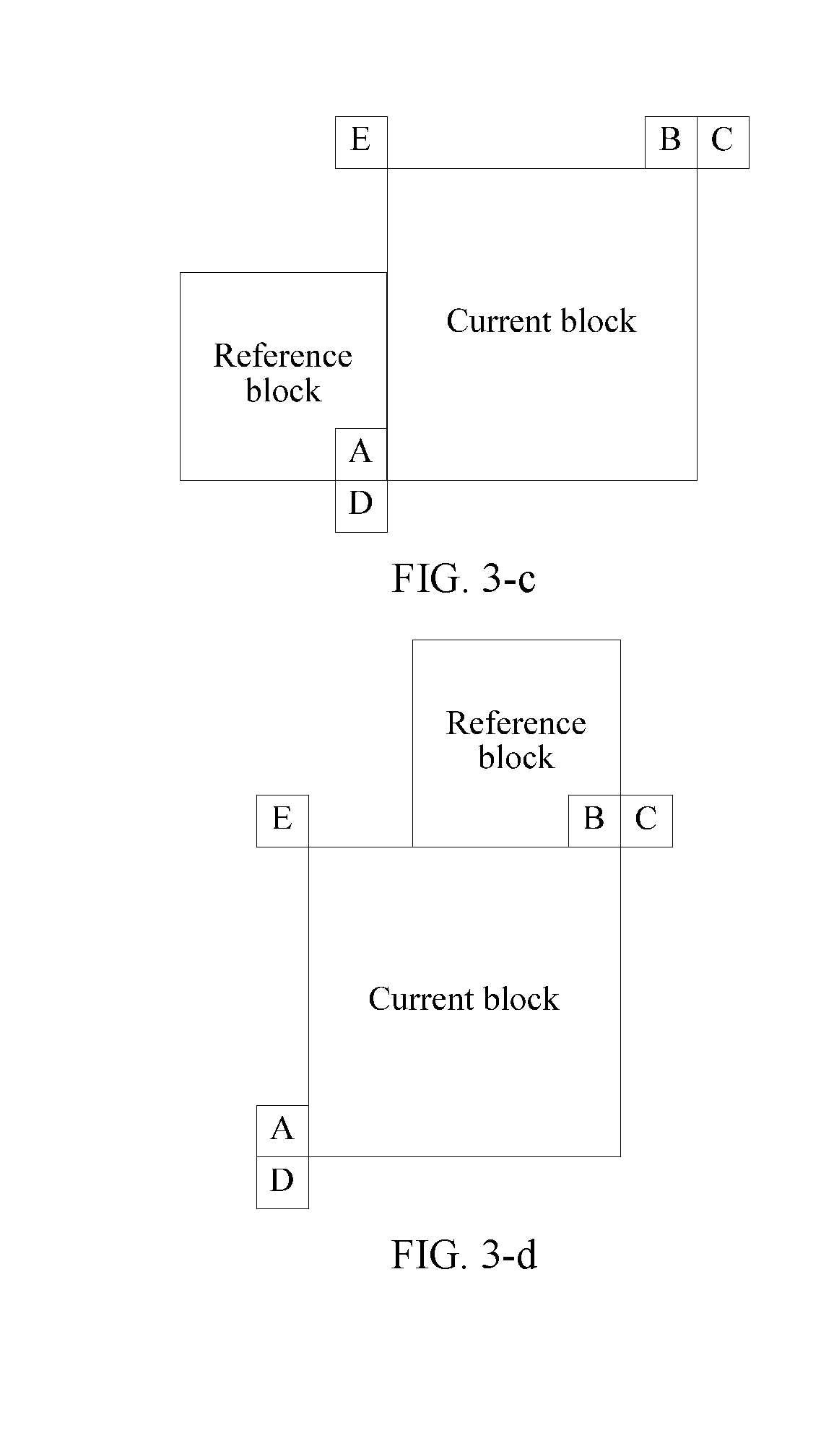
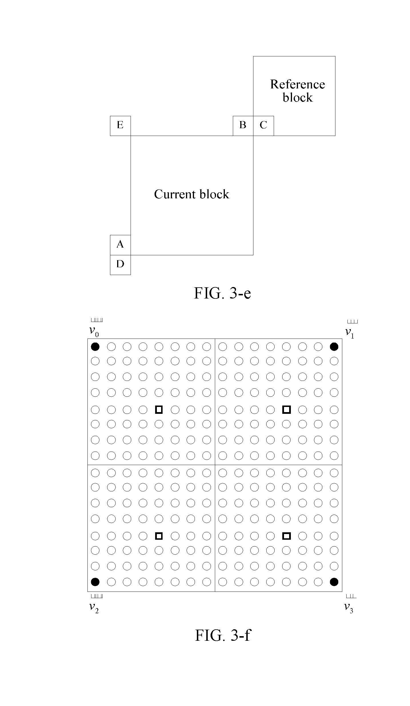
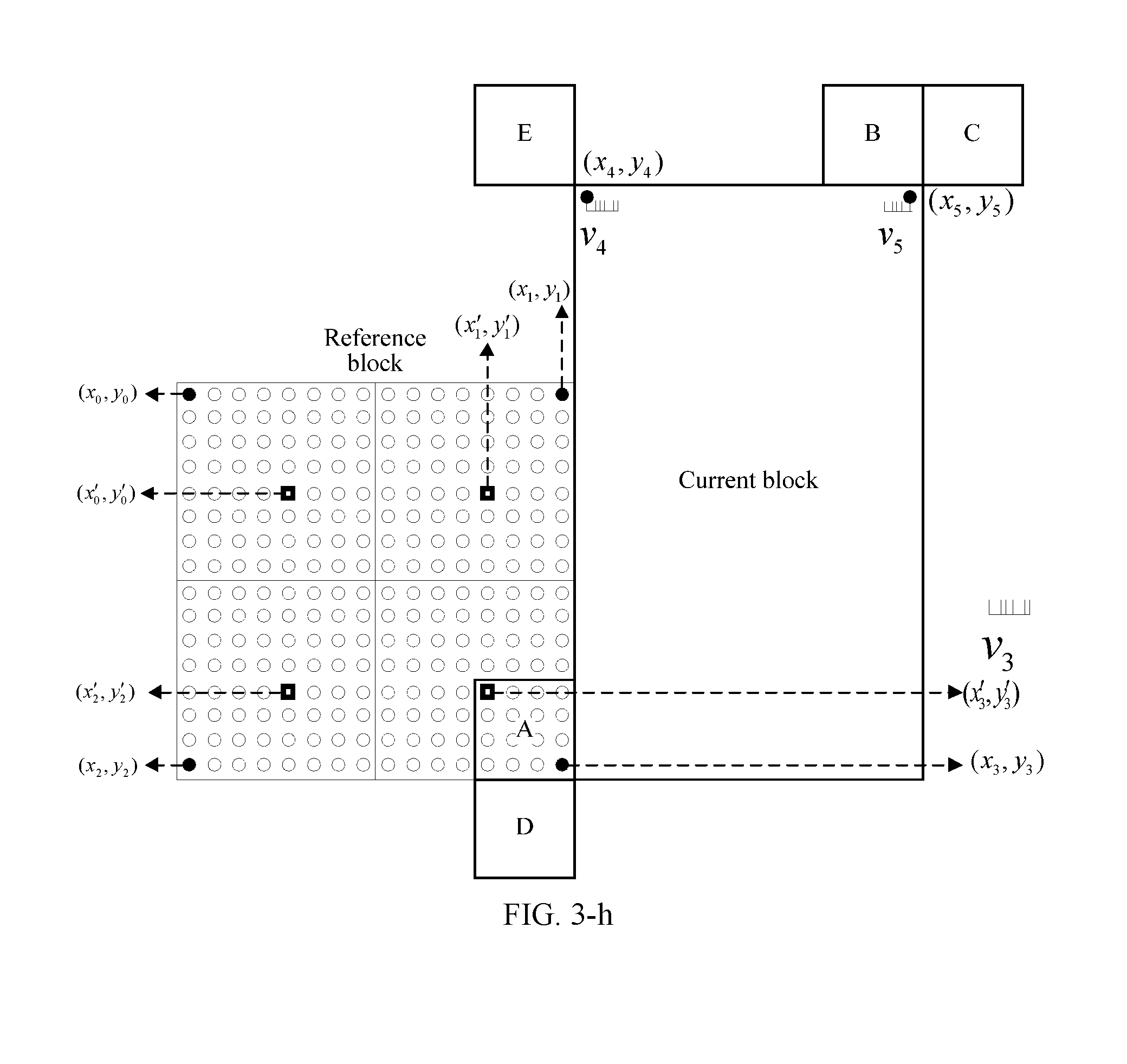
26. The apparatus according to claim 14, wherein the apparatus is applied to a video coding apparatus or a video decoding apparatus.
27. A computer-readable storage medium, wherein the computer-readable storage medium stores a computer program, and the computer program is used to instruct related hardware to perform the method according to claim 1.
Description
CROSS-REFERENCE TO RELATED APPLICATIONS
[0001] This application is a continuation of International Application No. PCT/CN2018/071351 filed on Jan. 4, 2018, which claims priority to Chinese Patent Application No. 201710005575.6, filed on Jan. 4, 2017, the disclosures of the aforementioned applications are incorporated herein by reference in their entireties.
TECHNICAL FIELD
[0002] The present disclosure relates to the video coding and decoding field, and specifically, to a picture prediction method and a related device.
BACKGROUND
[0003] As photoelectric collection technologies develop and high-definition digital video requirements increasingly grow, video data volumes become increasingly large, limited heterogeneous transmission bandwidth and diversified video applications constantly impose a higher requirement on video coding efficiency, and formulation of a high efficiency video coding (HEVC) standard is started as required.
[0004] A basic principle of video coding and compression is to eliminate redundancy as much as possible by using correlation between space domains, time domains, and code words. Currently, a popular practice is using a block-based hybrid video coding framework, and video coding and compression is implemented by performing steps such as prediction (including intra-frame prediction and inter-frame prediction), conversion, quantization, and entropy encoding. This encoding framework shows very strong vitality, and HEVC still uses this block-based hybrid video coding framework.
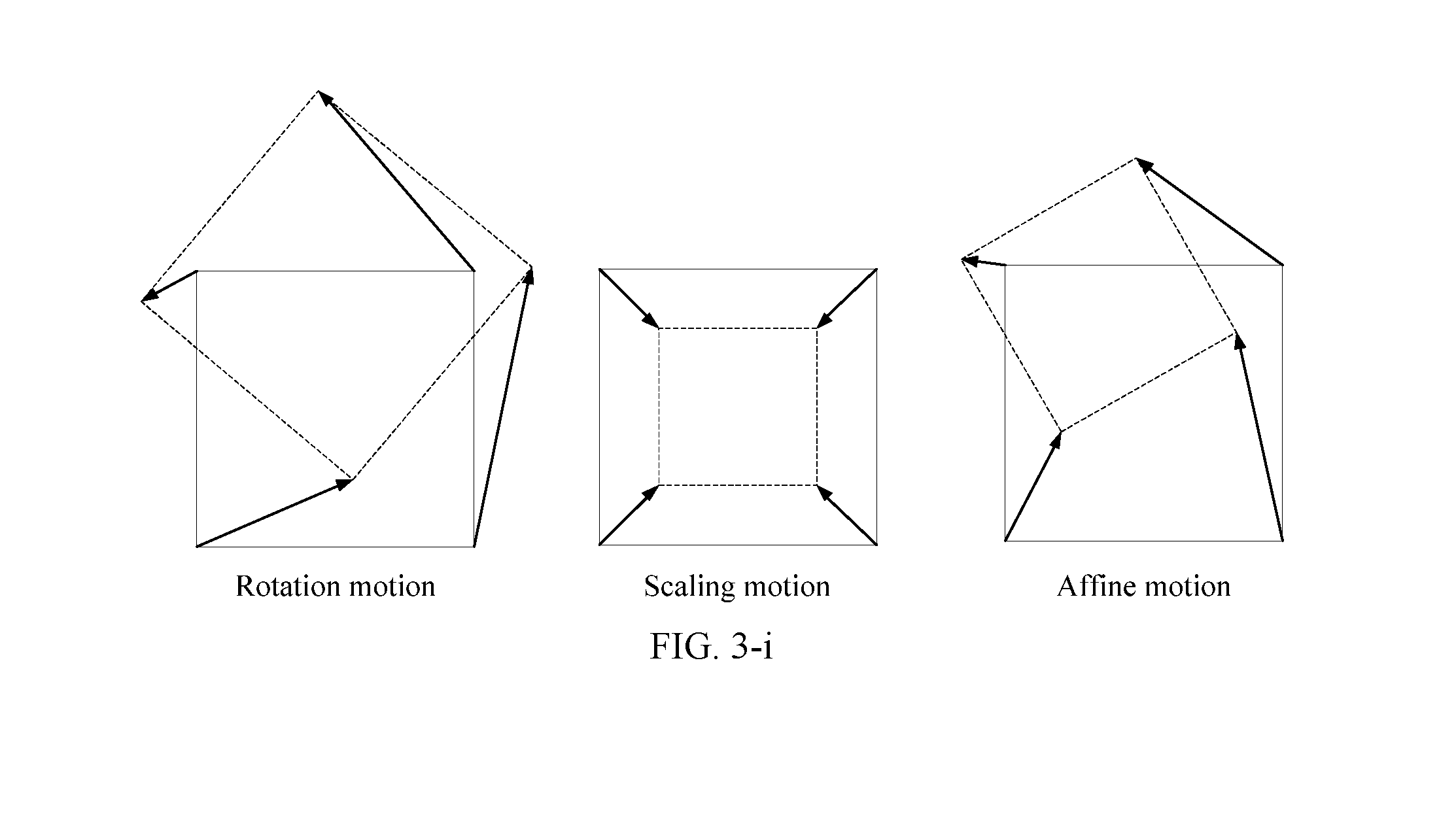
[0005] In various video coding/decoding solutions, motion estimation/motion compensation is a key technology affecting encoding/decoding performance. In many existing video coding/decoding solutions, it is usually assumed that a motion of an object satisfies a translational motion and various parts of the entire object have the same motion. Existing motion estimation/motion compensation algorithms are almost bloc-based motion compensation algorithms based on a translational motion model. Existing inter-frame prediction is mainly block-based motion compensation prediction based on a translational motion model. Some non-translational motion models (for example, an affine motion model) designed for a non-translational motion are gradually provided.
[0006] It is found in practice that in a conventional prediction mechanism based on an affine motion model, precision of predicting a current block by using a reference block is sometimes relatively low. Consequently, it is difficult to satisfy a high-precision prediction requirement in some scenarios.
SUMMARY
[0007] Embodiments of the present disclosure provide a picture prediction method and a related device, to improve precision of predicting a current block by using a reference block.
[0008] According to a first aspect, a picture prediction method is provided. The method includes:
[0009] determining, by a picture prediction apparatus, a reference block of a current block, where the reference block and the current block are spatially adjacent, and the reference block is predicted by using an affine motion model; obtaining location information and motion information of at least two feature points in the reference block, where the at least two feature points are located in subblocks in which at least two control points in the reference block are located, the at least two control points are control points used in the affine motion model used for the reference block (that is, the at least two control points are control points used in the affine motion model used to predict the reference block), and motion information of the subblock in which the feature point is located is obtained based on the motion information of the corresponding feature point (for example, the motion information of the feature point is used as the motion information of the subblock in which the feature point is located); calculating, by the picture prediction apparatus, motion information of each subblock in the current block based on the location information and the motion information of the at least two feature points in the reference block; and performing, by the picture prediction apparatus, motion compensation prediction on each subblock in the current block based on the motion information of each subblock in the current block, to obtain a prediction block of the current block.
[0010] In one embodiment, the motion information is, for example, a motion vector. In one embodiment, the location information is, for example, coordinates.
[0011] In one embodiment, the affine motion model used for the reference block is, for example, the same as or similar to an affine motion model used for the current block. "The affine motion model used for the reference block" is the affine motion model used to predict the reference block. "The affine motion model used for the current block" is an affine motion model used to predict the current block.
[0012] The reference block of the current block may be, for example, a picture block adjacent to an upper left vertex of the current block, a picture block adjacent to a lower left vertex of the current block, a picture block adjacent to an upper right vertex of the current block, or a picture block adjacent to a lower right vertex of the current block. Certainly, the reference block of the current block may alternatively be, for example, another picture block adjacent to the current block.
[0013] As can be learned, in the foregoing technical solution, the motion information of each subblock in the current block is calculated based on the location information and the motion information of the at least two feature points in the current block. In addition, the at least two feature points are located in the subblocks in which the at least two control points in the reference block are located, the at least two control points are the control points used in the affine motion model used to predict the reference block, and the motion information of the subblock in which the feature point is located is obtained based on the motion information of the corresponding feature point. Therefore, the location information and the motion information of the feature point in the reference block that are used to calculate the motion information of each subblock in the current block are matched at a relatively high degree. It is found in practice that this helps improve accuracy of calculating the motion information of each subblock in the current block, thereby improving precision of predicting the current block by using the reference block.
[0014] The picture prediction method provided in this embodiment may be applied to a video coding process or a video decoding process.
[0015] According to a second aspect, a picture prediction apparatus is further provided. The apparatus includes:
[0016] a determining unit configured to determine a reference block of a current block, where the reference block and the current block are spatially adjacent, and the reference block is predicted by using an affine motion model;
[0017] an obtaining unit configured to obtain location information and motion information of at least two feature points in the reference block, where the at least two feature points are located in subblocks in which at least two control points in the reference block are located, the at least two control points are control points used in the affine motion model used for the reference block, and motion information of the subblock in which the feature point is located is obtained based on motion information of the corresponding feature point;
[0018] a calculation unit configured to calculate motion information of each subblock in the current block based on the location information and the motion information of the at least two feature points in the reference block; and
[0019] a prediction unit configured to perform motion compensation prediction on each subblock in the current block based on the motion information of each subblock in the current block, to obtain a prediction block of the current block.
[0020] The picture prediction apparatus provided in this embodiment is applied to a video coding apparatus or a video decoding apparatus. The video coding apparatus or the video decoding apparatus may be any apparatus that needs to output or store a video, for example, a device such as a notebook computer, a tablet computer, a personal computer, a mobile phone, or a video server.
[0021] The video coding apparatus and the video decoding apparatus may perform subblock division based on a same block division manner agreed on. Alternatively, the video coding apparatus may write a block division manner indication to a bitstream, to notify the video decoding apparatus of a block division manner used by the video coding apparatus, so that the video coding apparatus and the video decoding apparatus use the same block division manner.
[0022] With reference to the technical solution according to either of the foregoing aspects, in some embodiments, the feature point is in a central location of the subblock in which the control point in the reference block is located. In other words, the feature point may be a pixel in the central location of the subblock in which the feature point is located. It is found in practice that if motion information (e.g., a motion vector) of the pixel in the central location of the subblock is used as the motion information of the subblock, better prediction precision is desirably obtained.
[0023] With reference to the technical solution according to either of the foregoing aspects, in some embodiments, the location information of the feature point in the reference block is obtained by offsetting location information of the control point in the reference block in the following manner: (x',y')=(x+a,y+b).
[0024] (x,y) are coordinates of a control point in the reference block, (x',y') are coordinates of a feature point in a subblock in which the control point whose coordinates are (x,y) in the reference block is located, a is a horizontal offset, b is a vertical offset, and a and b are not equal to 0.
[0025] With reference to the technical solution according to either of the foregoing aspects, in some embodiments, the at least two control points in the reference block include at least two of an upper left vertex, an upper right vertex, a lower left vertex, and a lower right vertex of the reference block. When location coordinates of the upper left vertex of the reference block are (x.sub.0,y.sub.0), a width of the reference block is w, and a height of the reference block is h,
{ ( x 1 , y 1 ) = ( x 0 + w , y 0 ) ( x 2 , y 2 ) = ( x 0 , y 0 + h ) ( x 3 , y 3 ) = ( x 0 + w , y 0 + h ) , ##EQU00001##
[0026] where (x.sub.1,y.sub.1) are coordinates of the upper right vertex of the reference block, (x.sub.2,y.sub.2) are coordinates of the lower left vertex of the reference block, and (x.sub.3,y.sub.3) are coordinates of the lower right vertex of the reference block.
[0027] For example, in some possible implementations, the at least two feature points may include feature points whose coordinates are respectively (x.sub.0',y.sub.0') and (x.sub.1',y.sub.1') in the reference block, where
{ ( x 0 ' , y 0 ' ) = ( x 0 + N 1 / 2 , y 0 + N 2 / 2 ) ( x 1 ' , y 1 ' ) = ( x 1 - N 1 / 2 , y 1 + N 2 / 2 ) or { ( x 0 ' , y 0 ' ) = ( x 0 + N 1 / 2 , y 0 + N 2 / 2 ) ( x 1 ' , y 1 ' ) = ( x 0 + w - N 1 / 2 , y 0 + N 2 / 2 ) , ##EQU00002##
[0028] where N.sub.1 is a width of the subblock in which the control point in the reference block is located, N.sub.2 is a height of the subblock in which the control point in the reference block is located, (x.sub.0,y.sub.0) are coordinates of a control point in a subblock in which the feature point (x.sub.0',y.sub.0') in the reference block is located, (x.sub.1,y.sub.1) are coordinates of a control point in a subblock in which the feature point (x.sub.1',y.sub.1') in the reference block is located, and w is the width of the reference block.
[0029] For another example, in some possible implementations, the at least two feature points may include feature points whose coordinates are respectively (x.sub.0',y.sub.0'), (x.sub.1',y.sub.1'), and (x.sub.2',y.sub.2') in the reference block, where
{ ( x 0 ' , y 0 ' ) = ( x 0 + N 1 / 2 , y 0 + N 2 / 2 ) ( x 1 ' , y 1 ' ) = ( x 1 - N 1 / 2 , y 1 + N 2 / 2 ) ( x 2 ' , y 2 ' ) = ( x 2 + N 1 / 2 , y 2 - N 2 / 2 ) or { ( x 0 ' , y 0 ' ) = ( x 0 + N 1 / 2 , y 0 + N 2 / 2 ) ( x 1 ' , y 1 ' ) = ( x 0 + w - N 1 / 2 , y 0 + N 2 / 2 ) ( x 2 ' , y 2 ' ) = ( x 0 + N 1 / 2 , y 0 + h - N 2 / 2 ) , ##EQU00003##
[0030] where N.sub.1 is a width of the subblock in which the control point in the reference block is located, N.sub.2 is a height of the subblock in which the control point in the reference block is located, (x.sub.0,y.sub.0) are coordinates of a control point in a subblock in which the feature point (x.sub.0',y.sub.0') in the reference block is located, (x.sub.1,y.sub.1) are coordinates of a control point in a subblock in which the feature point (x.sub.1',y.sub.1') in the reference block is located, (x.sub.2,y.sub.2) are coordinates of a control point in a subblock in which the feature point (x.sub.2',y.sub.2') in the reference block is located, w is the width of the reference block, and h is the height of the reference block.
[0031] For another example, in some possible implementations, the at least two feature points include feature points whose coordinates are respectively (x.sub.0',y.sub.0'), (x.sub.1',y.sub.1'), (x.sub.2',y.sub.2'), and (x.sub.3',y.sub.3') in the reference block, where
{ ( x 0 ' , y 0 ' ) = ( x 0 + N 1 / 2 , y 0 + N 2 / 2 ) ( x 1 ' , y 1 ' ) = ( x 1 - N 1 / 2 , y 1 + N 2 / 2 ) ( x 2 ' , y 2 ' ) = ( x 2 + N 1 / 2 , y 2 - N 2 / 2 ) ( x 3 ' , y 3 ' ) = ( x 3 - N 1 / 2 , y 3 - N 2 / 2 ) or { ( x 0 ' , y 0 ' ) = ( x 0 + N 1 / 2 , y 0 + N 2 / 2 ) ( x 1 ' , y 1 ' ) = ( x 0 + w - N 1 / 2 , y 0 + N 2 / 2 ) ( x 2 ' , y 2 ' ) = ( x 0 + N 1 / 2 , y 0 + h - N 2 / 2 ) ( x 3 ' , y 3 ' ) = ( x 0 + w - N 1 / 2 , y 0 + h - N 2 / 2 ) , ##EQU00004##
[0032] where N.sub.1 is a width of the subblock in which the control point in the reference block is located, N.sub.2 is a height of the subblock in which the control point in the reference block is located, (x.sub.0,y.sub.0) are coordinates of a control point in a subblock in which the feature point (x.sub.0',y.sub.0') in the reference block is located, (x.sub.1,y.sub.1) are coordinates of a control point in a subblock in which the feature point (x.sub.1',y.sub.1') in the reference block is located, (x.sub.2,y.sub.2) are coordinates of a control point in a subblock in which the feature point (x.sub.2',y.sub.2') in the reference block is located, w is the width of the reference block, and h is the height of the reference block.
[0033] In some embodiments, the calculating motion information of each subblock in the current block based on the location information and the motion information of the at least two feature points in the reference block includes: calculating the motion information of each subblock in the current block based on the location information and the motion information of the at least two feature points in the reference block and location information of each subblock in the current block.
[0034] For example, the calculating the motion information of each subblock in the current block based on the location information and the motion information of the at least two feature points in the reference block and location information of each subblock in the current block includes: calculating the motion information of each subblock in the current block with reference to the following formula and based on the location information and the motion information of the at least two feature points in the reference block and the location information of each subblock in the current block:
{ vx = vx 1 - vx 0 x 1 ' - x 0 ' .times. ( x - x 0 ' ) - vy 1 - vy 0 x 1 ' - x 0 ' .times. ( y - y 0 ' ) + vx 0 vy = vy 1 - vy 0 x 1 ' - x 0 ' .times. ( x - x 0 ' ) + vx 1 - vx 0 x 1 ' - x 0 ' .times. ( y - y 0 ' ) + vy 0 or { vx = vx 1 - vx 0 x 1 ' - x 0 ' .times. ( x - x 0 ' ) + vx 2 - vx 0 x 2 ' - x 0 ' .times. ( y - y 0 ' ) + vx 0 vy = vy 1 - vy 0 x 1 ' - x 0 ' .times. ( x - x 0 ' ) + vy 2 - vy 0 y 2 ' - y 0 ' .times. ( y - y 0 ' ) + vy 0 or { vx = vx 1 - vx 0 x 1 ' - x 0 ' .times. ( x - x 0 ' ) + vx 2 - vx 0 y 2 ' - y 0 ' .times. ( y - y 0 ' ) + ( vx 3 + vx 0 ) - ( vx 1 + vx 2 ) ( x 1 ' - x 0 ' ) .times. ( y 2 ' - y 0 ' ) .times. ( x - x 0 ' ) .times. ( y - y 0 ' ) + vx 0 vy = vy 1 - vy 0 x 1 ' - x 0 ' .times. ( x - x 0 ' ) + vy 2 - vy 0 y 2 ' - y 0 ' .times. ( y - y 0 ' ) + ( vy 3 + vy 0 ) - ( vy 1 + vy 2 ) ( x 1 ' - x 0 ' ) .times. ( y 2 ' - y 0 ' ) .times. ( x - x 0 ' ) .times. ( y - y 0 ' ) + vy 0 , ##EQU00005##
[0035] the at least two feature points include the feature points whose coordinates are (x.sub.0',y.sub.0') and (x.sub.1',y.sub.1') in the reference block;
[0036] the at least two feature points include the feature points whose coordinates are (x.sub.0',y.sub.0'), (x.sub.1',y.sub.1'), and (x.sub.2',y.sub.2') in the reference block; or
[0037] the at least two feature points include the feature points whose coordinates are (x.sub.0',y.sub.0'), (x.sub.1',y.sub.1'), (x.sub.2',y.sub.2'), and (x.sub.3',y.sub.3') in the reference block, where
[0038] vx.sub.0 is a horizontal motion vector of the feature point (x.sub.0',y.sub.0'), vy.sub.0 is a vertical motion vector of the feature point (x.sub.0',y.sub.0'); vx.sub.1 is a horizontal motion vector of the feature point (x.sub.1',y.sub.1'), vy.sub.1 is a vertical motion vector of the feature point (x.sub.1',y.sub.1'), vy.sup.2 is a vertical motion vector of the feature point (x.sub.2',y.sub.2'), vx.sub.2 is a horizontal motion vector of the feature point (x.sub.2',y.sub.2'), vy.sub.3 is a vertical motion vector of the feature point (x.sub.3',y.sub.3'), and vx.sub.3 is a horizontal motion vector of the feature point (x.sub.3,y.sub.3'); and
[0039] vx is a horizontal motion vector of a subblock whose coordinates are (x,y) in the current block, and vy is a vertical motion vector of the subblock whose coordinates are (x,y) in the current block.
[0040] In some embodiments, the calculating motion information of each subblock in the current block based on the location information and the motion information of the at least two feature points in the reference block includes: calculating, based on the location information and the motion information of the at least two feature points in the reference block, motion information of at least two control points used in an affine motion model used for the current block; and calculating the motion information of each subblock in the current block based on location information of each subblock in the current block and the motion information and location information of the at least two control points used in the affine motion model used for the current block.
[0041] The at least two control points used in the affine motion model used for the current block may include, for example, at least two of the upper left vertex, the lower left vertex, the upper right vertex, and the lower right vertex of the current block.
[0042] For example, the calculating, based on the location information and the motion information of the at least two feature points in the reference block, the motion information of at least two control points used in an affine motion model used for the current block includes: calculating, with reference to the following formula and based on the location information and the motion information of the at least two feature points in the reference block, the motion information of the at least two control points used in the affine motion model used for the current block:
{ vx 4 = vx 1 - vx 0 x 1 ' - x 0 ' .times. ( x 4 - x 0 ' ) - vy 1 - vy 0 x 1 ' - x 0 ' .times. ( y 4 - y 0 ' ) + vx 0 vy 4 = vy 1 - vy 0 x 1 ' - x 0 ' .times. ( x 4 - x 0 ' ) + vx 1 - vx 0 x 1 ' - x 0 ' .times. ( y 4 - y 0 ' ) + vy 0 { vx 5 = vx 1 - vx 0 x 1 ' - x 0 ' .times. ( x 5 - x 0 ' ) - vy 1 - vy 0 x 1 ' - x 0 ' .times. ( y 5 - y 0 ' ) + vx 0 vy 5 = vy 1 - vy 0 x 1 ' - x 0 ' .times. ( x 5 - x 0 ' ) + vx 1 - vx 0 x 1 ' - x 0 ' .times. ( y 5 - y 0 ' ) + vy 0 or { vx 4 = vx 1 - vx 0 x 1 ' - x 0 ' .times. ( x 4 - x 0 ' ) + vx 2 - vx 0 x 2 ' - x 0 ' .times. ( y 4 - y 0 ' ) + vx 0 vy 4 = vy 1 - vy 0 x 1 ' - x 0 ' .times. ( x 4 - x 0 ' ) + vy 2 - y 0 y 2 ' - y 0 ' .times. ( y 4 - y 0 ' ) + vy 0 { vx 5 = vx 1 - vx 0 x 1 ' - x 0 ' .times. ( x 5 - x 0 ' ) + vx 2 - vx 0 x 2 ' - x 0 ' .times. ( y 5 - y 0 ' ) + vx 0 vy 5 = vy 1 - vy 0 x 1 ' - x 0 ' .times. ( x 5 - x 0 ' ) + vy 2 - vy 0 y 2 ' - y 0 ' .times. ( y 5 - y 0 ' ) + vy 0 { vx 6 = vx 1 - vx 0 x 1 ' - x 0 ' .times. ( x 6 - x 0 ' ) + vx 2 - vx 0 x 2 ' - x 0 ' .times. ( y 6 - y 0 ' ) + vx 0 vy 6 = vy 1 - vy 0 x 1 ' - x 0 ' .times. ( x 6 - x 0 ' ) + vy 2 - vy 0 y 2 ' - y 0 ' .times. ( y 6 - y 0 ' ) + vy 0 or { vx 4 = vx 1 - vx 0 x 1 ' - x 0 ' .times. ( x 4 - x 0 ' ) + vx 2 - vx 0 x 2 ' - x 0 ' .times. ( y 4 - y 0 ' ) + ( vx 3 + vx 0 ) - ( vx 1 + vx 2 ) ( x 1 ' - x 0 ' ) .times. ( y 2 ' - y 0 ' ) .times. ( x 4 - x 0 ' ) .times. ( y 4 - y 0 ' ) + vx 0 vy 4 = vy 1 - vy 0 x 1 ' - x 0 ' .times. ( x 4 - x 0 ' ) + vy 2 - vy 0 y 2 ' - y 0 ' .times. ( y 4 - y 0 ' ) + ( vy 3 + vy 0 ) - ( vy 1 + vy 2 ) ( x 1 ' - x 0 ' ) .times. ( y 2 ' - y 0 ' ) .times. ( x 4 - x 0 ' ) .times. ( y 4 - y 0 ' ) + vy 0 { vx 5 = vx 1 - vx 0 x 1 ' - x 0 ' .times. ( x 5 - x 0 ' ) + vx 2 - vx 0 x 2 ' - x 0 ' .times. ( y 5 - y 0 ' ) + ( vx 3 + vx 0 ) - ( vx 1 + vx 2 ) ( x 1 ' - x 0 ' ) .times. ( y 2 ' - y 0 ' ) .times. ( x 5 - x 0 ' ) .times. ( y 5 - y 0 ' ) + vx 0 vy 5 = vy 1 - vy 0 x 1 ' - x 0 ' .times. ( x 5 - x 0 ' ) + vy 2 - vy 0 y 2 ' - y 0 ' .times. ( y 5 - y 0 ' ) + ( vy 3 + vy 0 ) - ( vy 1 + vy 2 ) ( x 1 ' - x 0 ' ) .times. ( y 2 ' - y 0 ' ) .times. ( x 5 - x 0 ' ) .times. ( y 5 - y 0 ' ) + vy 0 { vx 6 = vx 1 - vx 0 x 1 ' - x 0 ' .times. ( x 6 - x 0 ' ) + vx 2 - vx 0 x 2 ' - x 0 ' .times. ( y 6 - y 0 ' ) + ( vx 3 + vx 0 ) - ( vx 1 + vx 2 ) ( x 1 ' - x 0 ' ) .times. ( y 2 ' - y 0 ' ) .times. ( x 6 - x 0 ' ) .times. ( y 6 - y 0 ' ) + vx 0 vy 6 = vy 1 - vy 0 x 1 ' - x 0 ' .times. ( x 6 - x 0 ' ) + vy 2 - vy 0 y 2 ' - y 0 ' .times. ( y 6 - y 0 ' ) + ( vy 3 + vy 0 ) - ( vy 1 + vy 2 ) ( x 1 ' - x 0 ' ) .times. ( y 2 ' - y 0 ' ) .times. ( x 6 - x 0 ' ) .times. ( y 6 - y 0 ' ) + vy 0 { vx 7 = vx 1 - vx 0 x 1 ' - x 0 ' .times. ( x 7 - x 0 ' ) + vx 2 - vx 0 x 2 ' - x 0 ' .times. ( y 7 - y 0 ' ) + ( vx 3 + vx 0 ) - ( vx 1 + vx 2 ) ( x 1 ' - x 0 ' ) .times. ( y 2 ' - y 0 ' ) .times. ( x 7 - x 0 ' ) .times. ( y 7 - y 0 ' ) + vx 0 vy 7 = vy 1 - vy 0 x 1 ' - x 0 ' .times. ( x 7 - x 0 ' ) + vy 2 - vy 0 y 2 ' - y 0 ' .times. ( y 7 - y 0 ' ) + ( vy 3 + vy 0 ) - ( vy 1 + vy 2 ) ( x 1 ' - x 0 ' ) .times. ( y 2 ' - y 0 ' ) .times. ( x 7 - x 0 ' ) .times. ( y 7 - y 0 ' ) + vy 0 , ##EQU00006##
[0043] where the at least two feature points include the feature points whose coordinates are (x.sub.0',y.sub.0') and (x.sub.1',y.sub.1') in the reference block;
[0044] the at least two feature points include the feature points whose coordinates are (x.sub.0',y.sub.0'), (x.sub.1',y.sub.1'), and (x.sub.2',y.sub.2') in the reference block; or
[0045] the at least two feature points include the feature points whose coordinates are (x.sub.0',y.sub.0'), (x.sub.1',y.sub.1'), (x.sub.2',y.sub.2'), and (x.sub.3',y.sub.3') in the reference block, where
[0046] the at least two control points used in the affine motion model used for the current block include control points whose coordinates are respectively (x.sub.4,y.sub.4) and (x.sub.5,y.sub.5) in the current block; the at least two control points used in the affine motion model used for the current block include control points whose coordinates are respectively (x.sub.4,y.sub.4), (x.sub.5,y.sub.5), and (x.sup.6,y.sup.6) in the current block; or the at least two control points used in the affine motion model used for the current block include control points whose coordinates are respectively (x.sub.4,y.sub.4), (x.sub.5,y.sub.5), (x.sub.6,y.sub.6) and (x.sub.7,y.sub.7) in the current block; and
[0047] vx.sub.4 is a horizontal motion vector of the control point (x.sub.4,y.sub.4), vy.sup.4 is a vertical motion vector of the control point (x.sub.4,y.sub.4); vx.sub.5 is a horizontal motion vector of the control point (x.sub.5,y.sub.5) vy.sup.5 is a vertical motion vector of the control point (x.sub.5,y.sub.5), vx.sub.6 is a horizontal motion vector of the control point (x.sub.6,y.sub.6), vy.sub.6 is a vertical motion vector of the control point (x.sub.6,y.sub.6), vx.sub.7 is a horizontal motion vector of the control point (x.sub.7,y.sub.7), and vy.sub.7 is a vertical motion vector of the control point (x.sub.7,y.sub.7).
[0048] For example, the calculating the motion information of each subblock in the current block based on location information of each subblock in the current block and the motion information and location information of the at least two control points used in the affine motion model used for the current block includes: calculating the motion information of each subblock in the current block with reference to the following formula and based on the location information of each subblock in the current block and the motion information and the location information of the at least two control points used in the affine motion model used for the current block:
{ vx = vx 5 - vx 4 x 5 - x 4 .times. ( x - x 4 ) - vy 5 - vy 4 x 5 - x 4 .times. ( y - y 4 ) + vx 4 vy = vy 5 - vy 4 x 5 - x 4 .times. ( x - x 4 ) + vx 1 - vx 0 x 5 - x 4 .times. ( y - y 4 ) + vy 4 or { vx = vx 5 - vx 4 x 5 - x 4 .times. ( x - x 4 ) + vx 6 - vx 4 x 6 - x 4 .times. ( y - y 4 ) + vx 4 vy = vy 5 - vy 4 x 5 - x 4 .times. ( x - x 4 ) + vy 6 - vy 4 x 6 - x 4 .times. ( y - y 4 ) + vy 4 or { vx = vx 5 - vx 4 x 5 - x 4 .times. ( x - x 4 ) + vx 6 - vx 4 y 6 - y 4 .times. ( y - y 4 ) + ( vx 7 + vx 4 ) - ( vx 5 + vx 6 ) ( x 5 - x 4 ) .times. ( y 6 - y 4 ) .times. ( x - x 4 ) .times. ( y - y 4 ) + vx 4 vy = vy 5 - vy 4 x 5 - x 4 .times. ( x - x 4 ) + vy 6 - vy 4 y 6 - y 4 .times. ( y - y 4 ) + ( vy 7 + vy 4 ) - ( vy 5 + vy 6 ) ( x 5 - x 4 ) .times. ( y 6 - y 4 ) .times. ( x - x 4 ) .times. ( y - y 4 ) + vy 4 , ##EQU00007##
[0049] where vx is a horizontal motion vector of a subblock whose coordinates are (x,y) in the current block, and vy is a vertical motion vector of the subblock whose coordinates are (x,y) in the current block.
[0050] According to a third aspect, a picture prediction apparatus is further provided. The apparatus includes: a processor and a storage component coupled to each other. The processor is configured to invoke code stored in the memory/storage component, to perform some or all steps in any picture prediction method according to the embodiments of the present disclosure.
[0051] According to a fourth aspect, a video system is provided. The system includes: a video coding apparatus and a video decoding apparatus. The video coding apparatus or the video decoding apparatus is configured to perform some or all steps in any picture prediction method according to the embodiments of the present disclosure.
[0052] In addition, according to a fifth aspect, a computer-readable storage medium is provided. The computer-readable storage medium stores program code. The program code includes an instruction used to perform some or all steps in any picture prediction method according to the embodiments of the present disclosure.
[0053] In addition, according to a sixth aspect, a computer program product is provided. When the computer program product runs on a computer, the computer is enabled to perform some or all steps in any picture prediction method according to the embodiments of the present disclosure.
BRIEF DESCRIPTION OF DRAWINGS
[0054] To describe the technical solutions in the embodiments of the present disclosure more clearly, the following briefly describes the accompanying drawings required for describing the embodiments. Apparently, the accompanying drawings in the following description show merely some embodiments of the present disclosure, and a person of ordinary skill in the art may derive other drawings from these accompanying drawings without creative efforts.
[0055] FIG. 1-a and FIG. 1-b are several schematic diagrams of dividing a picture block according to one embodiment;
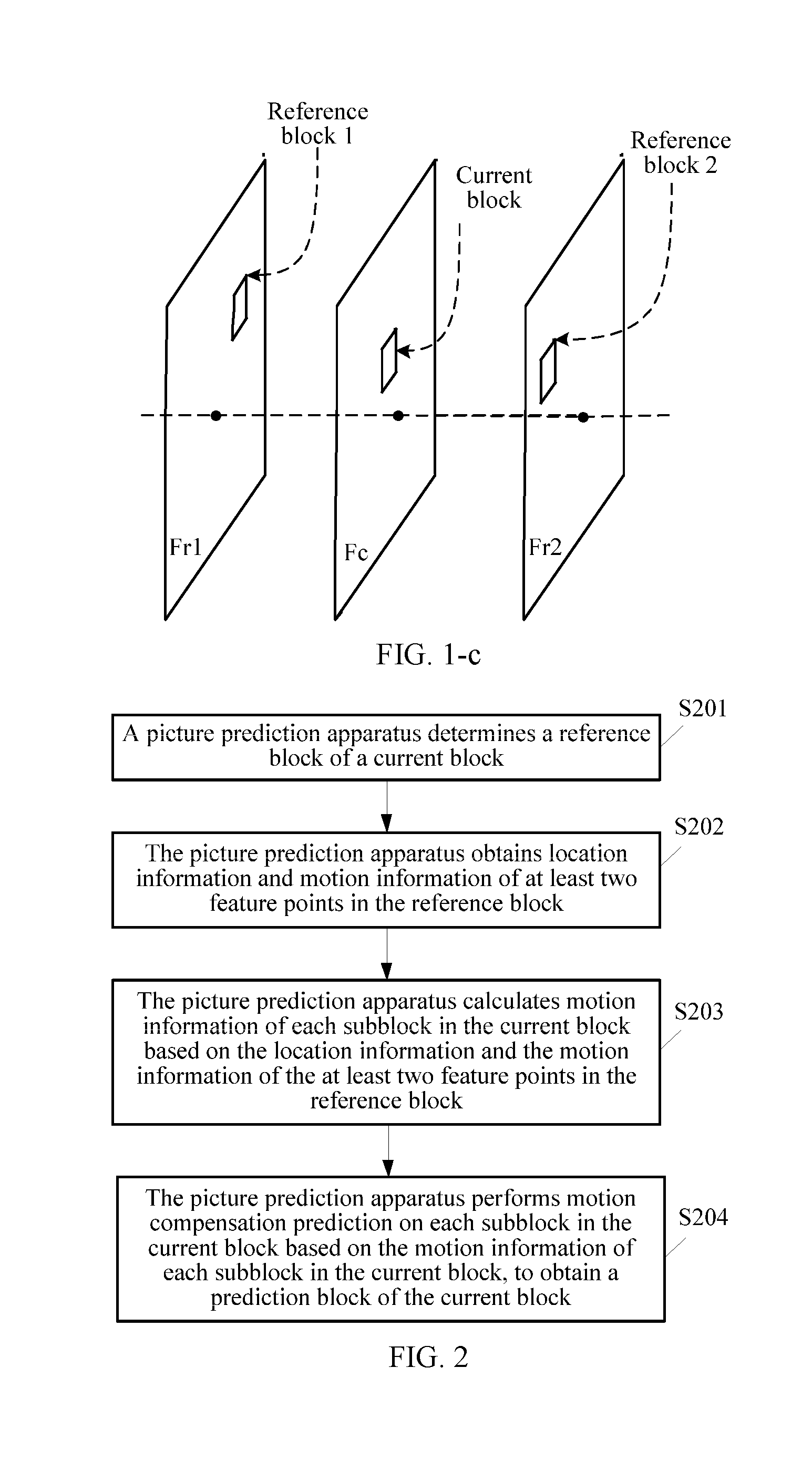
[0056] FIG. 1-c is a schematic diagram of inter-frame prediction according to one embodiment;
[0057] FIG. 2 is a schematic flowchart of a picture prediction method according to one embodiment;
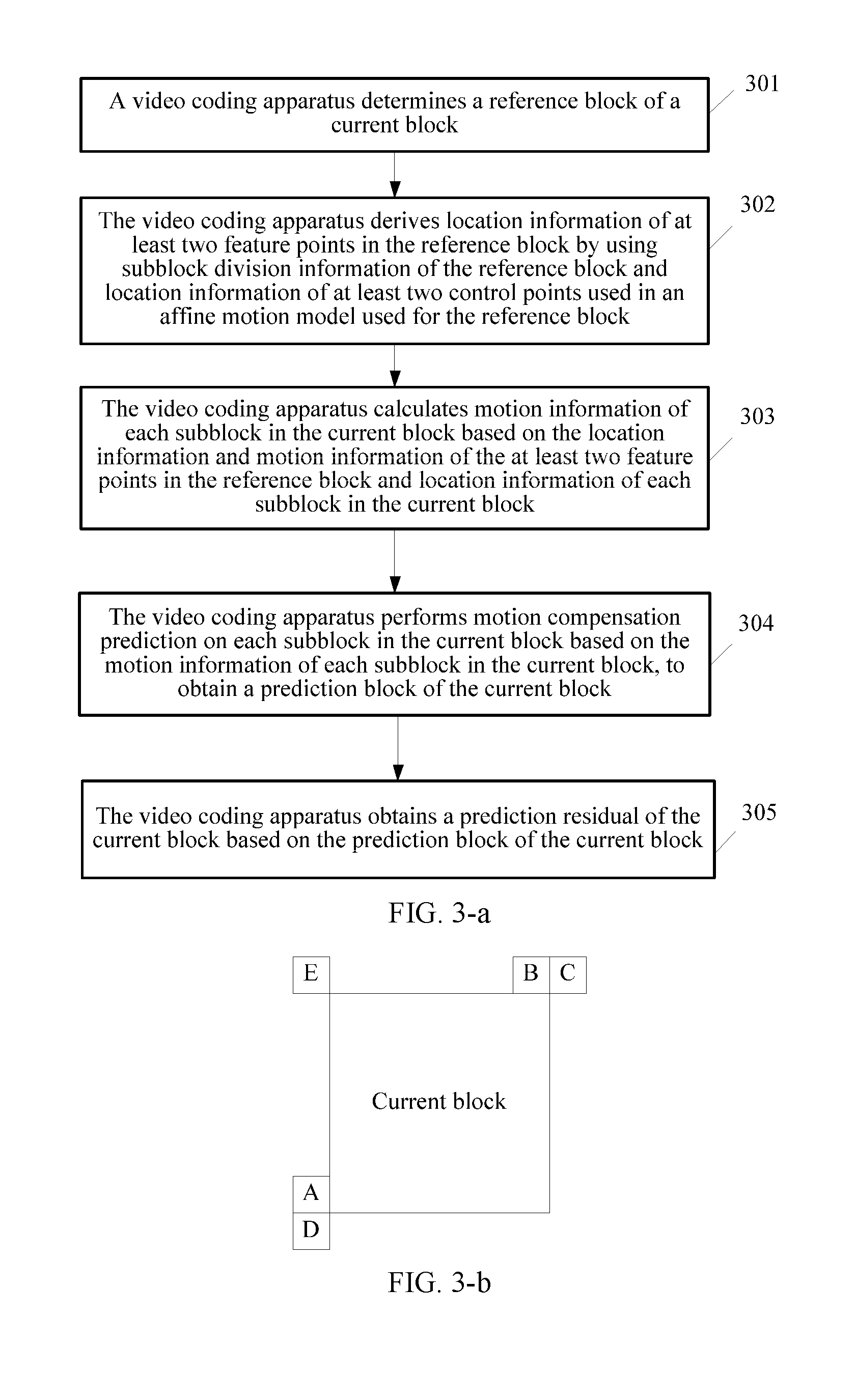
[0058] FIG. 3-a is a schematic flowchart of another picture prediction method according to one embodiment;
[0059] FIG. 3-b is a schematic diagram of a possible location of a reference block according to one embodiment;
[0060] FIG. 3-c to FIG. 3-e are schematic diagrams of reference blocks according to one embodiment;
[0061] FIG. 3-f and FIG. 3-g are schematic diagrams of subblock division of reference blocks according to one embodiment;
[0062] FIG. 3-h is a schematic diagram of a possible positional relationship between a control point and a feature point in a reference block according to one embodiment;
[0063] FIG. 3-i is a schematic diagram of several non-translational motions according to one embodiment;
[0064] FIG. 4 is a schematic flowchart of another picture prediction method according to one embodiment;
[0065] FIG. 5 is a schematic flowchart of another picture prediction method according to one embodiment;
[0066] FIG. 6 is a schematic flowchart of another picture prediction method according to one embodiment;
[0067] FIG. 7 is a schematic diagram of a picture prediction apparatus according to one embodiment;
[0068] FIG. 8 is a schematic diagram of another picture prediction apparatus according to one embodiment;
[0069] FIG. 9-A is a schematic diagram of a video encoder according to one embodiment;
[0070] FIG. 9-B is a schematic diagram of a video decoder according to one embodiment;
[0071] FIG. 10 is a schematic block diagram of an electronic apparatus according to one embodiment;
[0072] FIG. 11 is another schematic block diagram of an electronic apparatus according to one embodiment;
[0073] FIG. 12 is a schematic structural diagram of a television application according to one embodiment; and
[0074] FIG. 13 is a schematic structural diagram of a mobile phone application according to one embodiment.
DESCRIPTION OF EMBODIMENTS
[0075] The embodiments of the present disclosure provide a picture prediction method and a related device.
[0076] In the specification, claims, and accompanying drawings of the present disclosure, the terms "first", "second", "third", and so on are intended to distinguish between different objects but do not indicate a particular order. In addition, the terms "including", "having", or any other variant thereof, are intended to cover non-exclusive inclusion. For example, a process, a method, a system, a product, or a device that includes a series of steps or units is not limited to the listed steps or units, but optionally further includes an unlisted step or unit, or optionally further includes another inherent step or unit of the process, the method, the product, or the device.
[0077] The following first briefly describes some concepts that may be mentioned in the embodiments of the present disclosure.
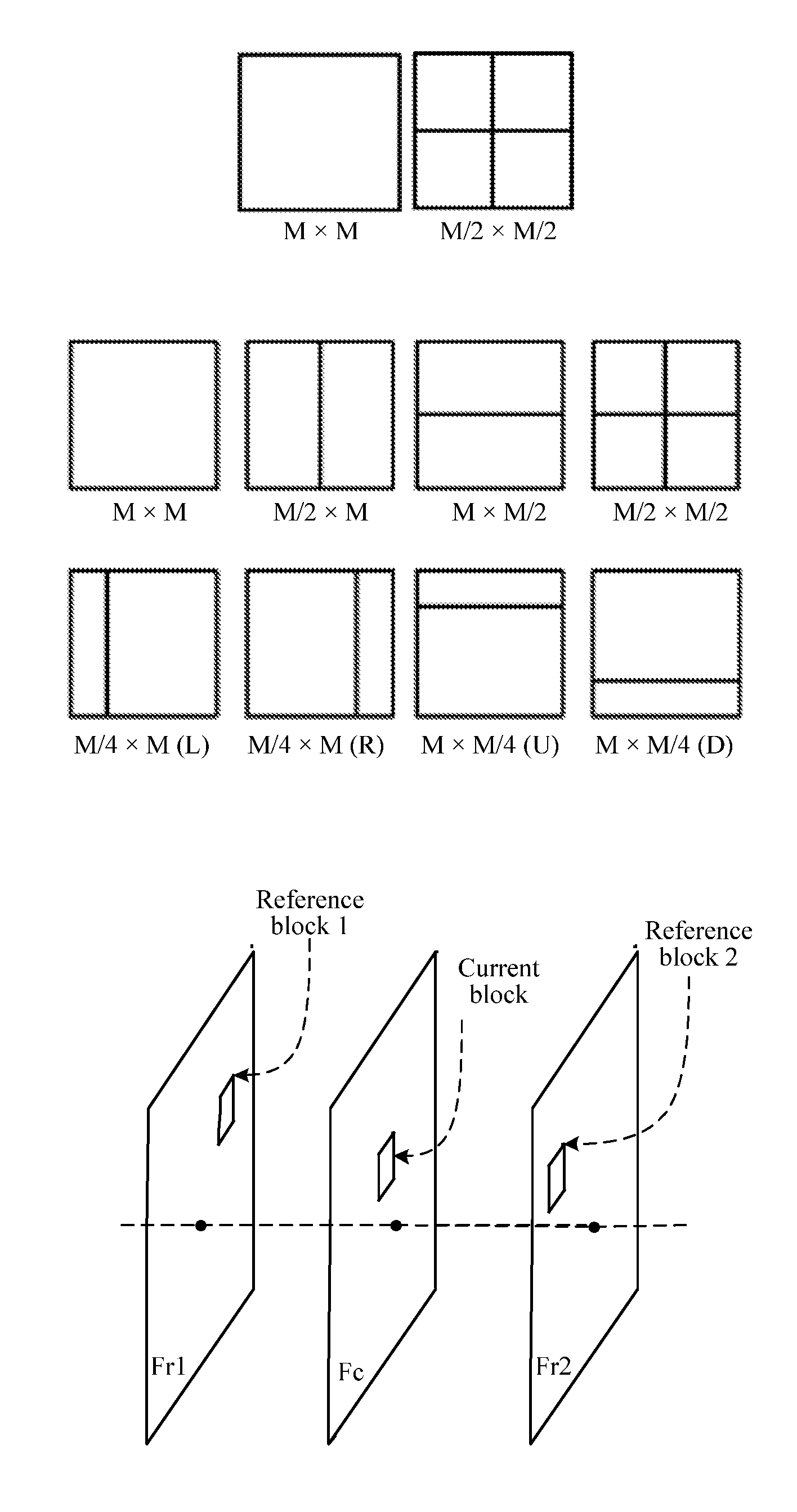
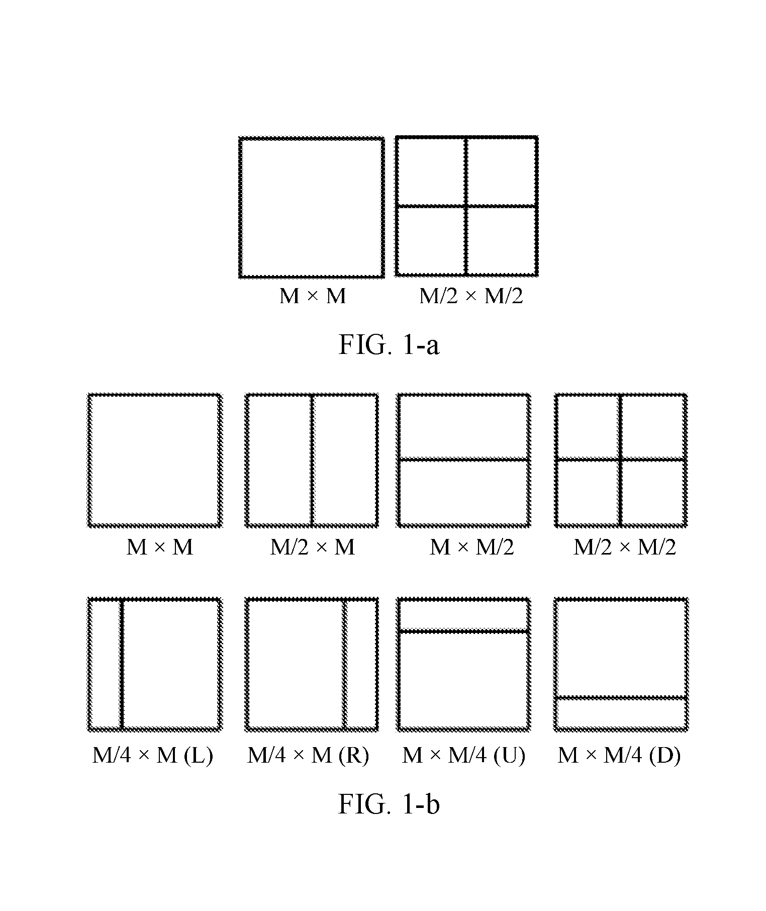
[0078] In most encoding frameworks, a video sequence includes a series of pictures, the picture is further divided into slices, and the slice is further divided into blocks. Video coding is performed on a per-block basis, and encoding processing may be performed from an upper left corner of a picture row by row from left to right and from top to bottom. In some new video coding standards, the concept of block is further extended. In the H.264 standard, there is a macroblock (MB), and the MB may be further divided into a plurality of prediction blocks that may be used for predictive coding. In the HEVC standard, basic concepts such as a coding unit (CU), a prediction unit (PU), and a transform unit (TU) are used, a plurality of units are obtained by division based on functions, and a new tree-based structure is used for description. For example, the CU may be divided into smaller CUs based on a quadtree, and the smaller CU may continue to be divided to form a quadtree structure. The PU and the TU also have a similar tree structure. All the CU, the PU, and the TU essentially belong to the concept of block. The CU is similar to a macroblock MB or an encoding block and is a basic unit for dividing and encoding an encoding picture. The PU may correspond to a prediction block and is a basic unit for predictive coding. The CU is further divided into a plurality of PUs based on a division mode. The TU may correspond to a transformation block and is a basic unit for transforming a prediction residual. In the High Efficiency Video Coding (HEVC) standard, the CU, the PU, and the TU may be collectively referred to as a coding tree block (CTB) or the like.
[0079] In the HEVC standard, sizes of coding units may include four levels: 64.times.64, 32.times.32, 16.times.16, and 8.times.8, and a coding unit at each level may be divided into prediction units with different sizes based on intra-frame prediction and inter-frame prediction. For example, as shown in FIG. 1-a and FIG. 1-b, FIG. 1-a shows an example of a prediction unit division manner corresponding to intra-frame prediction, and FIG. 1-b shows an example of several prediction unit division manners corresponding to inter-frame prediction. FIG. 1-c is a schematic diagram of inter-frame prediction. Existing inter-frame prediction is mainly block-based motion compensation prediction based on a translational motion model. Some non-translational motion models (for example, an affine motion model) designed for a non-translational motion are also gradually provided. FIG. 3-i shows examples of non-translational motion manners such as a rotation motion, a scaling motion, and an affine motion.
[0080] In a development and evolution process of video coding technologies, video coding experts in the art strive to improve encoding efficiency by using time and spatial correlation between adjacent encoding blocks/decoding blocks with various methods. For example, in the H264/advanced video coding (AVC) standard, skip mode encoding and direct mode encoding become effective tools for improving encoding efficiency. A block using these two encoding modes at a low bit rate may usually occupy more than half of an entire encoding sequence. When the skip mode is used for encoding, a skip mode tag is transferred in a bitstream, a motion vector of a current picture block may be derived by using a surrounding motion vector, and a value of a reference block is directly copied as a reconstruction value of the current picture block based on the motion vector. When the direct mode is used for encoding, an encoder may derive a motion vector of a current picture block by using a surrounding motion vector, directly copy a value of a reference block as a predictor of the current picture block based on the motion vector, and encode and predict the current picture block on an encoder side by using the predictor.
[0081] The following continues to discuss technical solutions in the embodiments of the present disclosure.
[0082] The following first describes a picture prediction method provided in the embodiments of the present disclosure. The picture prediction method provided in the embodiments of the present disclosure is performed by a video coding apparatus or a video decoding apparatus. The video coding apparatus or the video decoding apparatus may be any apparatus that needs to output or store a video, for example, a device such as a notebook computer, a tablet computer, a personal computer, a mobile phone, or a video server.
[0083] FIG. 2 is a schematic flowchart of a picture prediction method according to one embodiment. As shown in the example in FIG. 2, the picture prediction method may include:
[0084] S201: A picture prediction apparatus determines a reference block of a current block.
[0085] The reference block (that is, a reference picture block) and the current block (that is, a current picture block) are spatially adjacent. The reference block is predicted (e.g., motion compensation prediction) by using an affine motion model. For example, on an encoder side or a decoder side, a picture block may be selected as the reference block of the current block based on a preset selection policy from blocks spatially adjacent to the current block.
[0086] The reference block of the current block may be, for example, a picture block adjacent to an upper left vertex of the current block, a picture block adjacent to a lower left vertex of the current block, a picture block adjacent to an upper right vertex of the current block, or a picture block adjacent to a lower right vertex of the current block. Certainly, the reference block of the current block may alternatively be, for example, another picture block adjacent to the current block.
[0087] S202: The picture prediction apparatus obtains location information and motion information of at least two feature points in the reference block.
[0088] The at least two feature points are located in subblocks in which at least two control points in the reference block are located. The at least two control points are control points used in the affine motion model used for the reference block. Motion information of the subblock in which the feature point is located is obtained based on the motion information of the corresponding feature point (for example, the motion information of the feature point is used as the motion information of the subblock in which the feature point is located).
[0089] It may be understood that the at least two feature points may be, for example, two, three, four, or another quantity of feature points.
[0090] It may be understood that the at least two control points may be, for example, two, three, four, or another quantity of control points.
[0091] For example, the control points used in the affine motion model used to predict the reference block may include at least two of an upper left vertex, a lower left vertex, an upper right vertex, and a lower right vertex of the reference block. When location coordinates of the upper left vertex of the reference block are (x.sub.0,y.sub.0), a width of the reference block is w, and a height of the reference block is h,
{ ( x 1 , y 1 ) = ( x 0 + w , y 0 ) ( x 2 , y 2 ) = ( x 0 , y 0 + h ) ( x 3 , y 3 ) = ( x 0 + w , y 0 + h ) , ##EQU00008##
[0092] where (x.sub.1',y.sub.1') are coordinates of the upper right vertex of the reference block, (x.sub.2,y.sub.2) are coordinates of the lower left vertex of the reference block, and (x.sub.3,y.sub.3) are coordinates of the lower right vertex of the reference block.
[0093] For example, the feature point may be in a central location of the subblock in which the control point in the reference block is located. In other words, the feature point may be a pixel in the central location of the subblock in which the feature point is located. It is found in practice that if motion information (a motion vector) of the pixel in the central location of the subblock is used as the motion information of the subblock, better prediction precision is desirably obtained.
[0094] For example, assuming that the control points used in the affine motion model used to predict the reference block include the upper left vertex, the lower left vertex, and the upper right vertex, the at least two feature points in the reference block, for example, may include at least two of the following pixels: a pixel in a central location of a subblock in which the upper left vertex of the reference block is located, a pixel in a central location of a subblock in which the lower left vertex is located, and a pixel in a central location of a subblock in which the upper right vertex is located.
[0095] In one embodiment, the motion information is, for example, a motion vector. In one embodiment, the location information is, for example, coordinates.
[0096] In one embodiment, the affine motion model used to predict the reference block is, for example, the same as or similar to an affine motion model used to predict the current block.
[0097] The location information of the at least two feature points (the at least two feature points are, for example, two, three, or four feature points) used in the affine motion model used for the reference block may be obtained by offsetting location information of the control points in the reference block in the following manner: (x',y')=(x+a,y+b). (x,y) are coordinates of a control point in the reference block (x is a horizontal coordinate and y is a vertical coordinate), (x',y') are coordinates of a feature point corresponding to the control point whose coordinates are (x,y) in the reference block (x' is a horizontal coordinate and y' is a vertical coordinate), a is a horizontal offset, b is a vertical offset, and a and b are not equal to 0.
[0098] For example, a may be equal to 1, 2, 3, 4, 5, 6, 7, -1, -2, -3, -4, -5, or another value.
[0099] For example, b may be equal to 1, 2, 3, 4, 5, 6, 7, -1, -2, -3, -4, -5, or another value.
[0100] S203: The picture prediction apparatus calculates motion information of each subblock in the current block based on the location information and the motion information of the at least two feature points in the reference block.
[0101] For example, the calculating motion information of each subblock in the current block based on the location information and the motion information of the at least two feature points in the reference block includes: calculating the motion information of each subblock in the current block based on the location information and the motion information of the at least two feature points in the reference block and location information of each subblock in the current block.
[0102] For another example, the calculating motion information of each subblock in the current block based on the location information and the motion information of the at least two feature points in the reference block includes: calculating, based on the location information and the motion information of the at least two feature points in the reference block, motion information of at least two control points used in an affine motion model used for the current block; and calculating the motion information of each subblock in the current block based on location information of each subblock in the current block and the motion information and location information of the at least two control points used in the affine motion model used for the current block.
[0103] S204: The picture prediction apparatus performs motion compensation prediction on each subblock in the current block based on the motion information of each subblock in the current block, to obtain a prediction block of the current block.
[0104] As can be learned from the foregoing, in the solution provided in this embodiment, the motion information of each subblock in the current block is calculated based on the location information and the motion information of the at least two feature points in the current block. In addition, the at least two feature points are located in the subblocks in which the at least two control points in the reference block are located, the at least two control points are the control points used in the affine motion model used to predict the reference block, and the motion information of the subblock in which the feature point is located is obtained based on the motion information of the corresponding feature point. Therefore, the location information and the motion information of the feature point in the reference block that are used to calculate the motion information of each subblock in the current block are matched at a relatively high degree. It is found in practice that this helps improve accuracy of calculating the motion information of each subblock in the current block, thereby improving precision of predicting the current block by using the reference block.
[0105] For example, if the motion information of each subblock in the current block is calculated based on the motion information of the feature point in the reference block and the location information of the control point, because the motion information of the feature point and the location information of the control point are not matched (at least a degree of matching is lower than that of matching between the motion information and the location information of the feature point), precision of predicting the current block is probably affected.
[0106] The picture prediction method may be applied to a video coding process or the picture prediction method may be applied to a video decoding process.
[0107] For ease of better understanding the technical solutions in the embodiments of the present disclosure, the following provides detailed descriptions of examples from the perspective of an encoder side and a decoder side.
[0108] FIG. 3-a is a schematic flowchart of another picture prediction method according to one embodiment. As shown in the example in FIG. 3-a, the another picture prediction method may include:
[0109] 301: A video coding apparatus determines a reference block of a current block.
[0110] For example, as shown in FIG. 3-b, the video coding apparatus may traverse, based on a sequence of pixel units A, B, C, D, and E, five picture blocks spatially adjacent to the current block, and may use, as the reference block of the current block, a first found picture block predicted by using an affine motion model. Certainly, the video coding apparatus may alternatively use, as the reference block of the current block, any picture block that is predicted by using an affine motion model and that is of picture blocks in which the pixel units A, B, C, D, and E are located.
[0111] The pixel unit A and the pixel unit D are adjacent to a lower left vertex of the current block, the pixel unit B and the pixel unit C are adjacent to an upper right vertex of the current block, and the pixel unit E is adjacent to an upper left vertex of the current block.
[0112] In one embodiment, the pixel unit may include one or more pixels. For example, the pixel unit may be a 2.times.2 pixel block, a 2.times.1 pixel block, a 1.times.1 pixel block, a 4.times.4 pixel block, a 4.times.2 pixel block, or the like.
[0113] For example, the picture blocks in five locations spatially adjacent to the current block are traversed based on the sequence of A, B, C, D, and E shown in FIG. 3-b. Assuming that the picture block in which the pixel unit A is located is predicted by using the affine motion model, as shown in the example in FIG. 3-c, the picture block in which the pixel unit A is located may be used as the reference block of the current block. Alternatively assuming that the picture block in which the pixel unit A is located is not predicted by using the affine motion model, and the picture block in which the pixel unit B is located is predicted by using the affine motion model, as shown in the example in FIG. 3-d, the picture block in which the pixel unit B is located may be used as the reference block of the current block. Alternatively assuming that neither of the picture blocks in which the pixel unit A and the pixel unit B are located is predicted by using the affine motion model, and the picture block in which the pixel unit C is located is predicted by using the affine motion model, as shown in the example in FIG. 3-e, the picture block in which the pixel unit C is located may be used as the reference block of the current block. Alternatively assuming that neither of the picture blocks in which the pixel unit A, the pixel unit B, and the pixel unit C are located is predicted by using the affine motion model, and the picture block in which the pixel unit D is located is predicted by using the affine motion model, the picture block in which the pixel unit D is located may be used as the reference block of the current block. Alternatively assuming that neither of the picture blocks in which the pixel unit A, the pixel unit B, the pixel unit C, and the pixel unit D are located is predicted by using the affine motion model, and the picture block in which the pixel unit E is located is predicted by using the affine motion model, the picture block in which the pixel unit E is located may be used as the reference block of the current block.
[0114] In addition, in some other possible implementations, when at least two of the picture blocks in which the pixel units A, B, C, D, and E are located are predicted by using the affine motion model, the picture blocks predicted by using the affine motion model may be used as candidate reference blocks, prediction quality is separately calculated when the current block is predicted by using the candidate reference blocks, and a candidate reference block having best prediction quality is used as the reference block of the current block.
[0115] Certainly, a mechanism of selecting the reference block of the current block is not limited to the foregoing examples. A decoder side selects the reference block of the current block by using a same policy as that of an encoder side.
[0116] 302: The video coding apparatus derives location information of at least two feature points in the reference block by using subblock division information of the reference block and location information of at least two control points used in an affine motion model used for the reference block.
[0117] The at least two feature points are located in subblocks in which the at least two control points in the reference block are located, and motion information of the feature point is used as motion information of the subblock in which the feature point is located.
[0118] It should be noted that the encoder side and the decoder side may perform subblock division on the reference block in a same subblock division manner. For example, as shown in the example in FIG. 3-f, 4*4 subblocks may be fixedly obtained by division. Alternatively, for example, as shown in the example in FIG. 3-g, 8*8 subblocks may be fixedly obtained by division. Certainly, a corresponding subblock division manner may alternatively be derived by using size information of the reference block, vertex motion information, and the like. This is not limited herein.
[0119] The following separately describes examples in which the at least two feature points include two, three, and four feature points.
[0120] For example, the at least two feature points may include feature points whose coordinates are respectively (x.sub.0',y.sub.0') and (x.sub.1',y.sub.1') in the reference block, where
{ ( x 0 ' , y 0 ' ) = ( x 0 + N 1 / 2 , y 0 + N 2 / 2 ) ( x 1 ' , y 1 ' ) = ( x 1 - N 1 / 2 , y 1 + N 2 / 2 ) or { ( x 0 ' , y 0 ' ) = ( x 0 + N 1 / 2 , y 0 + N 2 / 2 ) ( x 1 ' , y 1 ' ) = ( x 0 + w - N 1 / 2 , y 1 + N 2 / 2 ) , ##EQU00009##
[0121] where N.sub.1 is a width of the subblock in which the control point in the reference block is located, N.sub.2 is a height of the subblock in which the control point in the reference block is located, (x.sub.0,y.sub.0) are coordinates of a control point in a subblock in which the feature point (x.sub.0',y.sub.0') in the reference block is located, (x.sub.1,y.sub.1) are coordinates of a control point in a subblock in which the feature point (x.sub.1',y.sub.1') in the reference block is located, and w is a width of the reference block.
[0122] For another example, the at least two feature points include the feature points whose coordinates are respectively (x.sub.0',y.sub.0'), (x.sub.1',y.sub.1') and (x.sub.2',y.sub.2') in the reference block, where
{ ( x 0 ' , y 0 ' ) = ( x 0 + N 1 / 2 , y 0 + N 2 / 2 ) ( x 1 ' , y 1 ' ) = ( x 1 - N 1 / 2 , y 1 + N 2 / 2 ) ( x 2 ' , y 2 ' ) = ( x 2 + N 1 / 2 , y 2 - N 2 / 2 ) or { ( x 0 ' , y 0 ' ) = ( x 0 + N 1 / 2 , y 0 + N 2 / 2 ) ( x 1 ' , y 1 ' ) = ( x 0 + w - N 1 / 2 , y 0 + N 2 / 2 ) ( x 2 ' , y 2 ' ) = ( x 0 + N 1 / 2 , y 0 + h - N 2 / 2 ) , ##EQU00010##
[0123] where N.sub.1 is a width of the subblock in which the control point in the reference block is located, N.sub.2 is a height of the subblock in which the control point in the reference block is located, (x.sub.0,y.sub.0) are coordinates of a control point in a subblock in which the feature point (x.sub.0',y.sub.0') in the reference block is located, (x.sub.1,y.sub.1) are coordinates of a control point in a subblock in which the feature point (x.sub.1',y.sub.1') in the reference block is located, (x.sub.2,y.sub.2) are coordinates of a control point in a subblock in which the feature point (x.sub.2',y.sup.2') in the reference block is located, w is a width of the reference block, and h is a height of the reference block.
[0124] For another example, in some possible implementations, when the at least two feature points include feature points whose coordinates are respectively (x.sub.0',y.sub.0'), (x.sub.1',y.sub.1'), (x.sub.2',y.sub.2'), and (x.sub.3',y.sub.3') in the reference block, where
{ ( x 0 ' , y 0 ' ) = ( x 0 + N 1 / 2 , y 0 + N 2 / 2 ) ( x 1 ' , y 1 ' ) = ( x 1 - N 1 / 2 , y 1 + N 2 / 2 ) ( x 2 ' , y 2 ' ) = ( x 2 + N 1 / 2 , y 2 - N 2 / 2 ) ( x 3 ' , y 3 ' ) = ( x 3 - N 1 / 2 , y 3 - N 2 / 2 ) or { ( x 0 ' , y 0 ' ) = ( x 0 + N 1 / 2 , y 0 + N 2 / 2 ) ( x 1 ' , y 1 ' ) = ( x 0 + w - N 1 / 2 , y 0 + N 2 / 2 ) ( x 2 ' , y 2 ' ) = ( x 0 + N 1 / 2 , y 0 + h - N 2 / 2 ) ( x 3 ' , y 3 ' ) = ( x 0 + w - N 1 / 2 , y 0 + h - N 2 / 2 ) , ##EQU00011##
[0125] where N.sub.1 is a width of the subblock in which the control point in the reference block is located, N.sub.2 is a height of the subblock in which the control point in the reference block is located, (x.sub.0,y.sub.0) are coordinates of a control point in a subblock in which the feature point (x.sub.0',y.sub.0') in the reference block is located, (x.sub.1,y.sub.1) are coordinates of a control point in a subblock in which the feature point (x.sub.1',y.sub.1') in the reference block is located, (x.sub.2,y.sub.2) are coordinates of a control point in a subblock in which the feature point (x.sub.2',y.sup.2') in the reference block is located, (x.sub.3,y.sub.3) are coordinates of a control point in a subblock in which the feature point (x.sub.3',y.sub.3') in the reference block is located, w is a width of the reference block, and h is a height of the reference block.
[0126] FIG. 3-h shows an example of a possible positional relationship between a control point and a feature point in each subblock in the reference block. The control point is at a vertex of the subblock, a corresponding feature point is in a central location of the subblock, and when the subblock includes a plurality of central locations, the feature point may be in any central location of the subblock.
[0127] For example, the control points used in the affine motion model used to predict the reference block may include at least two of an upper left vertex, a lower left vertex, an upper right vertex, and a lower right vertex of the reference block. When location coordinates of the upper left vertex of the reference block are (x.sub.0,y.sub.0), a width of the reference block is w, and a height of the reference block is h,
{ ( x 1 , y 1 ) = ( x 0 + w , y 0 ) ( x 2 , y 2 ) = ( x 0 , y 0 + h ) ( x 3 , y 3 ) = ( x 0 + w , y 0 + h ) , ##EQU00012##
where (x.sub.1,y.sub.1) are coordinates of the upper right vertex of the reference block, (x.sub.2,y.sub.2) are coordinates of the lower left vertex of the reference block, and (x.sub.3,y.sub.3) are coordinates of the lower right vertex of the reference block.
[0128] Certainly, the positional relationship between the control point and the feature point in the same subblock is not limited to the example shown in FIG. 3-h.
[0129] It may be understood that an implementation in which the at least two feature points are in another case is deduced by analogy.
[0130] 303: The video coding apparatus calculates motion information of each subblock in the current block based on the location information and motion information of the at least two feature points in the reference block and location information of each subblock in the current block.
[0131] The motion information of each subblock in the current block may be used as motion information of all pixels in the corresponding subblock. Location information of a central pixel of the subblock in the current block may be used as location information of the corresponding subblock.
[0132] For example, the motion information of each subblock in the current block may be calculated with reference to the following formula and based on the location information and the motion information of the at least two feature points in the reference block and the location information of each subblock in the current block:
{ vx = vx 1 - vx 0 x 1 ' - x 0 ' .times. ( x - x 0 ' ) - vy 1 - vy 0 x 1 ' - x 0 ' .times. ( y - y 0 ' ) + vx 0 vy = vy 1 - vy 0 x 1 ' - x 0 ' .times. ( x - x 0 ' ) + vx 1 - vx 0 x 1 ' - x 0 ' .times. ( y - y 0 ' ) + vy 0 or { vx = vx 1 - vx 0 x 1 ' - x 0 ' .times. ( x - x 0 ' ) - vx 2 - vx 0 x 2 ' - x 0 ' .times. ( y - y 0 ' ) + vx 0 vy = vy 1 - vy 0 x 1 ' - x 0 ' .times. ( x - x 0 ' ) + vy 2 - vy 0 y 2 ' - y 0 ' .times. ( y - y 0 ' ) + vy 0 or { vx = vx 1 - vx 0 x 1 ' - x 0 ' .times. ( x - x 0 ' ) + vx 2 - vx 0 y 2 ' - y 0 ' .times. ( y - y 0 ' ) + ( vx 3 + vx 0 ) - ( vx 1 + vx 2 ) ( x 1 ' - x 0 ' ) .times. ( y 2 ' - y 0 ' ) .times. ( x - x 0 ' ) .times. ( y - y 0 ' ) + vx 0 vy = vy 1 - vy 0 x 1 ' - x 0 ' .times. ( x - x 0 ' ) + vy 2 - vy 0 y 2 ' - y 0 ' .times. ( y - y 0 ' ) + ( vy 3 + vy 0 ) - ( vy 1 + vy 2 ) ( x 1 ' - x 0 ' ) .times. ( y 2 ' - y 0 ' ) .times. ( x - x 0 ' ) .times. ( y - y 0 ' ) + vy 0 , ##EQU00013##
[0133] where the at least two feature points include the feature points whose coordinates are (x.sub.0',y.sub.0') and (x.sub.1',y.sub.1') in the reference block;
[0134] the at least two feature points include the feature points whose coordinates are (x.sub.0',y.sub.0'), (x.sub.1',y.sub.1'), and (x.sub.2',y.sub.2') in the reference block; or
[0135] the at least two feature points include the feature points whose coordinates are (x.sub.0',y.sub.0'), (x.sub.1',y.sub.1'), (x.sub.2',y.sub.2'), and (x.sub.3',y.sub.3') in the reference block, where
[0136] vx.sub.0 is a horizontal motion vector of the feature point (x.sub.0',y.sub.0'), vy.sub.0 is a vertical motion vector of the feature point (x.sub.0',y.sub.0'); vx.sub.1 is a horizontal motion vector of the feature point (x.sub.1',y.sub.1'), vy.sub.1 is a vertical motion vector of the feature point (x.sub.1',y.sub.1'), vy.sub.2 is a vertical motion vector of the feature point (x.sub.2',y.sub.2'), vx.sub.2 is a horizontal motion vector of the feature point (x.sub.2',y.sub.2'), vy.sub.3 is a vertical motion vector of the feature point (x.sub.3',y.sub.3'), and Vx.sub.3 is a horizontal motion vector of the feature point (x.sub.3',y.sub.3'); and
[0137] vx is a horizontal motion vector of a subblock whose coordinates are (x,y) in the current block, and vy is a vertical motion vector of the subblock whose coordinates are (x,y) in the current block.
[0138] It should be noted that in this embodiment, an example in which derivation is performed mainly based on motion information of two, three, and four feature points is used for description, and other cases may be deduced by analogy.
[0139] S304: The video coding apparatus performs motion compensation prediction on each subblock in the current block based on the motion information of each subblock in the current block, to obtain a prediction block of the current block. In one embodiment, a predictor of each pixel in each subblock is obtained by using the motion information of each subblock in the current block, and motion compensation prediction is performed on the predictor of each pixel in each subblock in the current block, to obtain the prediction block of the current block.
[0140] 305: The video coding apparatus obtains a prediction residual of the current block based on the prediction block of the current block. The video coding apparatus may write the prediction residual of the current picture block to a video bitstream.
[0141] As can be learned from the foregoing, in the solution in this embodiment, the video coding apparatus calculates the motion information of each subblock in the current block based on the location information and the motion information of the at least two feature points in the current block. In addition, the at least two feature points are located in the subblocks in which the at least two control points in the reference block are located, the at least two control points are the control points used in the affine motion model used to predict the reference block, and the motion information of the subblock in which the feature point is located is obtained based on the motion information of the corresponding feature point. Therefore, the location information and the motion information of the feature point in the reference block that are used by the video coding apparatus to calculate the motion information of each subblock in the current block are matched at a relatively high degree. It is found in practice that this helps improve accuracy of calculating the motion information of each subblock in the current block, thereby improving precision of predicting the current block by using the reference block.
[0142] FIG. 4 is a schematic flowchart of another picture prediction method according to one embodiment. As shown in the example in FIG. 4, the other picture prediction method may include:
[0143] 401: A video coding apparatus determines a reference block of a current block.
[0144] 402: The video coding apparatus derives location information of at least two feature points in the reference block by using subblock division information of the reference block and location information of at least two control points used in an affine motion model used for the reference block.
[0145] For specific implementations of step 401 and step 402, refer to related descriptions of step 301 and step 302, and details are not described herein again.
[0146] 403: The video coding apparatus calculates, based on the location information and motion information of the at least two feature points in the reference block, motion information of at least two control points used in an affine motion model used for the current block. Motion information of each subblock in the current block may be used as motion information of all pixels in the corresponding subblock. Location information of a central pixel of the subblock in the current block may be used as location information of the corresponding subblock.
[0147] For example, the motion information of the at least two control points used in the affine motion model used for the current block may be calculated with reference to the following formula and based on the location information and the motion information of the at least two feature points in the reference block:
{ vx 4 = vx 1 - vx 0 x 1 ' - x 0 ' .times. ( x 4 - x 0 ' ) - vy 1 - vy 0 x 1 ' - x 0 ' .times. ( y 4 - y 0 ' ) + vx 0 vy 4 = vy 1 - vy 0 x 1 ' - x 0 ' .times. ( x 4 - x 0 ' ) + vx 1 - vx 0 x 1 ' - x 0 ' .times. ( y 4 - y 0 ' ) + vy 0 { vx 5 = vx 1 - vx 0 x 1 ' - x 0 ' .times. ( x 5 - x 0 ' ) + vy 1 - vy 0 x 1 ' - x 0 ' .times. ( y 5 - y 0 ' ) + vx 0 vy 5 = vy 1 - vy 0 x 1 ' - x 0 ' .times. ( x 5 - x 0 ' ) + vx 1 - vx 0 x 1 ' - x 0 ' .times. ( y 5 - y 0 ' ) + vy 0 or { vx 4 = vx 1 - vx 0 x 1 ' - x 0 ' .times. ( x 4 - x 0 ' ) + vx 2 - vx 0 x 2 ' - x 0 ' .times. ( y 4 - y 0 ' ) + vx 0 vy 4 = vy 1 - vy 0 x 1 ' - x 0 ' .times. ( x 4 - x 0 ' ) + vy 2 - vy 0 y 2 ' - y 0 ' .times. ( y 4 - y 0 ' ) + vy 0 { vx 5 = vx 1 - vx 0 x 1 ' - x 0 ' .times. ( x 5 - x 0 ' ) + vx 2 - vx 0 x 2 ' - x 0 ' .times. ( y 5 - y 0 ' ) + vx 0 vy 5 = vy 1 - vy 0 x 1 ' - x 0 ' .times. ( x 5 - x 0 ' ) + vy 2 - vy 0 y 2 ' - y 0 ' .times. ( y 5 - y 0 ' ) + vy 0 { vx 6 = vx 1 - vx 0 x 1 ' - x 0 ' .times. ( x 6 - x 0 ' ) + vx 2 - vx 0 x 2 ' - x 0 ' .times. ( y 6 - y 0 ' ) + vx 0 vy 6 = vy 1 - vy 0 x 1 ' - x 0 ' .times. ( x 6 - x 0 ' ) + vy 2 - vy 0 y 2 ' - y 0 ' .times. ( y 6 - y 0 ' ) + vy 0 or { vx 4 = vx 1 - vx 0 x 1 ' - x 0 ' .times. ( x 4 - x 0 ' ) + vx 2 - vx 0 x 2 ' - x 0 ' .times. ( y 4 - y 0 ' ) + ( vx 3 + vx 0 ) - ( vx 1 + vx 2 ) ( x 1 ' - x 0 ' ) .times. ( y 2 ' - y 0 ' ) .times. ( x 4 - x 0 ' ) .times. ( y 4 - y 0 ' ) + vx 0 vy 4 = vy 1 - vy 0 x 1 ' - x 0 ' .times. ( x 4 - x 0 ' ) + vy 2 - vy 0 y 2 ' - y 0 ' .times. ( y 4 - y 0 ' ) + ( vy 3 + vy 0 ) - ( vy 1 + vy 2 ) ( x 1 ' - x 0 ' ) .times. ( y 2 ' - y 0 ' ) .times. ( x 4 - x 0 ' ) .times. ( y 4 - y 0 ' ) + vy 0 { vx 5 = vx 1 - vx 0 x 1 ' - x 0 ' .times. ( x 5 - x 0 ' ) + vx 2 - vx 0 x 2 ' - x 0 ' .times. ( y 5 - y 0 ' ) + ( vx 3 + vx 0 ) - ( vx 1 + vx 2 ) ( x 1 ' - x 0 ' ) .times. ( y 2 ' - y 0 ' ) .times. ( x 5 - x 0 ' ) .times. ( y 5 - y 0 ' ) + vx 0 vy 5 = vy 1 - vy 0 x 1 ' - x 0 ' .times. ( x 5 - x 0 ' ) + vy 2 - vy 0 y 2 ' - y 0 ' .times. ( y 5 - y 0 ' ) + ( vy 3 + vy 0 ) - ( vy 1 + vy 2 ) ( x 1 ' - x 0 ' ) .times. ( y 2 ' - y 0 ' ) .times. ( x 5 - x 0 ' ) .times. ( y 5 - y 0 ' ) + vy 0 { vx 6 = vx 1 - vx 0 x 1 ' - x 0 ' .times. ( x 6 - x 0 ' ) + vx 2 - vx 0 x 2 ' - x 0 ' .times. ( y 6 - y 0 ' ) + ( vx 3 + vx 0 ) - ( vx 1 + vx 2 ) ( x 1 ' - x 0 ' ) .times. ( y 2 ' - y 0 ' ) .times. ( x 6 - x 0 ' ) .times. ( y 6 - y 0 ' ) + vx 0 vy 6 = vy 1 - vy 0 x 1 ' - x 0 ' .times. ( x 6 - x 0 ' ) + vy 2 - vy 0 y 2 ' - y 0 ' .times. ( y 6 - y 0 ' ) + ( vy 3 + vy 0 ) - ( vy 1 + vy 2 ) ( x 1 ' - x 0 ' ) .times. ( y 2 ' - y 0 ' ) .times. ( x 6 - x 0 ' ) .times. ( y 6 - y 0 ' ) + vy 0 { vx 7 = vx 1 - vx 0 x 1 ' - x 0 ' .times. ( x 7 - x 0 ' ) + vx 2 - vx 0 x 2 ' - x 0 ' .times. ( y 7 - y 0 ' ) + ( vx 3 + vx 0 ) - ( vx 1 + vx 2 ) ( x 1 ' - x 0 ' ) .times. ( y 2 ' - y 0 ' ) .times. ( x 7 - x 0 ' ) .times. ( y 7 - y 0 ' ) + vx 0 vy 7 = vy 1 - vy 0 x 1 ' - x 0 ' .times. ( x 7 - x 0 ' ) + vy 2 - vy 0 y 2 ' - y 0 ' .times. ( y 7 - y 0 ' ) + ( vy 3 + vy 0 ) - ( vy 1 + vy 2 ) ( x 1 ' - x 0 ' ) .times. ( y 2 ' - y 0 ' ) .times. ( x 7 - x 0 ' ) .times. ( y 7 - y 0 ' ) + vy 0 , ##EQU00014##
[0148] where the at least two feature points include the feature points whose coordinates are (x.sub.0',y.sub.0') and (x.sub.1',y.sub.1') in the reference block;
[0149] the at least two feature points include the feature points whose coordinates are (x.sub.0',y.sub.0'), (x.sub.1',y.sub.1'), and (x.sub.2',y.sub.2') in the reference block; or
[0150] the at least two feature points include the feature points whose coordinates are (x.sub.0',y.sub.0'), (x.sub.1',y.sub.1'), (x.sub.2',y.sub.2'), and (x.sub.3',y.sub.3') in the reference block, where
[0151] the at least two control points used in the affine motion model used for the current block include control points whose coordinates are respectively (x.sub.4,y.sub.4) and (x.sub.5,y.sub.5) in the current block, the at least two control points used in the affine motion model used for the current block include control points whose coordinates are respectively (x.sub.4,y.sub.4), (x.sub.5,y.sub.5), and (x.sub.6,y.sub.6) in the current block; or the at least two control points used in the affine motion model used for the current block include control points whose coordinates are respectively (x.sub.4,y.sub.4), (x.sub.5,y.sub.5), (x.sub.6,y.sub.6), and (x.sub.7,y.sub.7) in the current block; and
[0152] vx.sub.4 is a horizontal motion vector of the control point (x.sub.4,y.sub.4), vy.sub.4 is a vertical motion vector of the control point (x.sub.4,y.sub.4); vx.sub.5 is a horizontal motion vector of the control point (x.sub.5,y.sub.5), vy.sub.5 is a vertical motion vector of the control point (x.sub.5,y.sub.5), vx.sub.6 is a horizontal motion vector of the control point (x.sub.6,y.sub.6), vy.sub.6 is a vertical motion vector of the control point (x.sub.6,y.sub.6), vx.sub.7 is a horizontal motion vector of the control point (x.sub.7,y.sub.7), and vy.sub.7 is a vertical motion vector of the control point (x.sub.7,y.sub.7).
[0153] It should be noted that in this embodiment, an example in which derivation is performed mainly based on motion information of two, three, and four feature points is used for description, and other cases may be deduced by analogy.
[0154] 404: The video coding apparatus calculates motion information of each subblock in the current block based on location information of each subblock in the current block and the motion information and location information of the at least two control points used in the affine motion model used for the current block.
[0155] For example, the motion information of each subblock in the current block may be calculated with reference to the following formula and based on the location information of each subblock in the current block and the motion information and the location information of the at least two control points used in the affine motion model used for the current block:
{ vx = vx 5 - vx 4 x 5 - x 4 .times. ( x - x 4 ) - vy 5 - vy 4 x 5 - x 4 .times. ( y - y 4 ) + vx 4 vy = vy 5 - vy 4 x 5 - x 4 .times. ( x - x 4 ) + vx 1 - vx 0 x 5 - x 4 .times. ( y - y 4 ) + vy 4 or { vx = vx 5 - vx 4 x 5 - x 4 .times. ( x - x 4 ) + vx 6 - vx 4 x 6 - x 4 .times. ( y - y 4 ) + vx 4 vy = vy 5 - vy 4 x 5 - x 4 .times. ( x - x 4 ) + vy 6 - vy 4 x 6 - x 4 .times. ( y - y 4 ) + vy 4 or { vx = vx 5 - vx 4 x 5 - x 4 .times. ( x - x 4 ) + vx 6 - vx 7 y 6 - y 4 .times. ( y - y 4 ) + ( vx 7 + vx 4 ) - ( vx 5 + vx 6 ) ( x 5 - x 4 ) .times. ( y 6 - y 4 ) .times. ( x - x 4 ) .times. ( y - y 4 ) + vx 4 vy = vy 5 - vy 4 x 5 - x 4 .times. ( x - x 4 ) + vy 6 - vy 7 y 6 - y 4 .times. ( y - y 4 ) + ( vy 7 + vy 4 ) - ( vy 5 + vy 6 ) ( x 5 - x 4 ) .times. ( y 6 - y 4 ) .times. ( x - x 4 ) .times. ( y - y 4 ) + vy 4 , ##EQU00015##
[0156] where vx is a horizontal motion vector of a subblock whose coordinates are (x,y) in the current block, and is a vertical motion vector of the subblock whose coordinates are (x,y) in the current block.
[0157] 405: The video coding apparatus performs motion compensation prediction on each subblock in the current block based on the motion information of each subblock in the current block, to obtain a prediction block of the current block.
[0158] In one embodiment, a predictor of each pixel in each subblock is obtained by using the motion information of each subblock in the current block, and motion compensation prediction is performed on the predictor of each pixel in each subblock in the current block, to obtain the prediction block of the current block.
[0159] 406: The video coding apparatus obtains a prediction residual of the current block based on the prediction block of the current block. The video coding apparatus may write the prediction residual of the current picture block to a video bitstream.
[0160] As can be learned from the foregoing, in the solution in this embodiment, the video coding apparatus calculates the motion information of the at least two control points used in the affine motion model used for the current block based on the location information and the motion information of the at least two feature points in the current block, and calculates the motion information of each subblock in the current block based on the motion information of the at least two control points used in the affine motion model used for the current block. In addition, the at least two feature points are located in the subblocks in which the at least two control points in the reference block are located, the at least two control points are the control points used in the affine motion model used to predict the reference block, and the motion information of the subblock in which the feature point is located is obtained based on the motion information of the corresponding feature point. Therefore, the location information and the motion information of the feature point in the reference block that are used by the video coding apparatus to calculate the motion information of each subblock in the current block may be matched at a relatively high degree. It is found in practice that this helps improve accuracy of calculating the motion information of each subblock in the current block, thereby improving precision of predicting the current block by using the reference block.
[0161] FIG. 5 is a schematic flowchart of another picture prediction method according to one embodiment. As shown in the example in FIG. 5, the other picture prediction method may include:
[0162] 501: A video decoding apparatus determines a reference block of a current block.
[0163] The reference block is spatially adjacent to the current block, and the reference block is predicted by using an affine motion model.
[0164] 502: The video decoding apparatus derives location information of at least two feature points in the reference block by using subblock division information of the reference block and location information of at least two control points used in an affine motion model used for the reference block.
[0165] The at least two feature points are located in subblocks in which the at least two control points in the reference block are located, and motion information of the feature point is used as motion information of the subblock in which the feature point is located.
[0166] It should be noted that an encoder side and a decoder side may perform subblock division on the reference block in a same subblock division manner. For example, the reference block may be fixedly divided into 4*4 or 8*8 subblocks. Certainly, a corresponding subblock division manner may alternatively be derived by using size information of the reference block, vertex motion information, and the like. This is not limited herein.
[0167] 503: The video decoding apparatus calculates motion information of each subblock in the current block based on the location information and motion information of the at least two feature points in the reference block and location information of each subblock in the current block.
[0168] Motion information of each subblock in the current block may be used as motion information of all pixels in the corresponding subblock. Location information of a central pixel of the subblock in the current block may be used as location information of the corresponding subblock.
[0169] 504: The video decoding apparatus performs motion compensation prediction on each subblock in the current block based on the motion information of each subblock in the current block, to obtain a prediction block of the current block.
[0170] In one embodiment, a predictor of each pixel in each subblock is obtained by using the motion information of each subblock in the current block, and motion compensation prediction is performed on the predictor of each pixel in each subblock in the current block, to obtain the prediction block of the current block.
[0171] For specific implementations of step 501 to step 504, refer to related descriptions of step 301 to step 304, and details are not described herein again.
[0172] 505: The video decoding apparatus reconstructs the current block based on the prediction block of the current block and a corresponding prediction residual in a video bitstream.
[0173] As can be learned from the foregoing, in the solution in this embodiment, the video decoding apparatus calculates the motion information of each subblock in the current block based on the location information and the motion information of the at least two feature points in the current block. In addition, the at least two feature points are located in the subblocks in which the at least two control points in the reference block are located, the at least two control points are the control points used in the affine motion model used to predict the reference block, and the motion information of the subblock in which the feature point is located is obtained based on the motion information of the corresponding feature point. Therefore, the location information and the motion information of the feature point in the reference block that are used by the video decoding apparatus to calculate the motion information of each subblock in the current block are matched at a relatively high degree. It is found in practice that this helps improve accuracy of calculating the motion information of each subblock in the current block, thereby improving precision of predicting the current block by using the reference block.
[0174] FIG. 6 is a schematic flowchart of another picture prediction method according to one embodiment. As shown in the example in FIG. 6, the other picture prediction method may include:
[0175] 601: A video decoding apparatus determines a reference block of a current block. The reference block is spatially adjacent to the current block, and the reference block is predicted by using an affine motion model.
[0176] 602: The video decoding apparatus derives location information of at least two feature points in the reference block by using subblock division information of the reference block and location information of at least two control points used in the affine motion model used for the reference block.
[0177] 603: The video decoding apparatus calculates, based on the location information and motion information of the at least two feature points in the reference block, motion information of at least two control points used in an affine motion model used for the current block.
[0178] Motion information of each subblock in the current block may be used as motion information of all pixels in the corresponding subblock. Location information of a central pixel of the subblock in the current block may be used as location information of the corresponding subblock.
[0179] 604: The video decoding apparatus calculates motion information of each subblock in the current block based on location information of each subblock in the current block and the motion information and location information of the at least two control points used in the affine motion model used for the current block.
[0180] For specific implementations of step 601 to step 604, refer to related descriptions of step 401 and step 404, and details are not described herein again.
[0181] 605: The video decoding apparatus performs motion compensation prediction on each subblock in the current block based on the motion information of each subblock in the current block, to obtain a prediction block of the current block.
[0182] In one embodiment, a predictor of each pixel in each subblock is obtained by using the motion information of each subblock in the current block, and motion compensation prediction is performed on the predictor of each pixel in each subblock in the current block, to obtain the prediction block of the current block.
[0183] 606: The video decoding apparatus reconstructs the current block based on the prediction block of the current block and a corresponding prediction residual in a video bitstream.
[0184] As can be learned from the foregoing, in the solution in this embodiment, the video decoding apparatus calculates the motion information of the at least two control points used in the affine motion model used for the current block based on the location information and the motion information of the at least two feature points in the current block, and calculates the motion information of each subblock in the current block based on the motion information of the at least two control points used in the affine motion model used for the current block. In addition, the at least two feature points are located in the subblocks in which the at least two control points in the reference block are located, the at least two control points are the control points used in the affine motion model used to predict the reference block, and the motion information of the subblock in which the feature point is located is obtained based on the motion information of the corresponding feature point. Therefore, the location information and the motion information of the feature point in the reference block that are used by the video decoding apparatus to calculate the motion information of each subblock in the current block is matched at a relatively high degree. It is found in practice that this helps improve accuracy of calculating the motion information of each subblock in the current block, thereby improving precision of predicting the current block by using the reference block.
[0185] The following further provides a related apparatus configured to implement the foregoing solution.
[0186] Referring to FIG. 7, in one embodiment, a picture prediction apparatus is provided. The apparatus includes:
[0187] a determining unit 710 configured to determine a reference block of a current block, where the reference block and the current block are spatially adjacent, and the reference block is predicted by using an affine motion model;
[0188] an obtaining unit 720 configured to obtain location information and motion information of at least two feature points in the reference block, where the at least two feature points are located in subblocks in which at least two control points in the reference block are located, the at least two control points are control points used in the affine motion model used to predict the reference block, and motion information of the subblock in which the feature point is located is obtained based on motion information of the corresponding feature point;
[0189] a calculation unit 730 configured to calculate motion information of each subblock in the current block based on the location information and the motion information of the at least two feature points in the reference block; and
[0190] a prediction unit 740 configured to perform motion compensation prediction on each subblock in the current block based on the motion information of each subblock in the current block, to obtain a prediction block of the current block.
[0191] In some embodiments, the feature point is in a central location of the subblock in which the control point in the reference block is located.
[0192] In some embodiments, the location information of the feature point in the reference block is obtained by offsetting location information of the control point in the reference block in the following manner:
[0193] (x',y')=(x+a,y+b), where (x,y) are coordinates of a control point in the reference block, (x',y') are coordinates of a feature point in a subblock in which the control point whose coordinates are (x,y) in the reference block is located, a is a horizontal offset, b is a vertical offset, and a and b are not equal to 0.
[0194] In some embodiments, the at least two control points in the reference block include at least two of an upper left vertex, an upper right vertex, a lower left vertex, and a lower right vertex of the reference block, and when location coordinates of the upper left vertex of the reference block are (x.sub.0,y.sub.0) a width of the reference block is w, and a height of the reference block is h,
{ ( x 1 , y 1 ) = ( x 0 + w , y 0 ) ( x 2 , y 2 ) = ( x 0 , y 0 + h ) ( x 3 , y 3 ) = ( x 0 + w , y 0 + h ) , ##EQU00016##
[0195] where (x.sub.1,y.sub.1) are coordinates of the upper right vertex of the reference block, (x.sub.2,y.sub.2) are coordinates of the lower left vertex of the reference block, and (x.sub.3,y.sub.3) are coordinates of the lower right vertex of the reference block.
[0196] In some embodiments, the at least two feature points include feature points whose coordinates are respectively (x.sub.0',y.sub.0') and (x.sub.1',y.sub.1') in the reference block, where
{ ( x 0 ' , y 0 ' ) = ( x 0 + N 1 / 2 , y 0 + N 2 / 2 ) ( x 1 ' , y 1 ' ) = ( x 1 - N 1 / 2 , y 1 + N 2 / 2 ) or { ( x 0 ' , y 0 ' ) = ( x 0 + N 1 / 2 , y 0 + N 2 / 2 ) ( x 1 ' , y 1 ' ) = ( x 0 + w - N 1 / 2 , y 1 + N 2 / 2 ) , ##EQU00017##
[0197] where N.sub.1 is a width of the subblock in which the control point in the reference block is located, N.sub.2 is a height of the subblock in which the control point in the reference block is located, (x.sub.0,y.sub.0) are coordinates of a control point in a subblock in which the feature point (x.sub.0',y.sub.0') in the reference block is located, (x.sub.1,y.sub.1) are coordinates of a control point in a subblock in which the feature point (x.sub.1',y.sub.1') in the reference block is located, and w is a width of the reference block.
[0198] In some embodiments, the at least two feature points include feature points whose coordinates are respectively (x.sub.0',y.sub.0'), (x.sub.1',y.sub.1'), and (x.sub.2',y.sub.2') in the reference block, where
{ ( x 0 ' , y 0 ' ) = ( x 0 + N 1 / 2 , y 0 + N 2 / 2 ) ( x 1 ' , y 1 ' ) = ( x 1 - N 1 / 2 , y 1 + N 2 / 2 ) ( x 2 ' , y 2 ' ) = ( x 2 + N 1 / 2 , y 2 - N 2 / 2 ) or { ( x 0 ' , y 0 ' ) = ( x 0 + N 1 / 2 , y 0 + N 2 / 2 ) ( x 1 ' , y 1 ' ) = ( x 0 + w - N 1 / 2 , y 0 + N 2 / 2 ) ( x 2 ' , y 2 ' ) = ( x 0 + N 1 / 2 , y 0 + h - N 2 / 2 ) , ##EQU00018##
[0199] where N.sub.1 is a width of the subblock in which the control point in the reference block is located, N.sub.2 is a height of the subblock in which the control point in the reference block is located, (x.sub.0,y.sub.0) are coordinates of a control point in a subblock in which the feature point (x'.sub.0,y.sub.0') in the reference block is located, (x.sub.1',y.sub.1) are coordinates of a control point in a subblock in which the feature point (x.sub.1',y.sub.1') in the reference block is located, (x.sub.2,y.sub.2) are coordinates of a control point in a subblock in which the feature point (x.sub.2',y.sub.2') in the reference block is located, w is a width of the reference block, and h is a height of the reference block.
[0200] In some embodiments, the at least two feature points include feature points whose coordinates are respectively (x.sub.0',y.sub.0'), (x.sub.1',y.sub.1'), (x.sub.2',y.sub.2'), and (x.sub.3',y.sub.3') in the reference block, where
{ ( x 0 ' , y 0 ' ) = ( x 0 + N 1 / 2 , y 0 + N 2 / 2 ) ( x 1 ' , y 1 ' ) = ( x 1 - N 1 / 2 , y 1 + N 2 / 2 ) ( x 2 ' , y 2 ' ) = ( x 2 + N 1 / 2 , y 2 - N 2 / 2 ) ( x 3 ' , y 3 ' ) = ( x 3 - N 1 / 2 , y 3 - N 2 / 2 ) or { ( x 0 ' , y 0 ' ) = ( x 0 + N 1 / 2 , y 0 + N 2 / 2 ) ( x 1 ' , y 1 ' ) = ( x 0 + w - N 1 / 2 , y 0 + N 2 / 2 ) ( x 2 ' , y 2 ' ) = ( x 0 + N 1 / 2 , y 0 + h - N 2 / 2 ) ( x 3 ' , y 3 ' ) = ( x 0 + w - N 1 / 2 , y 0 + h - N 2 / 2 ) , ##EQU00019##
[0201] where N.sub.1 is a width of the subblock in which the control point in the reference block is located, N.sub.2 is a height of the subblock in which the control point in the reference block is located, (x.sub.0,y.sub.0) are coordinates of a control point in a subblock in which the feature point (x.sub.0',y.sub.0') in the reference block is located, (x.sub.1,y.sub.1) are coordinates of a control point in a subblock in which the feature point (x.sub.1',y.sub.1') in the reference block is located, (x.sub.2,y.sub.2) are coordinates of a control point in a subblock in which the feature point (x.sub.2',y.sub.2') in the reference block is located, (x.sub.3,y.sub.3) are coordinates of a control point in a subblock in which the feature point (x.sub.3',y.sub.3') in the reference block is located, w is a width of the reference block, and h is a height of the reference block.
[0202] In some embodiments, the calculation unit is configured to calculate the motion information of each subblock in the current block based on the location information and the motion information of the at least two feature points in the reference block and location information of each subblock in the current block.
[0203] In some embodiments, the calculation unit is configured to calculate the motion information of each subblock in the current block with reference to the following formula and based on the location information and the motion information of the at least two feature points in the reference block and the location information of each subblock in the current block:
{ vx = vx 1 - vx 0 x 1 ' - x 0 ' .times. ( x - x 0 ' ) - vy 1 - vy 0 x 1 ' - x 0 ' .times. ( y - y 0 ' ) + vx 0 vy = vy 1 - vy 0 x 1 ' - x 0 ' .times. ( x - x 0 ' ) + vx 1 - vx 0 x 1 ' - x 0 ' .times. ( y - y 0 ' ) + vy 0 or { vx = vx 1 - vx 0 x 1 ' - x 0 ' .times. ( x - x 0 ' ) - vx 2 - vx 0 x 2 ' - x 0 ' .times. ( y - y 0 ' ) + vx 0 vy = vy 1 - vy 0 x 1 ' - x 0 ' .times. ( x - x 0 ' ) + vy 2 - vy 0 y 2 ' - y 0 ' .times. ( y - y 0 ' ) + vy 0 or { vx = vx 1 - vx 0 x 1 ' - x 0 ' .times. ( x - x 0 ' ) + vx 2 - vx 0 y 2 ' - y 0 ' .times. ( y - y 0 ' ) + ( vx 3 + vx 0 ) - ( vx 1 + vx 2 ) ( x 1 ' - x 0 ' ) .times. ( y 2 ' - y 0 ' ) .times. ( x - x 0 ' ) .times. ( y - y 0 ' ) + vx 0 vy = vy 1 - vy 0 x 1 ' - x 0 ' .times. ( x - x 0 ' ) + vy 2 - vy 0 y 2 ' - y 0 ' .times. ( y - y 0 ' ) + ( vy 3 + vy 0 ) - ( vy 1 + vy 2 ) ( x 1 ' - x 0 ' ) .times. ( y 2 ' - y 0 ' ) .times. ( x - x 0 ' ) .times. ( y - y 0 ' ) + vy 0 , ##EQU00020##
[0204] the at least two feature points include the feature points whose coordinates are (x.sub.0',y.sub.0') and (x.sub.1',y.sub.1') in the reference block;
[0205] the at least two feature points include the feature points whose coordinates are (x.sub.0',y.sub.0') (x.sub.1',y.sub.1'), and (x.sub.2',y.sub.2') in the reference block; or
[0206] the at least two feature points include the feature points whose coordinates are (x.sub.0',y.sub.0') (x.sub.1',y.sub.1'), (x.sub.2',y.sub.2'), and (x.sub.3',y.sub.3') in the reference block, where
[0207] vx.sub.0 is a horizontal motion vector of the feature point (x.sub.0',y.sub.0'), vy.sub.0 is a vertical motion vector of the feature point (x.sub.0',y.sub.0'); vx.sub.1 is a horizontal motion vector of the feature point (x.sub.1',y.sub.1'), vy.sub.1 is a vertical motion vector of the feature point (x.sub.1',y.sub.1'), vy.sub.2 is a vertical motion vector of the feature point (x.sub.2',y.sub.2'), vx.sub.2 is a horizontal motion vector of the feature point (x.sub.2',y.sub.2'), vy.sub.3 is a vertical motion vector of the feature point (x.sub.3',y.sub.3'), and vx.sub.3 is a horizontal motion vector of the feature point (x.sub.3',y.sub.3'); and
[0208] vx is a horizontal motion vector of a subblock whose coordinates are (x,y) in the current block, and vy is a vertical motion vector of the subblock whose coordinates are (x,y) in the current block.
[0209] In some embodiments, the calculation unit is configured to: calculate, based on the location information and the motion information of the at least two feature points in the reference block, motion information of at least two control points used in an affine motion model used for the current block; and calculate the motion information of each subblock in the current block based on location information of each subblock in the current block and the motion information and location information of the at least two control points used in the affine motion model used for the current block.
[0210] In some embodiments, when calculating, based on the location information and the motion information of the at least two feature points in the reference block, the motion information of the at least two control points used in the affine motion model used for the current block, the calculation unit is configured to calculate, with reference to the following formula and based on the location information and the motion information of the at least two feature points in the reference block, the motion information of the at least two control points used in the affine motion model used for the current block:
{ vx 4 = vx 1 - vx 0 x 1 ' - x 0 ' .times. ( x 4 - x 0 ' ) - vy 1 - vy 0 x 1 ' - x 0 ' .times. ( y 4 - y 0 ' ) + vx 0 vy 4 = vy 1 - vy 0 x 1 ' - x 0 ' .times. ( x 4 - x 0 ' ) + vx 1 - vx 0 x 1 ' - x 0 ' .times. ( y 4 - y 0 ' ) + vy 0 { vx 5 = vx 1 - vx 0 x 1 ' - x 0 ' .times. ( x 5 - x 0 ' ) + vy 1 - vy 0 x 1 ' - x 0 ' .times. ( y 5 - y 0 ' ) + vx 0 vy 5 = vy 1 - vy 0 x 1 ' - x 0 ' .times. ( x 5 - x 0 ' ) + vx 1 - vx 0 x 1 ' - x 0 ' .times. ( y 5 - y 0 ' ) + vy 0 or { vx 4 = vx 1 - vx 0 x 1 ' - x 0 ' .times. ( x 4 - x 0 ' ) + vx 2 - vx 0 x 2 ' - x 0 ' .times. ( y 4 - y 0 ' ) + vx 0 vy 4 = vy 1 - vy 0 x 1 ' - x 0 ' .times. ( x 4 - x 0 ' ) + vy 2 - vy 0 y 2 ' - y 0 ' .times. ( y 4 - y 0 ' ) + vy 0 { vx 5 = vx 1 - vx 0 x 1 ' - x 0 ' .times. ( x 5 - x 0 ' ) + vx 2 - vx 0 x 2 ' - x 0 ' .times. ( y 5 - y 0 ' ) + vx 0 vy 5 = vy 1 - vy 0 x 1 ' - x 0 ' .times. ( x 5 - x 0 ' ) + vy 2 - vy 0 y 2 ' - y 0 ' .times. ( y 5 - y 0 ' ) + vy 0 { vx 6 = vx 1 - vx 0 x 1 ' - x 0 ' .times. ( x 6 - x 0 ' ) + vx 2 - vx 0 x 2 ' - x 0 ' .times. ( y 6 - y 0 ' ) + vx 0 vy 6 = vy 1 - vy 0 x 1 ' - x 0 ' .times. ( x 6 - x 0 ' ) + vy 2 - vy 0 y 2 ' - y 0 ' .times. ( y 6 - y 0 ' ) + vy 0 or { vx 4 = vx 1 - vx 0 x 1 ' - x 0 ' .times. ( x 4 - x 0 ' ) + vx 2 - vx 0 x 2 ' - x 0 ' .times. ( y 4 - y 0 ' ) + ( vx 3 + vx 0 ) - ( vx 1 + vx 2 ) ( x 1 ' - x 0 ' ) .times. ( y 2 ' - y 0 ' ) .times. ( x 4 - x 0 ' ) .times. ( y 4 - y 0 ' ) + vx 0 vy 4 = vy 1 - vy 0 x 1 ' - x 0 ' .times. ( x 4 - x 0 ' ) + vy 2 - vy 0 y 2 ' - y 0 ' .times. ( y 4 - y 0 ' ) + ( vy 3 + vy 0 ) - ( vy 1 + vy 2 ) ( x 1 ' - x 0 ' ) .times. ( y 2 ' - y 0 ' ) .times. ( x 4 - x 0 ' ) .times. ( y 4 - y 0 ' ) + vy 0 { vx 5 = vx 1 - vx 0 x 1 ' - x 0 ' .times. ( x 5 - x 0 ' ) + vx 2 - vx 0 x 2 ' - x 0 ' .times. ( y 5 - y 0 ' ) + ( vx 3 + vx 0 ) - ( vx 1 + vx 2 ) ( x 1 ' - x 0 ' ) .times. ( y 2 ' - y 0 ' ) .times. ( x 5 - x 0 ' ) .times. ( y 5 - y 0 ' ) + vx 0 vy 5 = vy 1 - vy 0 x 1 ' - x 0 ' .times. ( x 5 - x 0 ' ) + vy 2 - vy 0 y 2 ' - y 0 ' .times. ( y 5 - y 0 ' ) + ( vy 3 + vy 0 ) - ( vy 1 + vy 2 ) ( x 1 ' - x 0 ' ) .times. ( y 2 ' - y 0 ' ) .times. ( x 5 - x 0 ' ) .times. ( y 5 - y 0 ' ) + vy 0 { vx 6 = vx 1 - vx 0 x 1 ' - x 0 ' .times. ( x 6 - x 0 ' ) + vx 2 - vx 0 x 2 ' - x 0 ' .times. ( y 6 - y 0 ' ) + ( vx 3 + vx 0 ) - ( vx 1 + vx 2 ) ( x 1 ' - x 0 ' ) .times. ( y 2 ' - y 0 ' ) .times. ( x 6 - x 0 ' ) .times. ( y 6 - y 0 ' ) + vx 0 vy 6 = vy 1 - vy 0 x 1 ' - x 0 ' .times. ( x 6 - x 0 ' ) + vy 2 - vy 0 y 2 ' - y 0 ' .times. ( y 6 - y 0 ' ) + ( vy 3 + vy 0 ) - ( vy 1 + vy 2 ) ( x 1 ' - x 0 ' ) .times. ( y 2 ' - y 0 ' ) .times. ( x 6 - x 0 ' ) .times. ( y 6 - y 0 ' ) + vy 0 { vx 7 = vx 1 - vx 0 x 1 ' - x 0 ' .times. ( x 7 - x 0 ' ) + vx 2 - vx 0 x 2 ' - x 0 ' .times. ( y 7 - y 0 ' ) + ( vx 3 + vx 0 ) - ( vx 1 + vx 2 ) ( x 1 ' - x 0 ' ) .times. ( y 2 ' - y 0 ' ) .times. ( x 7 - x 0 ' ) .times. ( y 7 - y 0 ' ) + vx 0 vy 7 = vy 1 - vy 0 x 1 ' - x 0 ' .times. ( x 7 - x 0 ' ) + vy 2 - vy 0 y 2 ' - y 0 ' .times. ( y 7 - y 0 ' ) + ( vy 3 + vy 0 ) - ( vy 1 + vy 2 ) ( x 1 ' - x 0 ' ) .times. ( y 2 ' - y 0 ' ) .times. ( x 7 - x 0 ' ) .times. ( y 7 - y 0 ' )
D00000
D00001
D00002
D00003
D00004
D00005
D00006
D00007
D00008
D00009
D00010
D00011
D00012

D00013

D00014

D00015

D00016
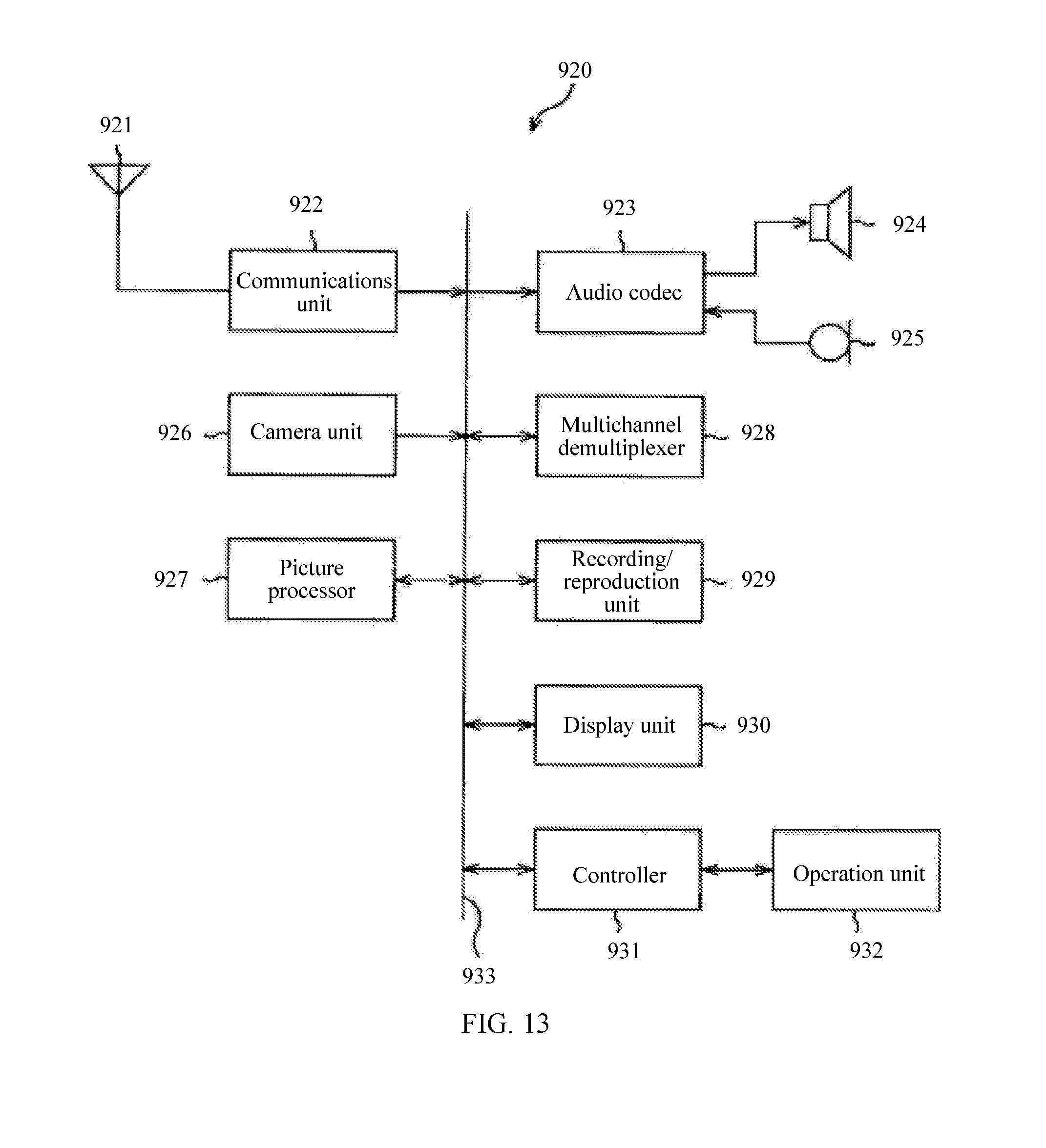


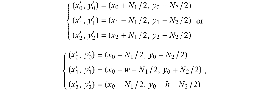

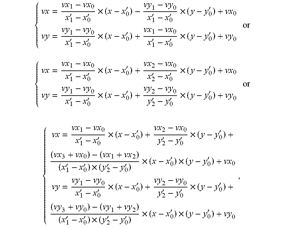
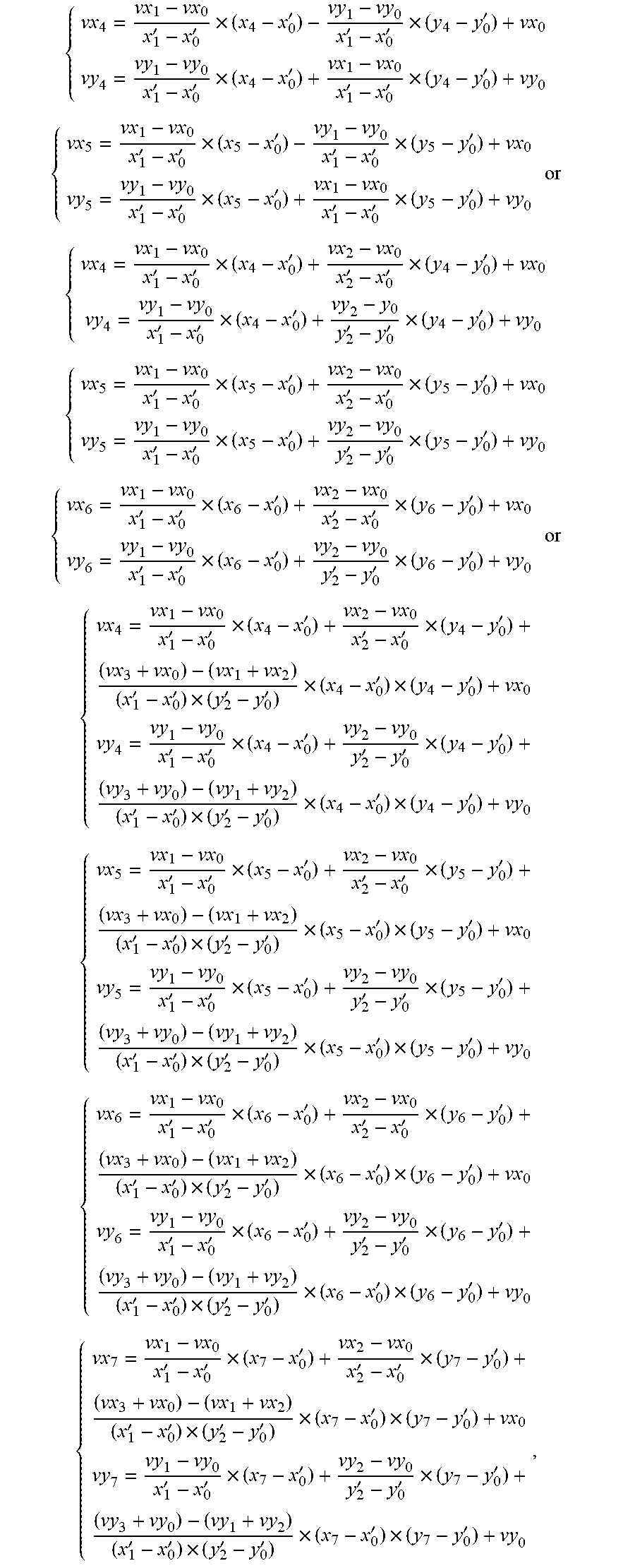


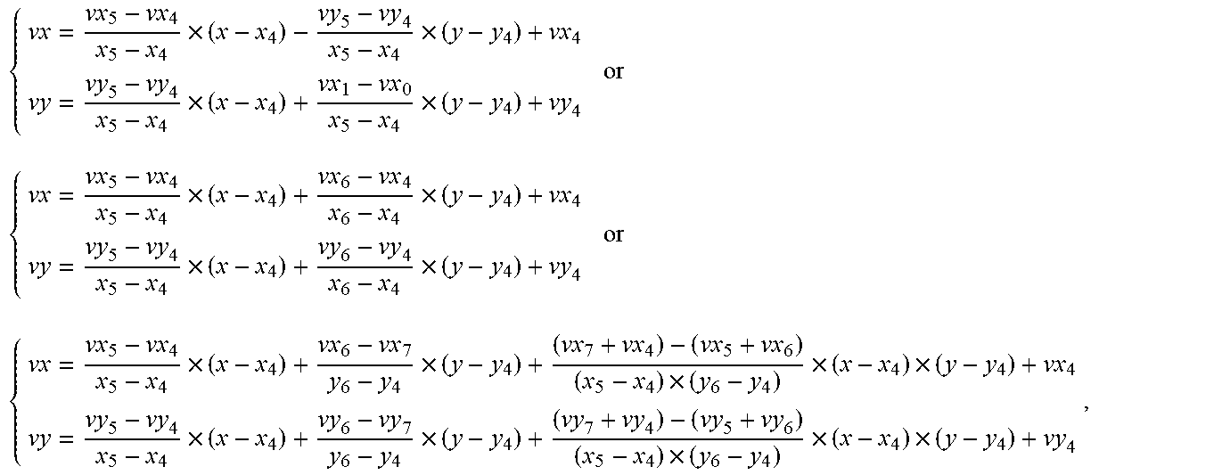


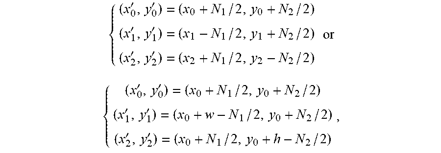
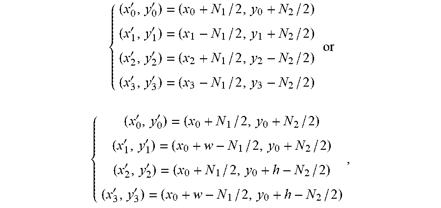

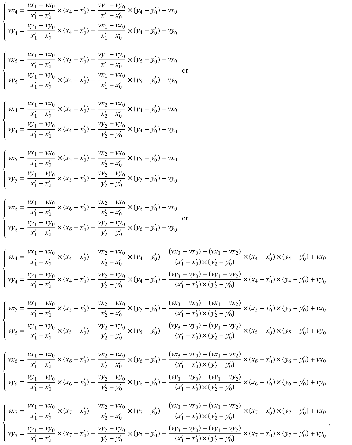
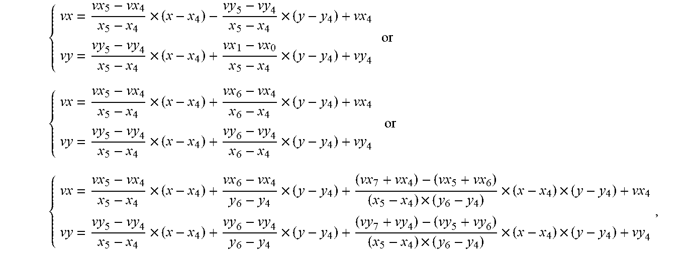

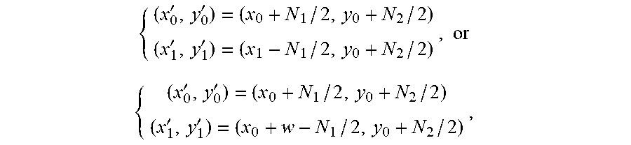


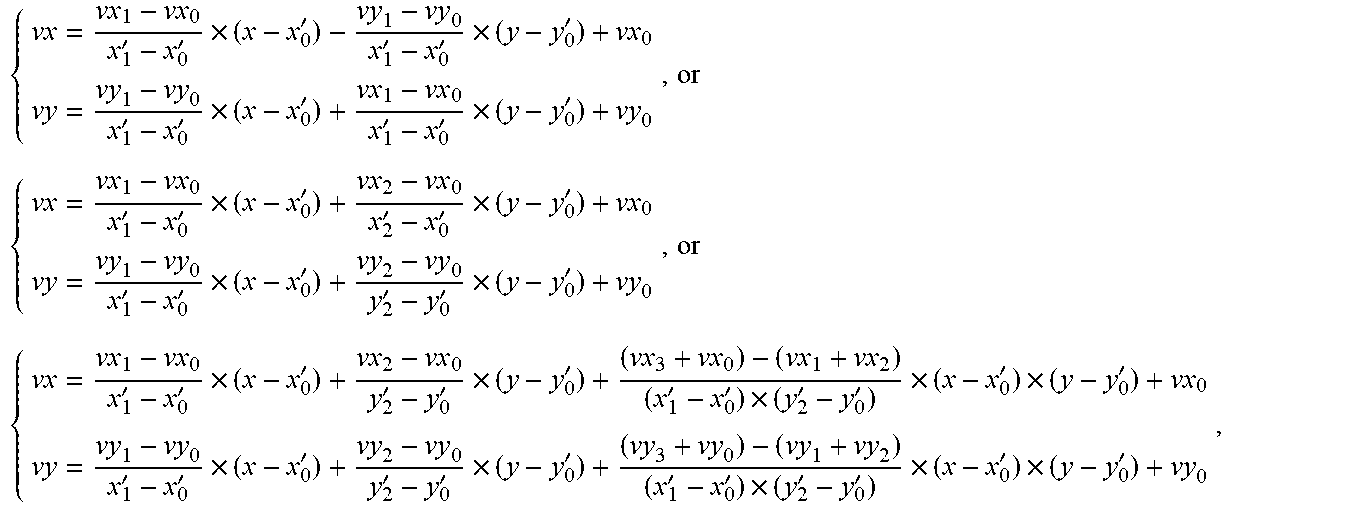


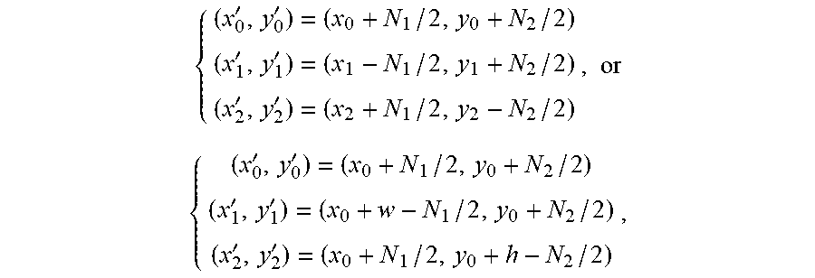


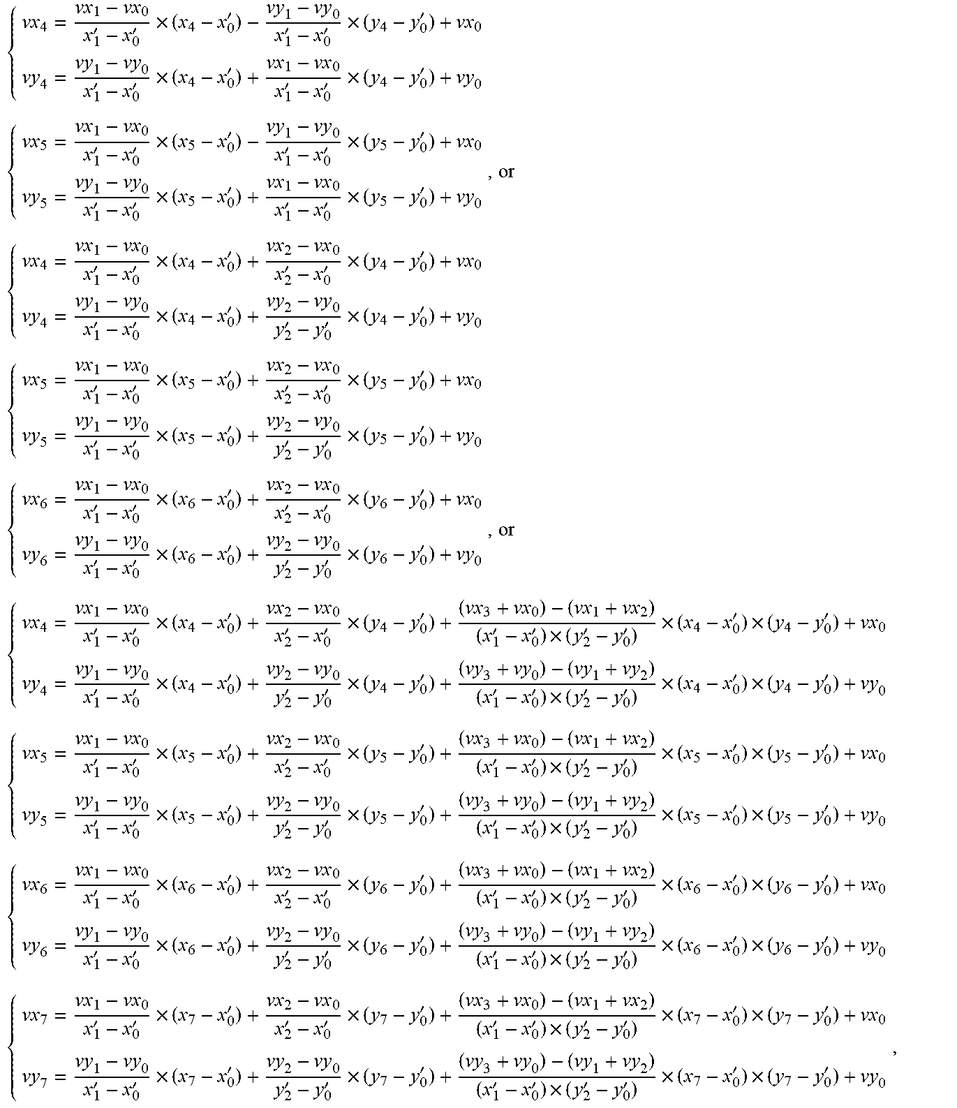

XML
uspto.report is an independent third-party trademark research tool that is not affiliated, endorsed, or sponsored by the United States Patent and Trademark Office (USPTO) or any other governmental organization. The information provided by uspto.report is based on publicly available data at the time of writing and is intended for informational purposes only.
While we strive to provide accurate and up-to-date information, we do not guarantee the accuracy, completeness, reliability, or suitability of the information displayed on this site. The use of this site is at your own risk. Any reliance you place on such information is therefore strictly at your own risk.
All official trademark data, including owner information, should be verified by visiting the official USPTO website at www.uspto.gov. This site is not intended to replace professional legal advice and should not be used as a substitute for consulting with a legal professional who is knowledgeable about trademark law.