Modular Patient Monitor
Kiani; Massi Joe E. ; et al.
U.S. patent application number 16/432240 was filed with the patent office on 2019-10-24 for modular patient monitor. The applicant listed for this patent is Masimo Corporation. Invention is credited to Ammar Al-Ali, Nicholas Evan Barker, Paul Ronald Jansen, Massi Joe E. Kiani, Michael O'Reilly, Anand Sampath.
| Application Number | 20190325722 16/432240 |
| Document ID | / |
| Family ID | 54203848 |
| Filed Date | 2019-10-24 |


View All Diagrams
| United States Patent Application | 20190325722 |
| Kind Code | A1 |
| Kiani; Massi Joe E. ; et al. | October 24, 2019 |
MODULAR PATIENT MONITOR
Abstract
A modular patient monitor provides a multipurpose, scalable solution for various patient monitoring applications. In an embodiment, a modular patient monitor utilizes multiple wavelength optical sensor and/or acoustic sensor technologies to provide blood constituent monitoring and acoustic respiration monitoring (ARM) at its core, including pulse oximetry parameters and additional blood parameter measurements such as carboxyhemoglobin (HbCO) and methemoglobin (HbMet). Expansion modules provide blood pressure BP, blood glucose, ECG, CO2, depth of sedation and cerebral oximetry to name a few. Aspects of the present disclosure also include a transport dock for providing enhanced portability and functionally to handheld monitors. In an embodiment, the transport dock provides one or more docking interfaces for placing monitoring components in communication with other monitoring components. In an embodiment, the transport dock attaches to the modular patient monitor.
| Inventors: | Kiani; Massi Joe E.; (Laguna Niguel, CA) ; Al-Ali; Ammar; (San Juan Capistrano, CA) ; O'Reilly; Michael; (San Jose, CA) ; Jansen; Paul Ronald; (San Clemente, CA) ; Barker; Nicholas Evan; (Laguna Beach, CA) ; Sampath; Anand; (Irvine, CA) | ||||||||||
| Applicant: |
|
||||||||||
|---|---|---|---|---|---|---|---|---|---|---|---|
| Family ID: | 54203848 | ||||||||||
| Appl. No.: | 16/432240 | ||||||||||
| Filed: | June 5, 2019 |
Related U.S. Patent Documents
| Application Number | Filing Date | Patent Number | ||
|---|---|---|---|---|
| 15814227 | Nov 15, 2017 | 10354504 | ||
| 16432240 | ||||
| 14733781 | Jun 8, 2015 | 9847002 | ||
| 15814227 | ||||
| 13039218 | Mar 2, 2011 | 9153112 | ||
| 14733781 | ||||
| 12973392 | Dec 20, 2010 | |||
| 13039218 | ||||
| 61407033 | Oct 27, 2010 | |||
| 61407011 | Oct 26, 2010 | |||
| 61405125 | Oct 20, 2010 | |||
| 61290436 | Dec 28, 2009 | |||
| 61288843 | Dec 21, 2009 | |||
| Current U.S. Class: | 1/1 |
| Current CPC Class: | A61B 2560/0443 20130101; A61B 5/7445 20130101; G06F 1/1654 20130101; G06F 1/165 20130101; G06F 1/1649 20130101; A61B 5/02438 20130101; A61B 5/08 20130101; A61B 5/6898 20130101; A61B 2560/0456 20130101; G06F 1/1632 20130101; A61B 5/02055 20130101; A61B 5/1455 20130101; G08B 13/22 20130101; A61B 5/7425 20130101 |
| International Class: | G08B 13/22 20060101 G08B013/22; A61B 5/00 20060101 A61B005/00; A61B 5/1455 20060101 A61B005/1455; A61B 5/024 20060101 A61B005/024; A61B 5/0205 20060101 A61B005/0205; A61B 5/08 20060101 A61B005/08 |
Claims
1. (canceled)
2. A docking station for a modular patient monitoring system, the docking station comprising: a plurality of docking ports for receiving monitoring components, the docking ports forming a mechanical and electrical connection with the monitoring components, the plurality of docking ports interchangeably usable by different monitoring components; and a housing comprising at least: a first docking port of the plurality of docking ports; and a second docking port of the plurality of docking ports, wherein the first and second docking ports are configured to simultaneously receive, within the housing, expansion modules sized at any of a plurality of sizes, the expansion modules forming mechanical and electrical connections with the docking station when docked.
3. The docking station of claim 2, wherein in a first configuration a first expansion module is attached to the first docking port and a second expansion module is attached to the second docking port, and wherein in a second configuration the first expansion module is attached to the second docking port and the second expansion module is attached to the first docking port.
4. The docking station of claim 3, wherein housing comprises a module dock configured to house the first and second docking ports.
5. The docking station of claim 4, wherein at least one of the first expansion module or the second expansion module provides monitoring of one or more additional parameters by a patient monitoring system attached to the docking station.
6. The docking station of claim 5, wherein the one or more additional parameters comprises at least one of: EEG, BP, ECG, temperature, or cardiac output.
7. A method for displaying measurements of physiological parameters on a display, the method comprising: receiving at least a first set of measurements of a first parameter from a first expansion module when the first expansion module is plugged into a docking station, wherein the docking station is in communication with a first display; receiving at least a second set of measurements of a second parameter from a second expansion module when the second expansion module is plugged into the docking station; and displaying measurements of at least the first and second sets of measurements on the first display, wherein the docking station is configured to allow simultaneous plugging of a plurality of expansion modules, that are sized at any of a plurality of sizes, into docking ports housed in a housing of the docking station.
8. The method according to claim 7, wherein the plurality of expansion modules are differently sized.
9. The method according to claim 8, wherein the first set or the second set of measurements comprises at least one of: a waveform or a numerical value.
10. The method according to claim 8, wherein the first set or the second set of measurements comprises at least one of: EEG, BP, ECG, temperature, or cardiac output.
11. A method for displaying measurements of physiological parameters on a display, the method comprising: receiving a first expansion module on a first docking port of a docking station, the first expansion module capable of measuring at least a first parameter, the docking station in communication with a first display; determining, through the first expansion module, one or more first measurements for the first parameter; displaying the first measurements on the first display; receiving a second expansion module on a second docking port of the docking station, the second expansion module capable of measuring at least a second parameter; determining, through the second expansion module, one or more second measurements for the second parameter; and displaying the second measurements on the first display, wherein the first and second docking ports are housed by a housing of the docking station, and wherein the first and second docking ports are configured to allow simultaneous plugging of expansion modules that are sized at any of a plurality of sizes.
12. The method according to claim 11, wherein at least one of the first measurements is different from the second measurements.
13. The method according to claim 12, wherein the plurality of expansion modules are differently sized.
14. The method according to claim 13, wherein the first or second measurements comprised at least one of: a waveform or a numerical value.
15. The method according to claim 13, wherein the first or the second measurements comprised at least one of: EEG, BP, ECG, temperature, or cardiac output.
Description
CROSS-REFERENCE TO RELATED APPLICATIONS
[0001] This application is a continuation of application Ser. No. 15/814,227, filed Nov. 15, 2017, entitled "Modular Patient Monitor," which is a continuation of application Ser. No. 14/733,781, filed Jun. 8, 2015, entitled "Modular Patient Monitor," which is a continuation of application Ser. No. 13/039,218, filed Mar. 2, 2011, entitled "Modular Patient Monitor," which is a continuation of application Ser. No. 12/973,392, filed Dec. 20, 2010, entitled "Modular Patient Monitor," which claims priority benefit under 35 U.S.C. .sctn. 119 (e) from U.S. Provisional Application No. 61/405,125, filed Oct. 20, 2010, entitled "Modular Patient Monitor," U.S. Provisional Application No. 61/288,843, filed Dec. 21, 2009, entitled "Acoustic Respiratory Monitor," U.S. Provisional Application No. 61/290,436, filed Dec. 28, 2009, entitled "Acoustic Respiratory Monitor," U.S. Provisional Application No. 61/407,011, filed Oct. 26, 2010, entitled "Integrated Physiological Monitoring System," and U.S. Provisional Application No. 61/407,033, filed Oct. 27, 2010, entitled "Medical Diagnostic and Therapy System," which are incorporated herein by reference in their entirety.
FIELD OF THE DISCLOSURE
[0002] The disclosure relates to the field of physiological monitors, and more specifically to a modular monitoring system.
BACKGROUND OF THE DISCLOSURE
[0003] Patient monitoring of various physiological parameters of a patient is important to a wide range of medical applications. Oximetry is one of the techniques that has developed to accomplish the monitoring of some of these physiological characteristics. It was developed to study and to measure, among other things, the oxygen status of blood. Pulse oximetry--a noninvasive, widely accepted form of oximetry--relies on a sensor attached externally to a patient to output signals indicative of various physiological parameters, such as a patient's constituents and/or analytes, including for example a percent value for arterial oxygen saturation, carbon monoxide saturation, methemoglobin saturation, fractional saturations, total hematocrit, bilirubins, perfusion quality, or the like. A pulse oximetry system generally includes a patient monitor, a communications medium such as a cable, and/or a physiological sensor having light emitters and a detector, such as one or more LEDs and a photodetector. The sensor is attached to a tissue site, such as a finger, toe, ear lobe, nose, hand, foot, or other site having pulsatile blood flow which can be penetrated by light from the emitters. The detector is responsive to the emitted light after attenuation by pulsatile blood flowing in the tissue site. The detector outputs a detector signal to the monitor over the communication medium, which processes the signal to provide a numerical readout of physiological parameters such as oxygen saturation (SpO2) and/or pulse rate.
[0004] High fidelity pulse oximeters capable of reading through motion induced noise are disclosed in U.S. Pat. Nos. 7,096,054, 6,813,511, 6,792,300, 6,770,028, 6,658,276, 6,157,850, 6,002,952 5,769,785, and 5,758,644, which are assigned to Masimo Corporation of Irvine, Calif. ("Masimo Corp.") and are incorporated by reference herein. Advanced physiological monitoring systems can incorporate pulse oximetry in addition to advanced features for the calculation and display of other blood parameters, such as carboxyhemoglobin (HbCO), methemoglobin (HbMet), total hemoglobin (Hbt), total Hematocrit (Hct), oxygen concentrations, glucose concentrations, blood pressure, electrocardiogram data, temperature, and/or respiratory rate as a few examples. Typically, the physiological monitoring system provides a numerical readout of and/or waveform of the measured parameter.
[0005] Advanced physiological monitors and multiple wavelength optical sensors capable of measuring parameters in addition to SpO2, such as HbCO, HbMet and/or Hbt are described in at least U.S. patent application Ser. No. 11/367,013, filed Mar. 1, 2006, entitled Multiple Wavelength Sensor Emitters and U.S. patent application Ser. No. 11/366,208, filed Mar. 1, 2006, entitled Noninvasive Multi-Parameter Patient Monitor, assigned to Masimo Laboratories, Inc. and incorporated by reference herein. Pulse oximetry monitors and sensors are described in U.S. Pat. No. 5,782,757 entitled Low Noise Optical Probes and U.S. Pat. No. 5,632,272 entitled Signal Processing Apparatus, both incorporated by reference herein. Further, noninvasive blood parameter monitors and optical sensors including Rainbow.TM. adhesive and reusable sensors and RAD-57.TM. and Radical-7.TM. monitors capable of measuring SpO2, pulse rate, perfusion index (PI), signal quality (SiQ), pulse variability index (PVI), HbCO and/or HbMet, among other parameters, are also commercially available from Masimo Corp. Acoustic respiration sensors and monitors are described in U.S. Pat. No. 6,661,161 entitled Piezoelectric Biological Sound Monitor with Printed Circuit Board and U.S. patent application Ser. No. 11/547,570 filed Jun. 19, 2007 entitled Non-Invasive Monitoring of Respiration Rate, Heart Rate and Apnea, both incorporated by reference herein.
SUMMARY OF THE DISCLOSURE
[0006] A modular patient monitor provides a multipurpose, scalable solution for various patient monitoring applications. In an embodiment, a modular patient monitor utilizes multiple wavelength optical sensor and/or acoustic sensor technologies to provide blood constituent monitoring and acoustic respiration monitoring (ARM) at its core, including pulse oximetry parameters and additional blood parameter measurements such as carboxyhemoglobin (HbCO) and methemoglobin (HbMet).
[0007] Expansion modules provide measurement and/or processing of measurements for blood pressure BP, blood glucose, electrocardiography (ECG), CO2, depth of sedation and cerebral oximetry to name a few. The modular patient monitor is advantageously scalable in features and cost from a base unit to a high-end unit with the ability to measure multiple parameters from a variety of sensors. In an embodiment, the modular patient monitor incorporates advanced communication features that allow interfacing with other patient monitors and medical devices.
[0008] Aspects of the present disclosure also include a transport dock for providing enhanced portability and functionally to handheld monitors. In an embodiment, the transport dock provides one or more docking interfaces for placing monitoring components in communication with other monitoring components. In an embodiment, the transport dock attaches to the modular patient monitor.
[0009] The modular patient monitor is adapted for use in hospital, sub-acute and general floor standalone, multi-parameter measurement applications by physicians, respiratory therapists, registered nurses and other trained clinical caregivers. It can be used in the hospital to interface with central monitoring and remote alarm systems. It also can be used to obtain routine vital signs and advanced diagnostic clinical information and as an in-house transport system with flexibility and portability for patient ambulation. Further uses for the modular patient monitor can include clinical research and other data collection.
BRIEF DESCRIPTION OF THE DRAWINGS
[0010] Throughout the drawings, reference numbers may be re-used to indicate correspondence between referenced elements. The drawings are provided to illustrate embodiments of the disclosure described herein and not to limit the scope thereof.
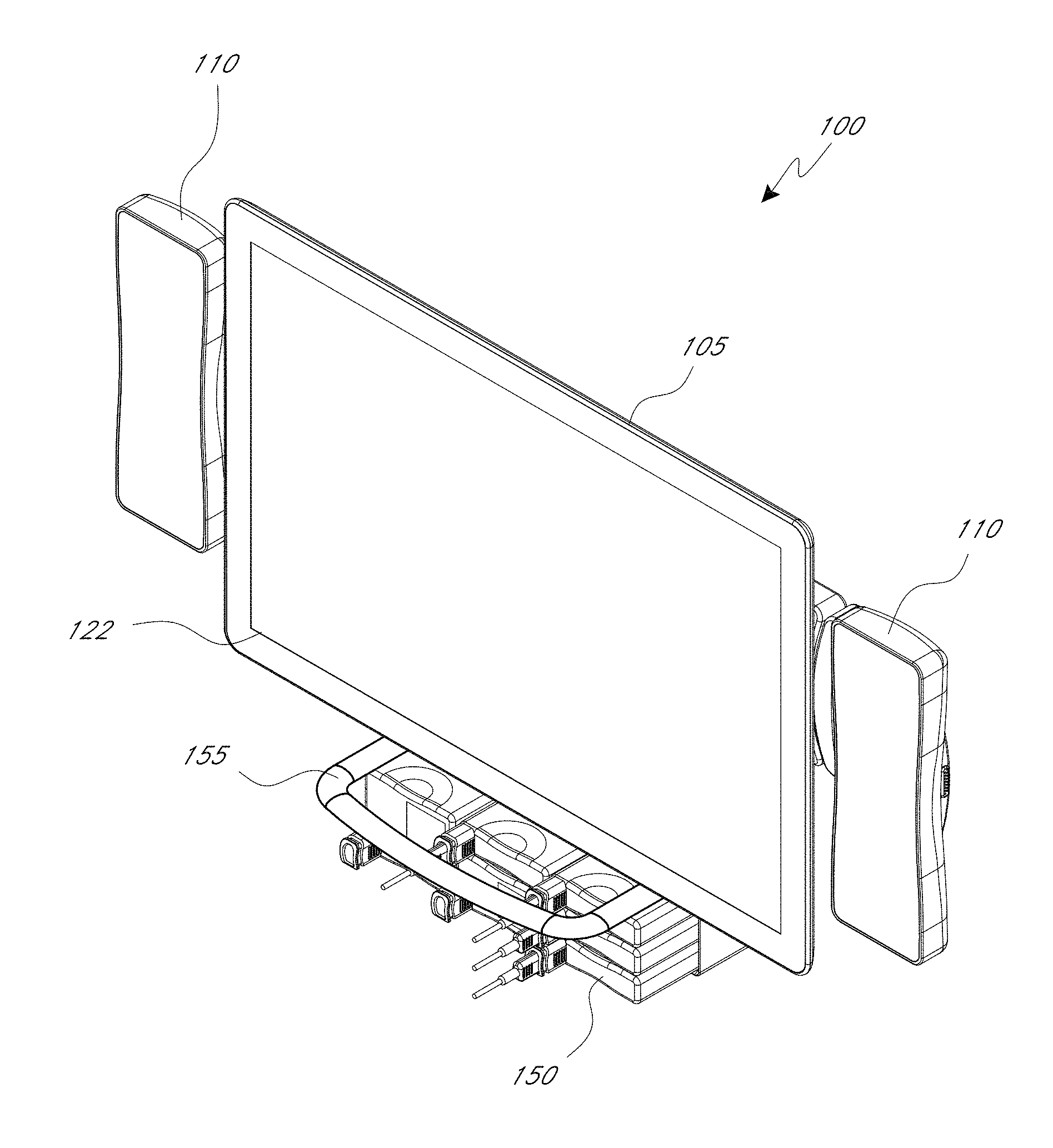
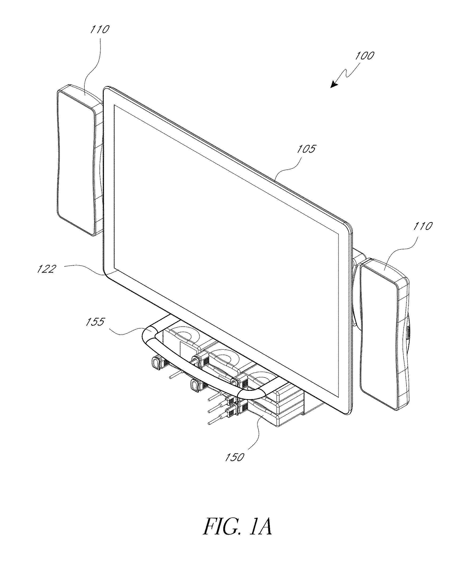
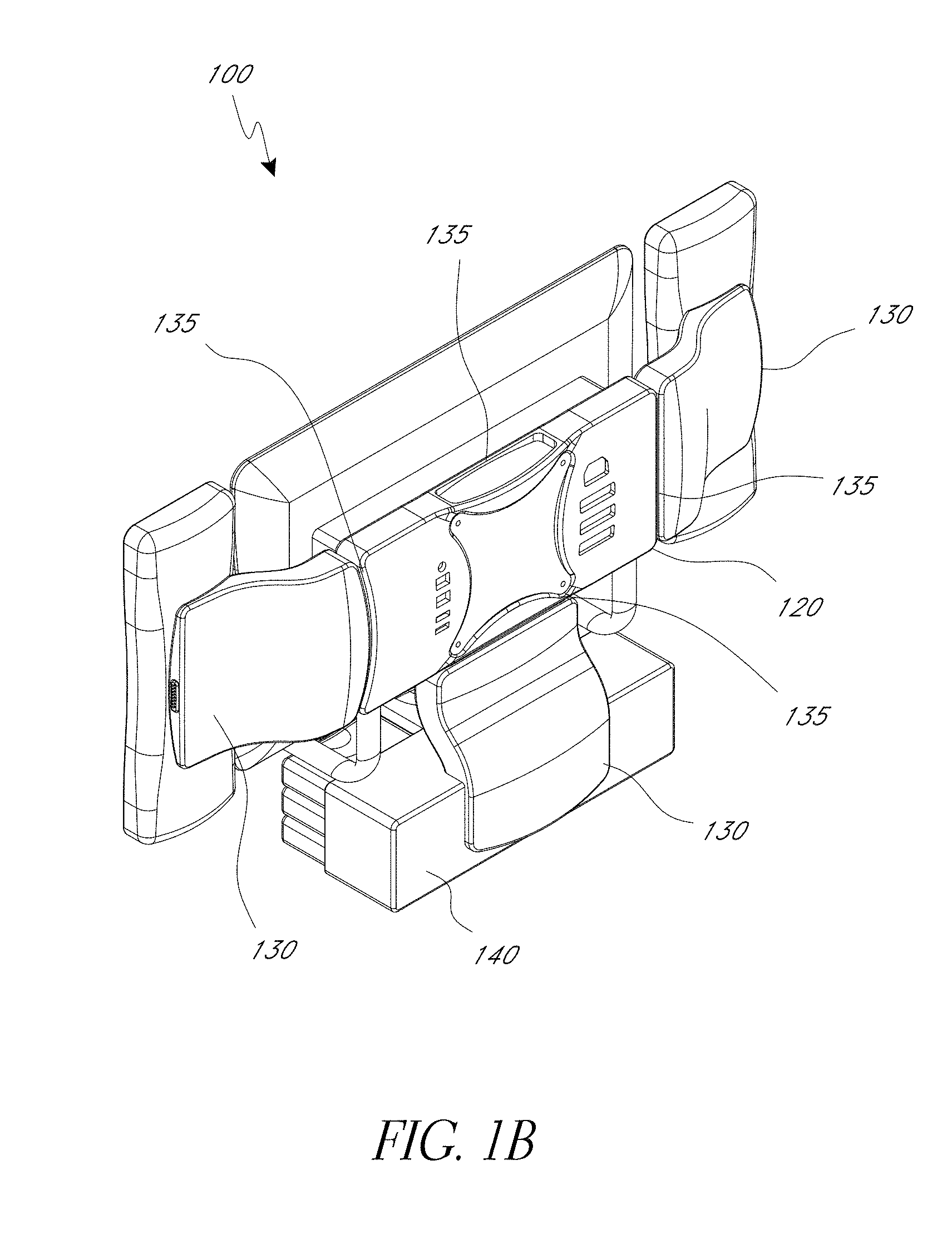
[0011] FIGS. 1A-1C illustrate front and rear perspective views and an exploded view of an embodiment of a modular patient monitor 100 having a modular configuration;
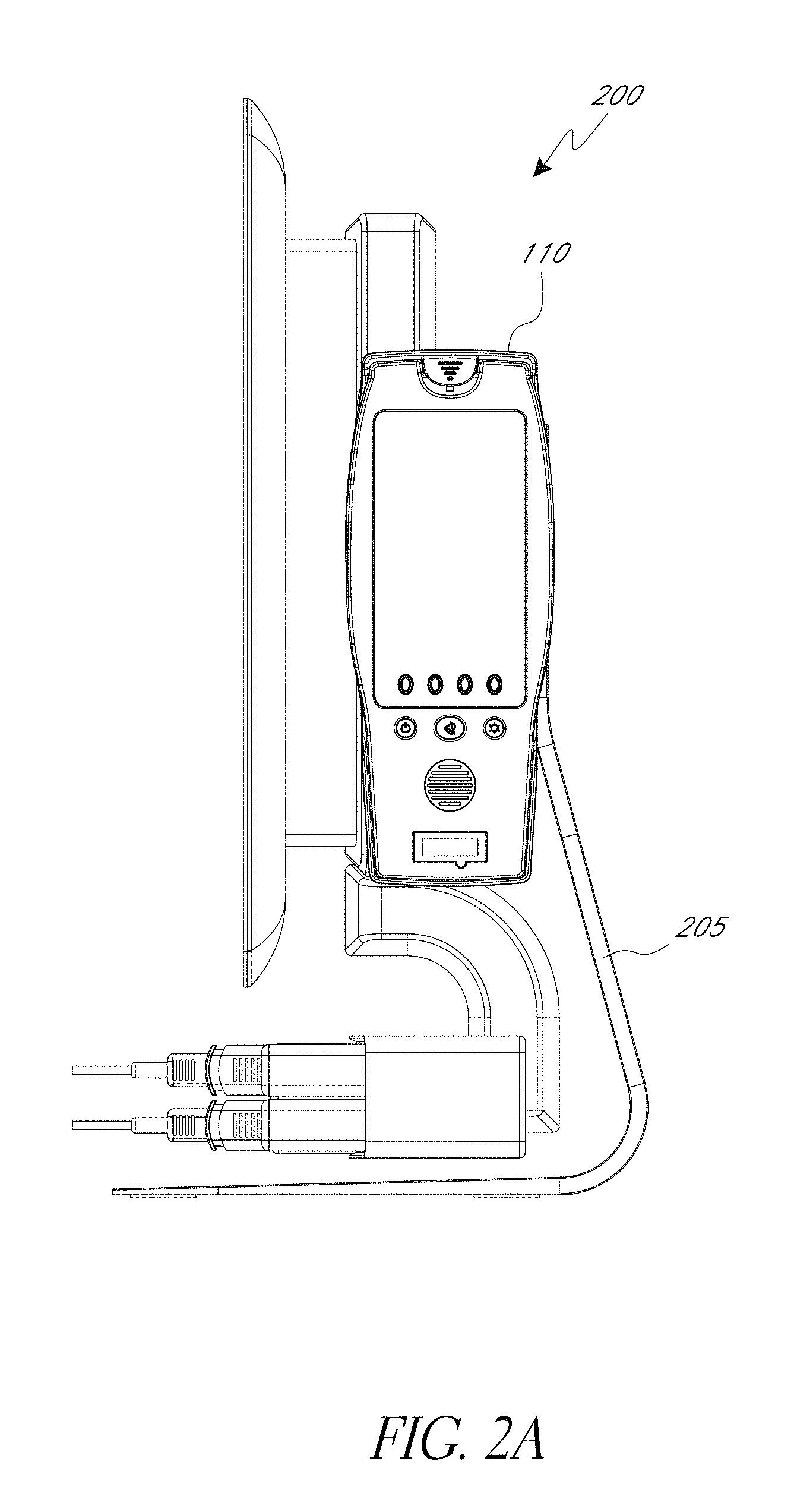
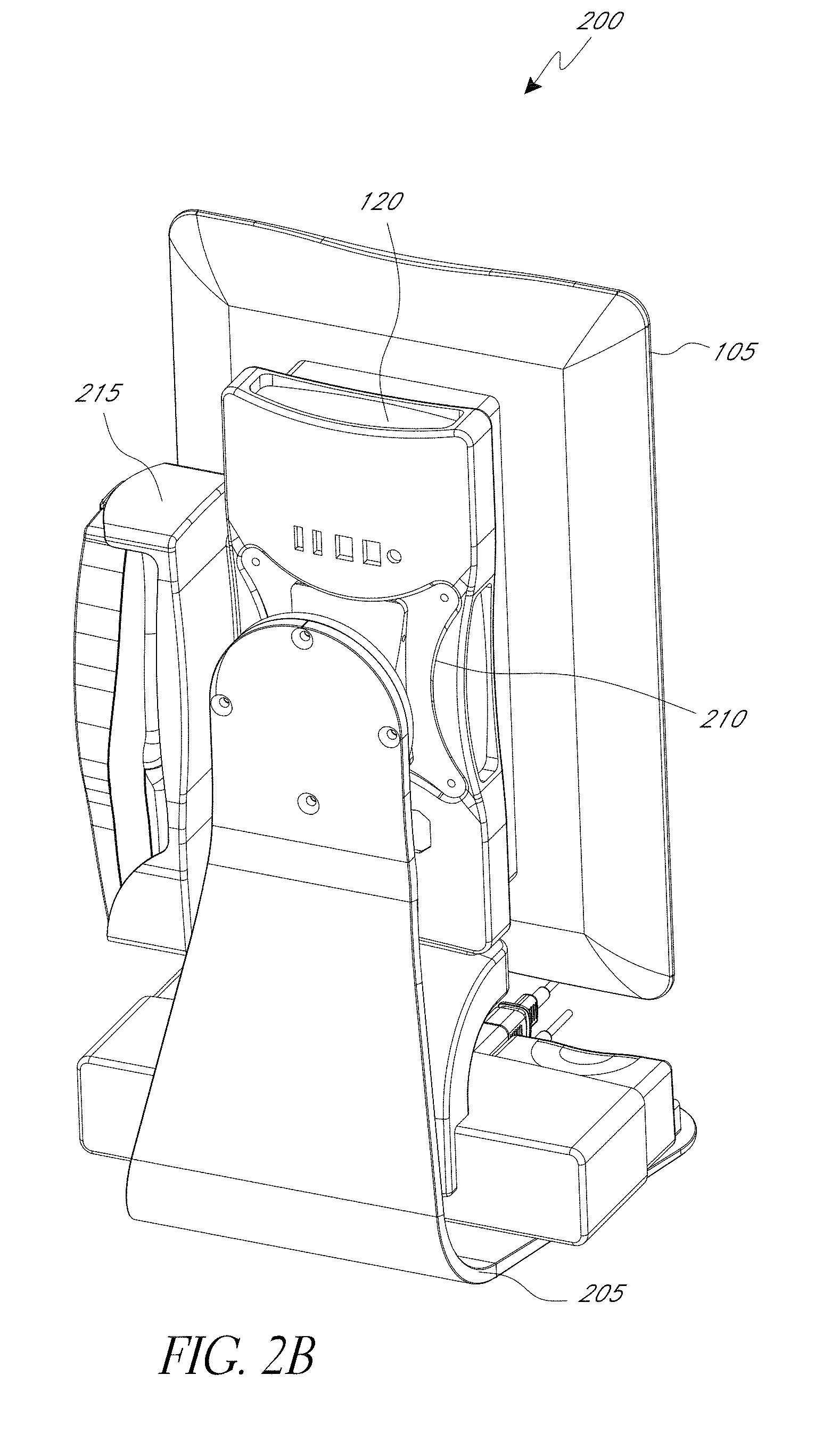
[0012] FIGS. 2A-2B illustrate side and rear views of a modular patient monitor embodiment 200 having an attached stand;
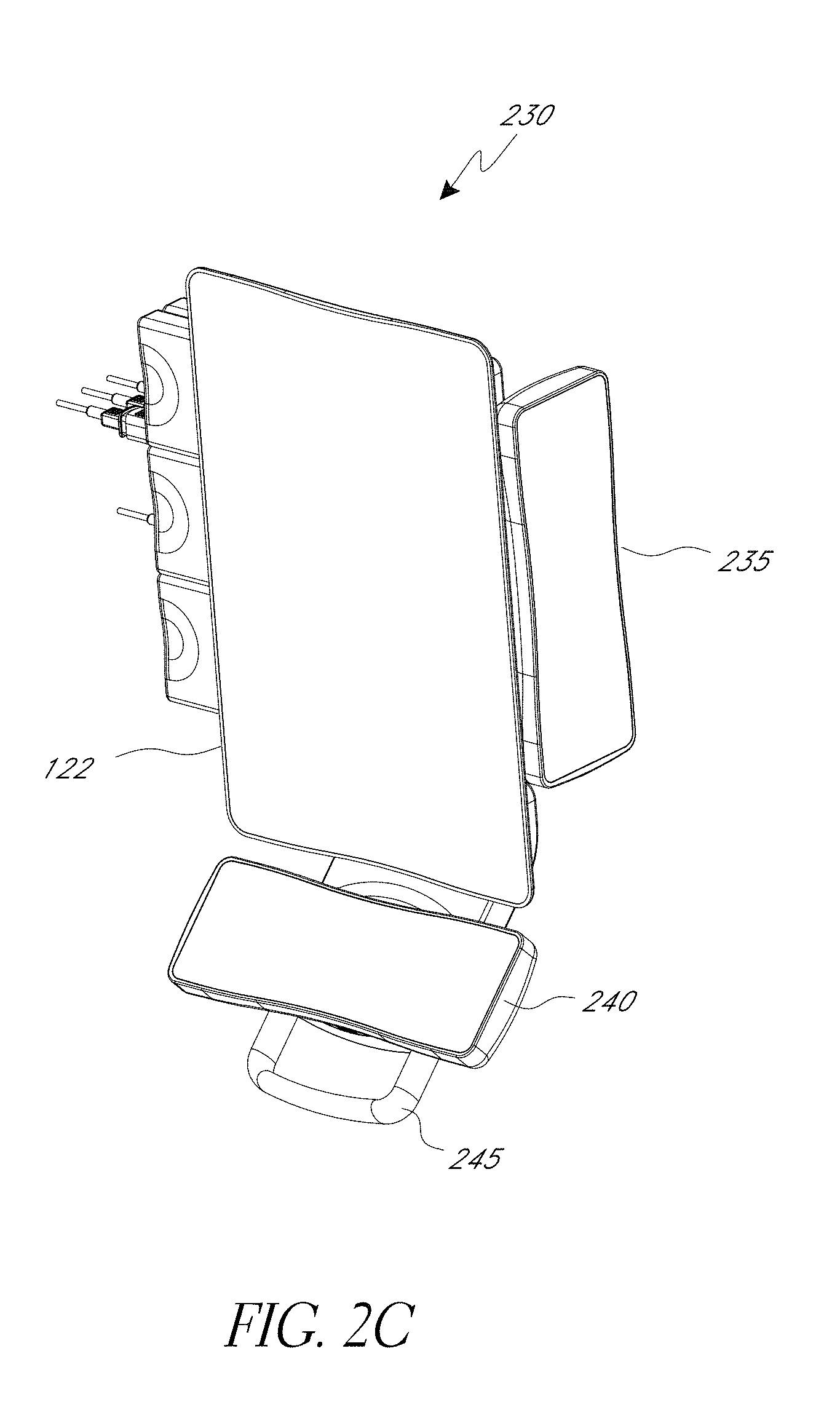
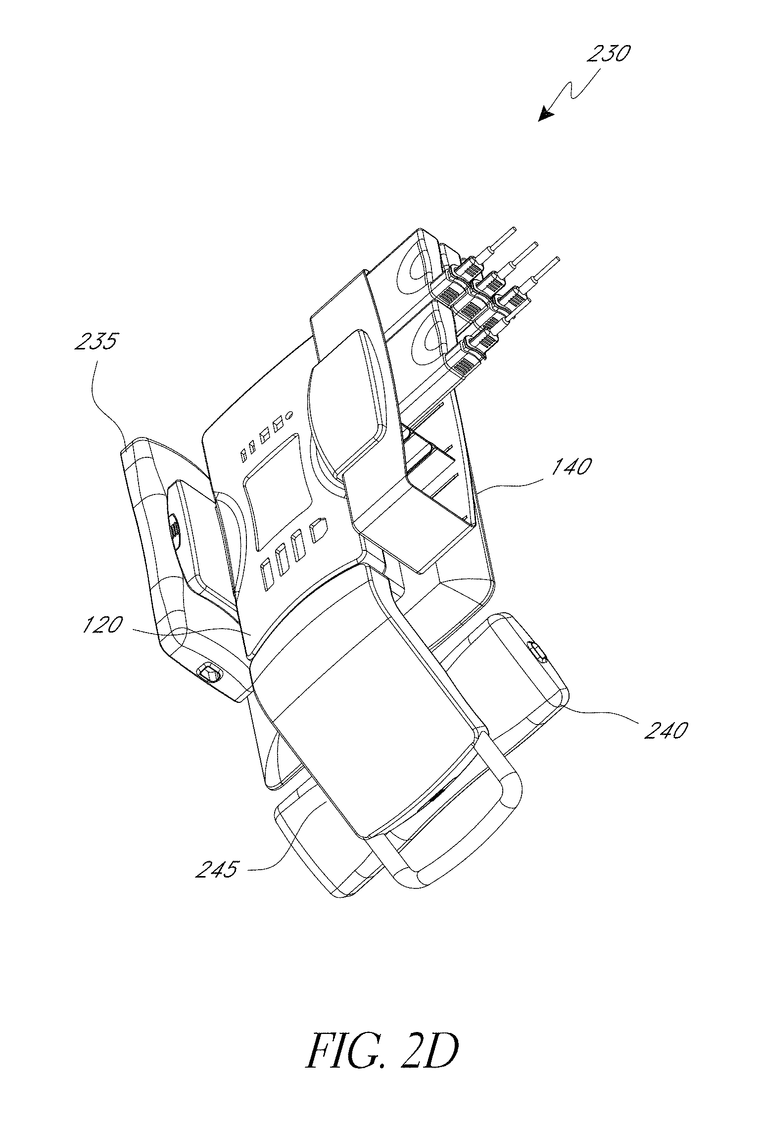
[0013] FIGS. 2C-2D illustrate front and rear perspective views of an embodiment of the modular patient monitor having two handheld monitors attached to the docking station with each handheld monitor in a different orientation;
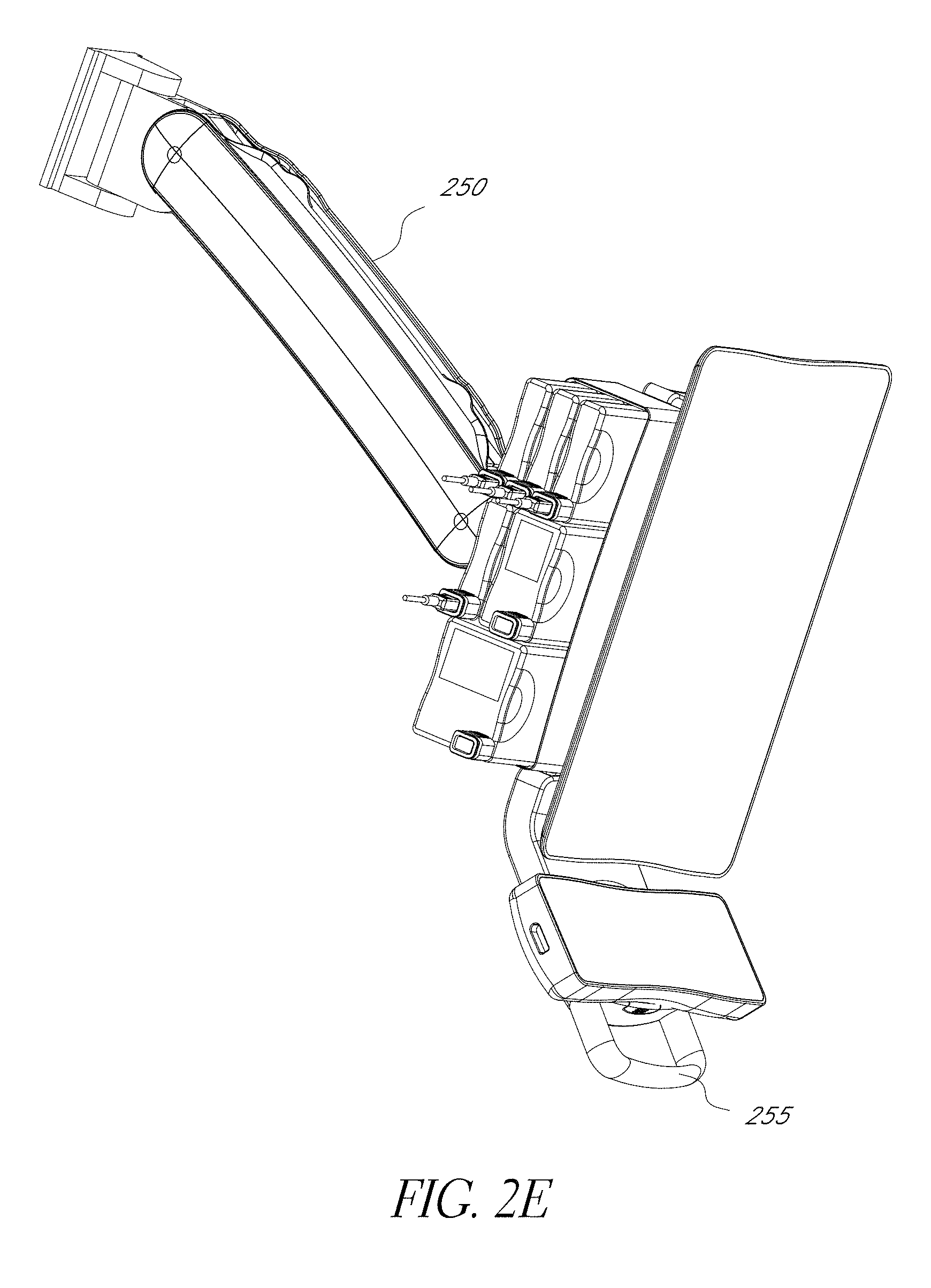
[0014] FIGS. 2E-2G illustrate front and rear perspective views and an exploded view of the modular patient monitor embodiment of FIGS. 2C and 2D attached to a mounting arm;
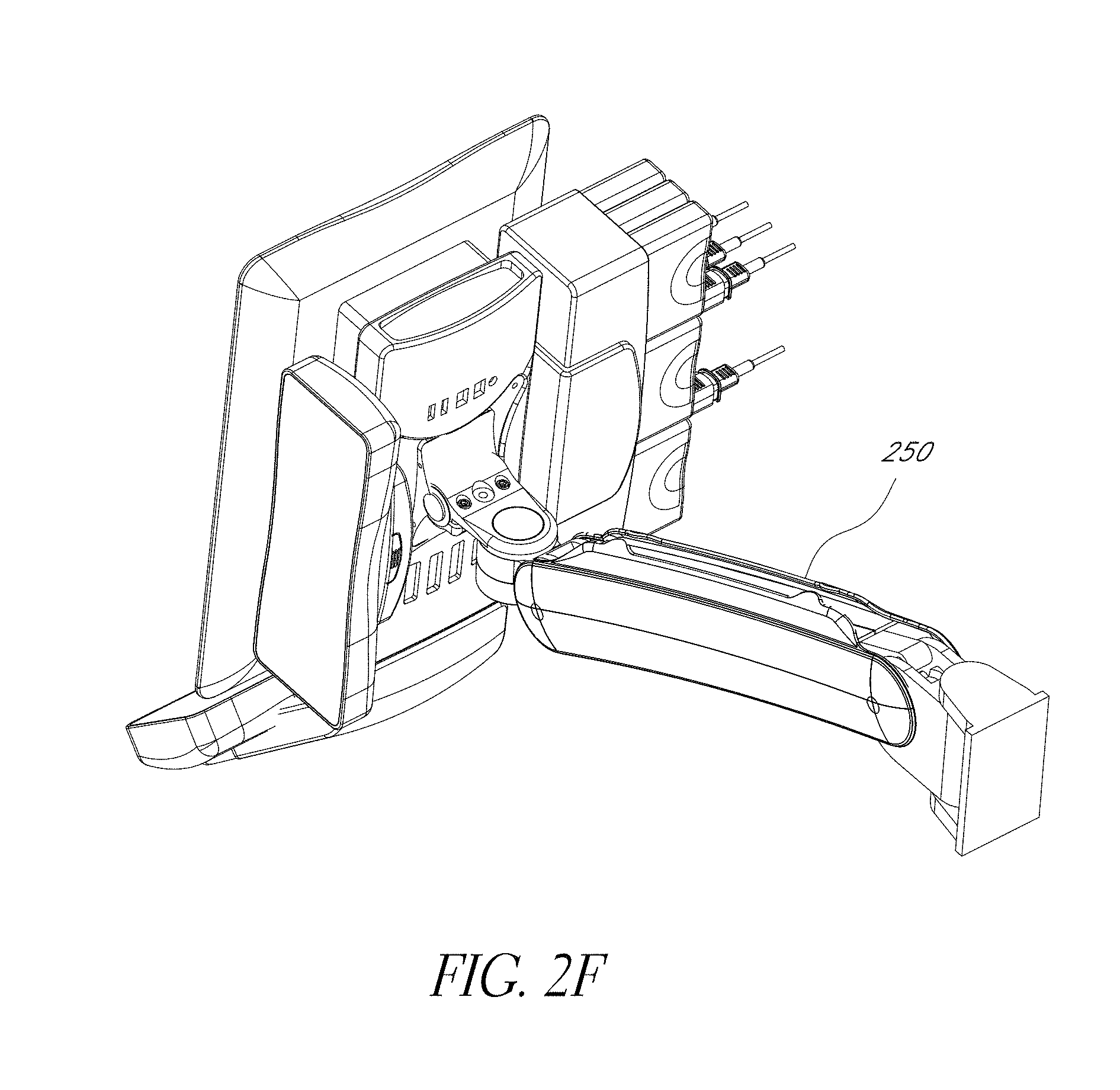
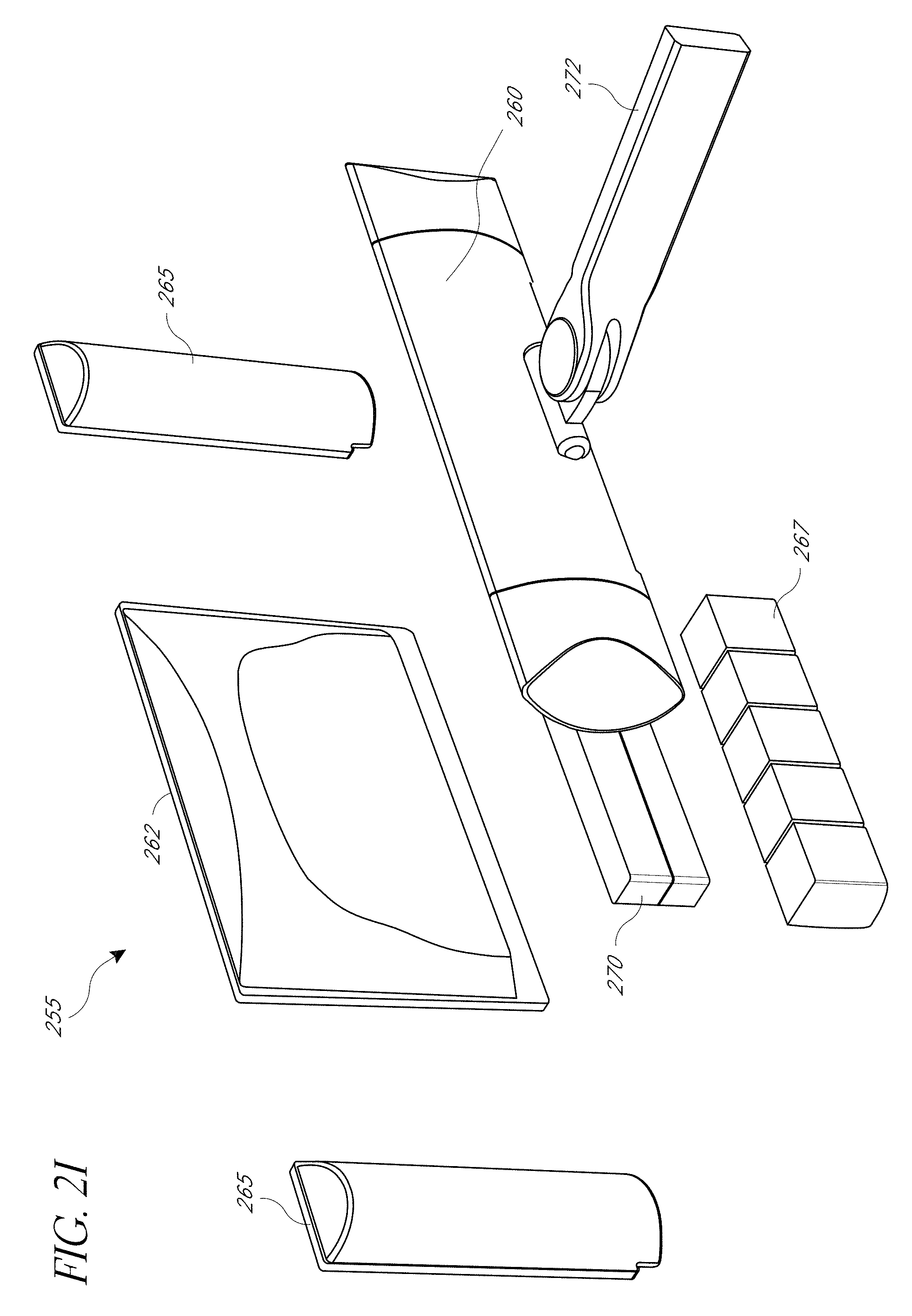
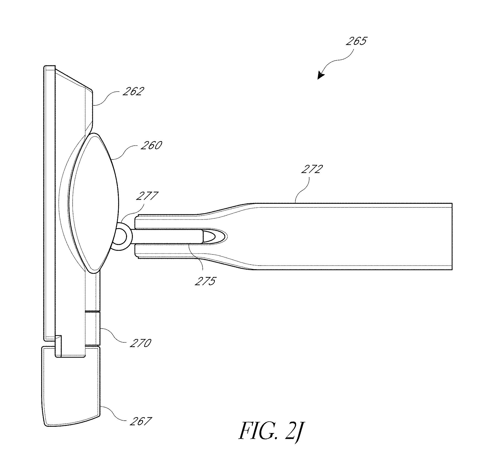
[0015] FIGS. 2H-2J illustrate rear perspective, exploded, and side views, respectively, of another embodiment of the modular patient monitor;
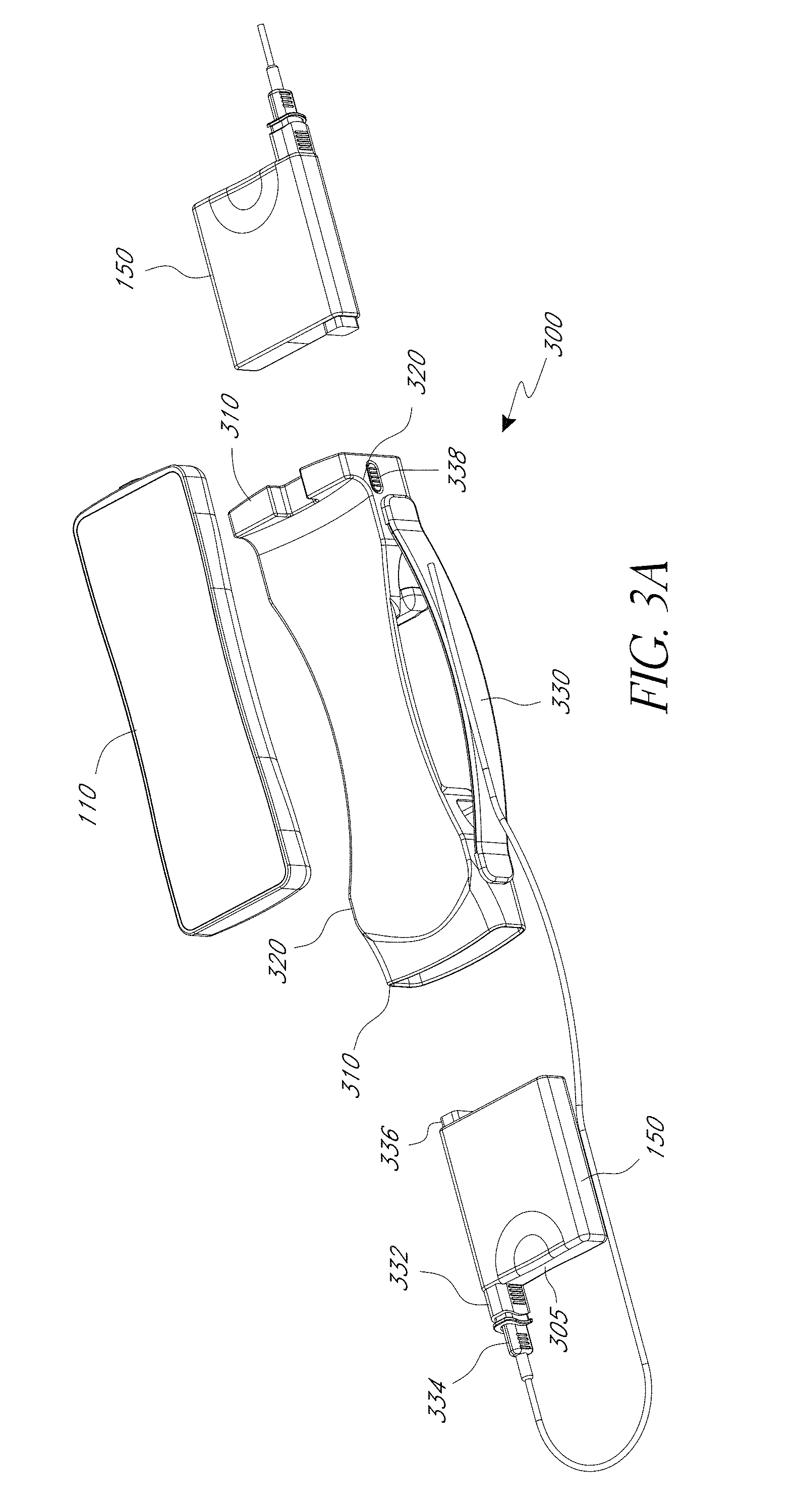
[0016] FIGS. 3A-3B illustrate perspective views of an embodiment of a transport dock;
[0017] FIG. 3C illustrates a perspective view of another embodiment of a transport dock;
[0018] FIG. 3D illustrates a perspective views of another embodiment of a transport dock with a multi-size docking port;
[0019] FIG. 3E illustrates a perspective views of another embodiment of a transport dock with an attached docking arm;
[0020] FIGS. 4A-4D illustrate embodiments of a monitoring tablet;
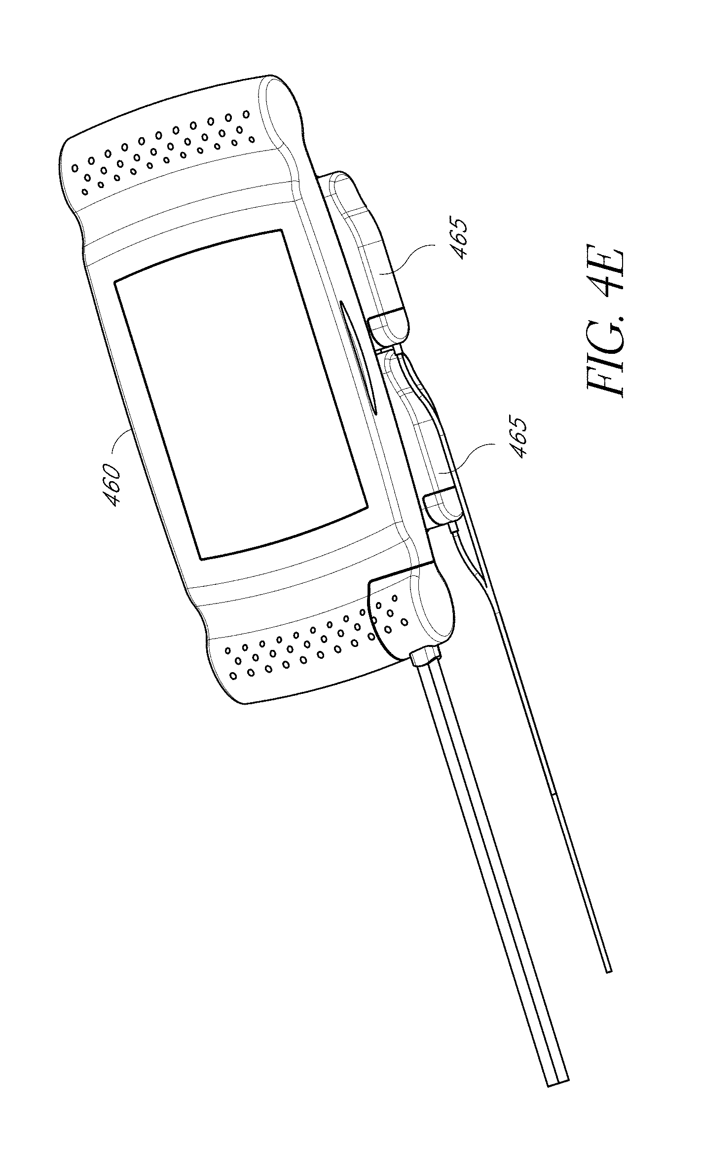
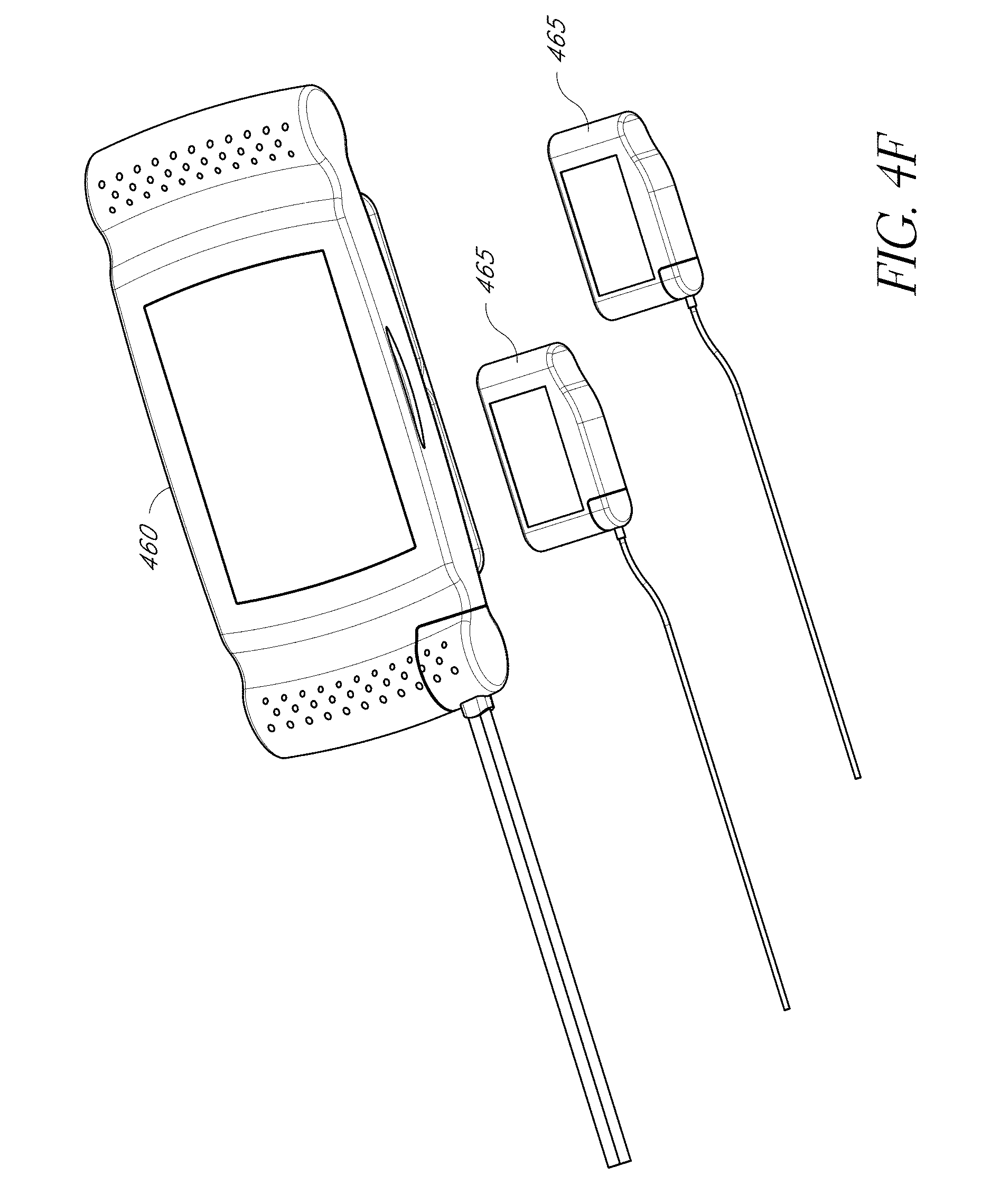
[0021] FIGS. 4E-4F illustrate perspective and exploded views, respectively, of a monitoring tablet embodiment having multiple expansion slots;
[0022] FIGS. 5A1-5E illustrate docking station embodiments capable of receiving a transport dock, monitoring tablet, and/or handheld monitor;
[0023] FIG. 6 illustrates a front view of the embodiment of the modular patient monitor of FIGS. 2H-2J, displaying measurements for parameters across multiple displays;
[0024] FIG. 7 illustrates a general block diagram of a physiological monitoring family;
[0025] FIGS. 8A-8E are top, front, bottom, side and perspective views, respectively, of a handheld monitor embodiment;
[0026] FIGS. 9A-9D are top, front, side and perspective views, respectively, of a tablet monitor embodiment;
[0027] FIGS. 10A-10E are top, front, side, perspective and exploded views, respectively, of a 3.times.3 rack embodiment with mounted display modules;
[0028] FIGS. 11A-11E are top perspective, front, side, and exploded views, respectively, of a 1.times.3 rack embodiment with mounted monitor, control and/or display modules;
[0029] FIGS. 12A-12D are top, front, side and perspective views, respectively, of a large display and display bracket;
[0030] FIGS. 13A-13B are perspective and exploded views of another embodiment of a modular patient monitor;
[0031] FIG. 13C illustrates a perspective view of an embodiment of a 3.times.1 docking station;
[0032] FIGS. 14A-14B illustrates an embodiment of the monitor module of FIG. 13A-13B used in combination with a single port dock; and
[0033] FIG. 15 illustrates an embodiment of a single port dock.
DETAILED DESCRIPTION
[0034] FIGS. 1A and 1B illustrate front and rear views of an embodiment of a modular patient monitor 100 having a modular configuration, one or more handheld 110 units and a configurable docking station 120. FIG. 3A illustrates an exploded view of the patient monitor 100 embodiment. The docking station 120 can include a primary patient monitor 105 integrated with the docking station or that attaches mechanically and/or electrically to the docking station via a docking port. In one embodiment, the docking station does not include a primary patient monitor 105.
[0035] One or more handheld monitoring devices can attach mechanically and/or electrically with the docking station 120 via one or more docking ports 135. In one embodiment, mechanical attachment is accomplished through a releasable mechanism, such as locking tabs, pressure fit, hooks, clips, a spring lock or the like. In one embodiment, the docking ports 135 provide a data interface, for example, through its electrical connection. In one embodiment, the electrical connection can provide power to the monitoring device. The handheld 110 docks into a docking arm 130 of the docking station 120, providing the modular patient monitor 100 with additional functionality. In particular, the handheld 110 can provide a specific set of clinically relevant parameters. For example, the handheld 110 supports various parameters that are configured to specific hospital environments and/or patient populations including general floor, OR, ICU, ER, NICU, to name a few. In one embodiment, docking the handheld 110 into the docking station 120 allows access to additional available parameters and provides increased connectivity, functionality and/or a larger display 122. A multi-monitor patient monitor is described in U.S. patent application Ser. No. 12/641,087 titled Modular Patient Monitor, filed Dec. 17, 2009, incorporated by reference herein in its entirety.
[0036] In one embodiment, the docking station 120 includes a plurality of docking ports 135 of identical or standard size, interface, and/or configuration. Each docking port can accept different monitoring components with a corresponding standard connector. In one embodiment, different types of monitoring components, such as a handheld monitor 110 or module dock 140, can be interchangeably connected to different docking ports 135. For example, in a first configuration, a first docking port receives the handheld monitor 110 and a second docking port receives the module dock 140, while in a second configuration, the first docking port receives the module dock 140 and the second docking port receives the handheld monitor 110. By providing interchangeable docking ports, users of the modular patient monitor 100 have greater ability to customize the monitor 100 according to their needs. For example, if more displays are needed then additional docking ports can receive displays or handheld monitors but if more parameters are desired or need to be monitored, then additional docking ports can receive module docks and/or expansion modules. In one embodiment, docking ports 135 incorporate USB, IEEE 1394, serial, and/or parallel connector technology.
[0037] A docking arm 130 can be detachably connected or integrated with the docking station and/or monitoring component, such a handheld monitor 110 or module dock. In one embodiment, a docking arm 130 attaches mechanically and/or electrically to a handheld monitor 110 on one end and attaches mechanically and/or electrically to a docking port 135 of the docking station 120 on another end. In one embodiment, the docking arm 130 is configured to orient the display of the handheld monitor 110 in a particular orientation. For example, the docking arm 130 can orient the handheld monitor 110 in the same direction as a main display 122 or can angle the handheld monitor 110 in order to display parameters in other directions. In some embodiments, the handheld monitor 110 may be oriented at an angle (e.g. 30, 60, 90 degrees, or the like) from the main display 122, vertically, horizontally, or in a combination of directions. The handheld monitor 100 can be oriented at an angle towards the front or back of the main display 122. In one embodiment, the docking arm 130 is movable and configurable to a variety of orientations. In one embodiment, the docking arm 130 comprises a swivel joint, ball joint, rotating joint, or other movable connector for allowing the docking arm 130 to rotate, twist, or otherwise move an attached monitor 110. For example, the movable connector can rotate on one or more axis, allowing the attached monitor 110 to be oriented in multiple directions. In some embodiments, monitoring components can be directly attached to the docking station without using a docking arm 130.
[0038] In the illustrated embodiment of FIGS. 1A and 1B, the docking station 120 is rectangular shaped, having a display on one side, a mounting connector on the opposite side, and four docking ports 135 on the top, bottom, and side edges of the docking station 120. In other embodiments, additional or fewer docking ports 135 can be included on the docking station 120. In some embodiments, the docking ports 135 can provide electrical and/or mechanical connections to handheld monitors 110, module docks 140 with one or more module ports, expansion modules 150 and/or other monitoring components. The monitoring components can attach to a docking port 135 via a docking arm 130 or directly to the port 135. For example, the docking station 120 can include an expansion module 150 or a module dock 140 that accepts plug-in expansion modules 150 for monitoring additional parameters or adding additional monitoring technologies. For example, an expansion module 150 can enable monitoring of electroencephalography (EEG), blood pressure (BP), ECG, temperature, and/or cardiac output. In one embodiment, measurements taken by the monitor are processed by the expansion module. In some embodiments, the expansion module provides attachments for sensors and receives measurements directly from the sensors.
[0039] In one embodiment, the module dock 140 functions as a stand for the modular patient monitor 100. In another embodiment, the stand is independent of the module dock 140. In one embodiment, the modular patient monitor 100 provides standalone multi-parameter applications, and the handheld 110 is detachable to provide portability for patient ambulation and in-house transport.
[0040] In one embodiment, the module dock 140 provides an interface for expansion modules 150, provides charging for expansion modules 150, and/or interconnects multiple expansion modules by providing a communications medium for data communications between expansion modules and/or other components. For example, the module dock 140 can provide a data interface with a patient monitor or docking station 120, allowing data to be transmitted to and from the expansion modules. In one embodiment, the module dock 140 operates independently of the docking station 120. In one embodiment, the module dock includes a wireless transmitter and/or receiver for communicating wirelessly with the patient monitor or docking station 120.
[0041] The handheld monitor 110 and/or primary patient monitor 105 can provide pulse oximetry parameters including oxygen saturation (SpO.sub.2), pulse rate (PR), perfusion index (PI), signal quality (SiQ) and a pulse waveform (pleth), among others. In an embodiment, the handheld 110 and/or primary patient monitor 105 also provides measurements of other blood constituent parameters that can be derived from a multiple wavelength optical sensor, such as carboxyhemoglobin (HbCO) and methemoglobin (HbMet). In one embodiment, the handheld 110 and/or primary patient monitor 105 has a color display, user interface buttons, an optical sensor port and a speaker. The handheld 110 and/or primary patient monitor 105 can include external I/O such as a bar code reader and bedside printer connectivity. The handheld 110 and/or primary patient monitor 105 can display additional parameters, such as Sp.sub.vO.sub.2, blood glucose, lactate to name a few, derived from other noninvasive sensors such as acoustic, fetal oximetry, blood pressure and ECG sensors to name a few. In an embodiment, the handheld unit 110 and/or primary patient monitor 105 has an active matrix (TFT) color display, an optional wireless module, an optional interactive touch-screen with on-screen keyboard and a high quality audio system. In another embodiment, the handheld 110 is a Radical.RTM. or Radical-7.TM. available from Masimo Corporation, Irvine Calif., which provides Masimo SET.RTM. and Masimo Rainbow.TM. parameters. A color LCD screen handheld user interface is described in U.S. Provisional Patent Application No. 60/846,472 entitled Patient Monitor or User Interface, filed Dec. 22, 2006 and U.S. patent application Ser. No. 11/904,046 entitled Patient Monitor User Interface, filed Sep. 24, 2007, both applications incorporated by reference herein in their entirety.
[0042] In an embodiment, controls on the docking station 120 and/or the docked handheld 110 provide controls for the modular patient monitor 100. For example, the controls can included buttons for alarm suspend/silence and mode/enter, a trim knob to toggle thru screen menus, and other controls such as next, up, down or across page navigation, parameter selection and entry, data entry, alarm limit selection and selection of probe-off detection sensitivity. As a secondary control method, the modular patient monitor 100 can include a port for an external keyboard for patient context entry and to navigate the menu. In an embodiment, the docking station has a touch screen, for example, the display 122 or a docked handheld monitor 110 can provide touch screen functionality. In an embodiment, the modular patient monitor 100 has a bar code scanner module adapted to automatically enter patient context data.
[0043] The modular patient monitor 100 can include an integral handle 155 for ease of carrying or moving the monitor 100 and dead space for storage for items such as sensors, reusable cables, ICI cable and cuff, EtCO.sub.2 hardware and tubing, temperature disposables, acoustic respiratory sensors, power cords and other accessories such as ECG leads, BP cuffs, temperature probes and respiration tapes to name a few. The monitor 100 can operate on AC power or battery power. The modular patient monitor 100 can stand upright on a flat surface or can allow for flexible mounting such as to a monitor arm or mount, an anesthesia machine, bedside table and/or computer on wheels. In one embodiment, the docking station 120 includes a Video Electronics Standards Association (VESA) mount for attaching stands, monitor arms, or other mounting devices.
[0044] In one embodiment, the docking station 120 can have its own stand-alone patient monitoring functionality, such as for pulse oximetry, and can operate without an attached handheld monitor 110. The docking station receives patient data and determines measurements to display for a monitored physiological parameter.
[0045] One or more of handheld monitors 110 can be docked to the docking station 120. When undocked, the handheld monitor 110 operates independently of the docking station 120. In some embodiments, a particular handheld monitor can be configured to receive patient data and determine parameter measurements to display for a particular physiological parameter, such as, for example, blood pressure, other blood parameters, ECG, and/or respiration. In one embodiment, the handheld monitor can operate as a portable monitor, particularly where only some parameters are desired or need to be measured. For example, the handheld monitor, while providing patient monitoring, can travel with a patient being moved from one hospital room to another or can be used with a patient travelling by ambulance. Once the patient reaches his destination, the handheld monitor can be docked to a docking station at the destination for expanded monitoring.
[0046] In some embodiments, when a handheld monitor 110 is docked to the docking station 120, additional parameters can become available for display on the main display 122. Upon receiving additional measurements, the docking station 120 can reorganize and/or resize existing measurements on the display 122 to make room for measurements of the additional parameters. In some embodiments, a user can select which measurements to display, drop, and/or span using the controls on the docking station 120. In some embodiments, the docking station 120 can have an algorithm for selecting measurements to display, drop, and/or span, such as by ranking of measurements or by display templates.
[0047] In order to expand display space on the main display 122, measurements can be spanned across the main display 122 and the displays on the handheld monitors 110. In one embodiment, the measurements can be spanned by displaying a partial set of the measurements on the main display 122 and additional measurements on the handheld monitors 110. For example, the main display 122 can display some measurements of a parameter, such as a numerical value, while the handheld monitor 110 displays additional measurements, such as the numerical value and an associated waveform.
[0048] Alternatively, measurements can be spanned by mirroring on the main display 122 the handheld monitor display. For example, portions of the main display 122 can display all or some of the measurements on a handheld monitor display, such as a numerical value and a waveform.
[0049] In one embodiment, the main display 122 can take advantage of its greater size relative to handheld monitor displays to display additional measurements or to display a measurement in greater detail when measurements of a physiological parameter are spanned. For example, portions of the main display 122 can display numerical values and a waveform while a handheld monitor display shows only a numerical value. In another example, the main display 122 can display a waveform measured over a longer time period than a waveform displayed on the handheld monitor, providing greater detail.
[0050] In some embodiments, the main display 122 displays a set of measurements when the modular patient monitor 100 is operating independently (e.g. a numerical value and a waveform), but only a partial set of the measurement when docked to the docking station (e.g. numerical value), thereby freeing up display space on the handheld monitor's display. Instead, the remaining measurements (e.g. waveform) can be displayed on the docking station display. In some embodiments, the partial measurement (e.g. numerical value) on the portable monitor is enlarged to increase readability for a medical professional. In some embodiments, the handheld monitor display can show the partial measurement in greater detail or display an additional measurement.
[0051] In some embodiments, data is transmitted between components of the modular patient monitoring system, such as a patient monitor, handheld monitors 110 and/or expansion modules 150 through a data connection. The data can be transferred from one component through the docking station's docking port and then to another component. In one embodiment, a cable can be used to connect an input on one component to an output on another component, for a direct data connection. Data can also be transmitted through a wireless data connection between the docking station 120 and components and/or between individual components. In some embodiments, the docking station can further analyze or process received data before transmitting the data. For example, the docking station can analyze data received from one or more monitors and generate a control signal for another monitor. The docking station can also average, weight and/or calibrate data before transmitting the data to a monitor.
[0052] Data from other monitoring components can be used to improve the measurements taken by a particular monitoring component. For example, a brain oximetry monitor or module can receive patient data from a pulse oximetry monitor or module, or vice versa. Such data can be used to validate or check the accuracy of one reading against another, calibrate a sensor on one component with measurements taken from a sensor from another component, take a weighted measurement across multiple sensors, and/or measure the time lapse in propagation of changes in a measured physiological parameter from one part of the body to another, in order, for example, to measure circulation. In one example, a monitor can detect if the patient is in a low perfusion state and send a calibration signal to a pulse oximetry monitor in order to enhance the accuracy of the pulse oximetry measurements. In another example, data from a pulse oximetry monitor can be used as a calibration signal to a blood pressure monitor. Methods and systems for using a non-invasive signal from a non-invasive sensor to calibrate a relationship between the non-invasive signal and a property of a physiological parameter are described in U.S. Pat. No. 6,852,083, entitled System and Method of Determining Whether to Recalibrate a Blood Pressure Monitor, issued Feb. 8, 2005, incorporated by reference herein in its entirety. Of course, other information from one monitor of any type can be used to enhance the measurements of another monitor.
[0053] FIGS. 2A-2B illustrate side and rear views of a modular patient monitor embodiment 200 having an attached stand. In the illustrated embodiment, the stand 205 attaches to the docking station 120 via a mount 210, such as a VESA mount. In FIGS. 2A and 2B, the handheld monitor 110 attaches to a docking arm 215 configured to orient the handheld monitor display at an approximately 90 degree angle to the main display 122. By positioning the handheld 110 in a different orientation than the main display 122, users, such as health professionals, can view the parameters on display from different positions in a location, such as a hospital room or operating room. For example, a surgical team in a first position operating on a patient can view parameters on one display while an anesthesiologist monitoring the patient in a second position can view parameters on the handheld display. In some embodiments, the parameters on the handheld display can be different than the parameters on the main display, for example, where health professionals are concerned with or are monitoring different parameter sets.
[0054] Relative to FIGS. 1A and 1B, the main display 122 and stand 205 are configured in portrait mode, where the height of the display is greater than the width, as opposed to landscape mode, where the width of the display is greater than the height. In one embodiment, the main display 122 may be rotated from portrait mode to landscape mode and vice versa.
[0055] FIGS. 2C and 2D illustrate front and rear perspective views of an embodiment of the modular patient monitor 230 having two handheld monitors 235, 240 attached to the docking station 120 with each handheld monitor in a different orientation. The modular patient monitor 230 can include a module dock 140 attached to the docking station 120.
[0056] In the illustrated embodiment, the first handheld monitor 235 is facing a different direction than the main display 122, and a second handheld monitor 240 faces approximately the same direction as the main display 122 and angled upwards. In one embodiment, the main display 122 is positioned at eye-level of a health professional and the second handheld monitor 240 below the main display 122 is angled upwards towards the view of the health professional. In one embodiment, the second handheld monitor 240 can be placed above the main display 122 and angled downward towards the view of the health professional.
[0057] In one embodiment, the second handheld monitor 240 can function as a touch screen input device for the primary monitor when attached to the docking station 120. For example, the handheld monitor 240 can display monitor controls in addition to or instead of parameter values. In one embodiment, a user can select the display mode of the handheld monitor.
[0058] In one embodiment, the second handheld monitor 240 is attached to a transport dock 245 having an integrated handle. In one embodiment, the transport dock 245 can attach or detach to a docking port on the docking station and serves as a portable carrier for one or more handheld monitors and/or other monitoring components. Embodiments of the transport dock 245 are described in further detail below.
[0059] FIGS. 2E and 2F illustrate front and rear perspective views of the modular patient monitor embodiment 230 of FIGS. 2C and 2D attached to a mounting arm 250. In one embodiment, the handle 255 can allow a user to move the patient monitor 230 into different positions and/or orientations. FIG. 2G illustrates an exploded view of the patient monitor 230 embodiment.
[0060] In one embodiment, the module dock 140 can receive different sizes of expansion modules. For example, modules can be 1.times. size 240, 2.times. size 265 or 3.times. size 270. In one embodiment, larger modules provide greater measurement capability and/or processing power. For example, a 3.times. module can measure more parameters, provide more detailed monitoring of a parameter, and/or track more complex parameters relative to a 1.times. module. In one embodiment, an expansion module can include a display 275 on an exposed portion of the module to display parameter measurements, module status, and/or other information.
[0061] FIGS. 2H-2J illustrate rear perspective, exploded, and side views, respectively, of another embodiment of the modular patient monitor 255. A front view of the embodiment is shown in FIG. 6. In this embodiment, the modular patient monitor 255 includes a docking station 260 with one or more displays 262 and/or portable monitors having displays 265 attached. The display 262 can be integrated with the docking station or detachable. The illustrated docking station 260 is generally elongate with docking mechanisms for one or more displays 262 and/or portable monitors 265 on the front (e.g. user facing side) of the docking station 260. In the illustrated embodiment, the docking station's 260 front surface is a generally convex surface configured to attach to generally concave docking surfaces of the display 262 and/or portable monitors 265. The docking station's rear facing surface can also be generally convex.
[0062] A module dock 270 can be integrated or detachably connected to the docking station 260. The module dock 270 can provide mechanical and/or electrical connections to one or more expansion modules 267. In FIGS. 2H, 2I, and 2J, the module dock 270 is attached to the bottom facing side of the docking station; however, other configurations, such as being attached to the sides or the top of the docking station 260, are possible.
[0063] The rear facing side of the docking station 260 can include or attach to a connector assembly 275, 277 for attachment to a stand, mount, mounting arm 272, or the like. In one embodiment, the connector assembly can include a pin, hinge, swivel mechanism or the like for allowing rotation of the docking station 260 along a horizontal and/or vertical axis.
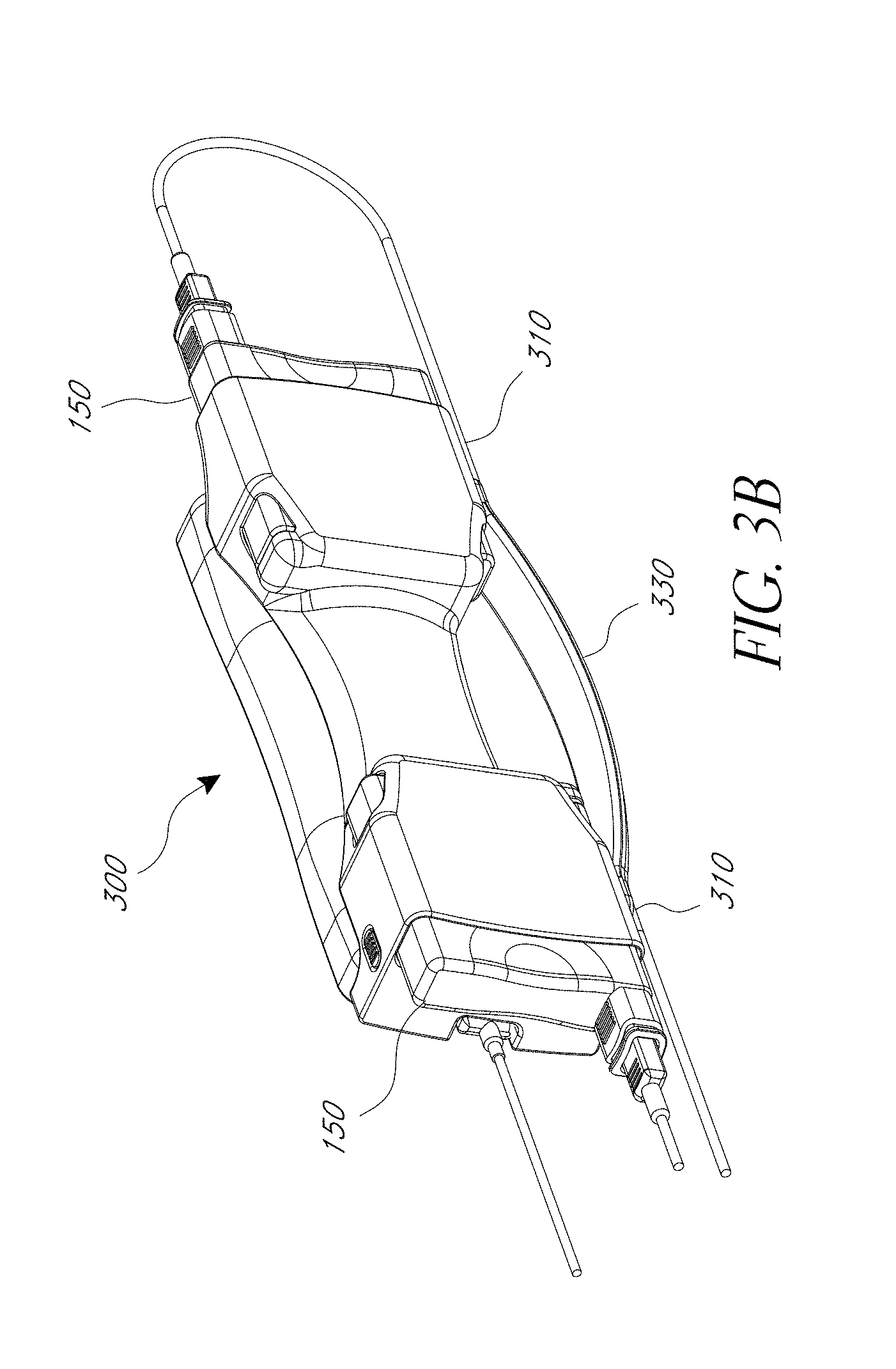
[0064] FIGS. 3A and 3B illustrate perspective views of an embodiment of a transport dock, carrier dock or transport cradle 300. In one embodiment, the transport dock 300 serves as a holder, cradle or a carrier for a handheld monitor 110. For example, the transport dock 300 can include an attachment mechanism to a bed frame, stand, ambulance interior, and/or other mounting surface. In one embodiment, the transport dock 300 expands the capability of a handheld monitor 110 by, for example, providing docking ports for expansion modules 150. In some embodiments, the expansion modules 150 includes a display 305 on one side, where the display remains exposed even after the expansion module is docked.
[0065] In one embodiment, the transport dock 300 is roughly a rectangular box shape and can include one or more docking ports 310, 320 on one or more faces or on one or more sides. The docking ports 310, 320 can receive one or more expansion modules 150 and/or one or more handheld monitors 110. For example, the front of the transport dock can include a docking port 320 for receiving eclectically and/or mechanically the handheld monitor 110. A display can be part of the transport dock. Alternatively, the display can be part of the handheld monitor. In the illustrated embodiment, the body of the transport dock 300 includes two expansion docking ports 310 for two expansion modules 150. In the illustrated embodiment, the docking ports 310 are arranged behind the handheld dock 320 in order to more efficiently use space and reduce the length of the assembled transport dock. The transport dock 300 can further include an integrated handle 330 for enhancing the portability of the transport dock 300. In one embodiment, the transport dock 300 is attachable to a docking station 120, for example, via a docking port 130.
[0066] In the illustrated embodiment, the expansion module 150 is configured for ease of installation and removal from the transport dock 300. An extraction handle 332 can be provided on the exposed side of the expansion module when docked. The extraction handle can be made of rubber or other high friction material. Raised textures can be formed on the surface of the extraction handle 332 to increase friction. In one embodiment, the extraction handle 332 is integrated into the expansion module and can include a cable port for receiving a cable connector 334. In another embodiment, the extraction handle 332 is part of the cable connector 334 and attaches to the expansion module 150 through a locking mechanism, such as a tab, latch or pin system. In one embodiment, the locking mechanism to the expansion module 150 can be articulated by pushing the cable connector 334 into the extraction handle 332 or by otherwise moving the connector relative to the handle. In some embodiments, a docking port 336 on the expansion module can be generally linearly aligned with an extraction handle 332 to allow the expansion module 150 to be pulled out of the transport dock 300 by applying an outward linear force on the extraction handle 332. The transport dock 300 can include a locking mechanism 338 that may need to be released before removing the expansion module 150.
[0067] The transport dock 300 can provide additional portability and/or functionality to a handheld monitor 110. For example, the transport dock 300 can increase the parameter monitoring capability of the handheld monitor 110 by providing an interface and/or data connection with the one or more expansion modules 150. In one embodiment, the expansion modules 150 for attachment to the transport dock 300 and connection to the monitor 110 can be selected based on the intended use. For example, a transport dock 300 for use with a patient with head trauma can include a EEG module while a transport dock 300 for use with a heart patient can include a cardiac output module. In one embodiment, the transport dock module 300 can provide an additional power source to the handheld monitor 110.
[0068] FIG. 3C illustrates a perspective view of another embodiment of a transport dock 340. The transport dock 340 includes a multi-module docking port 345 within the body, with an opening on one edge of the body for receiving multiple expansion modules 150. In one embodiment, the transport dock 340 includes another multi-module docking port 345 or other docking port for another monitoring component 350. For example, the monitoring component 350 can be a power source, such as a battery, for providing power during portable operation of the handheld monitor. The transport dock 340 includes docking port 355 for a mechanically and/or electrically receiving the handheld monitor 110 and a handle 360.
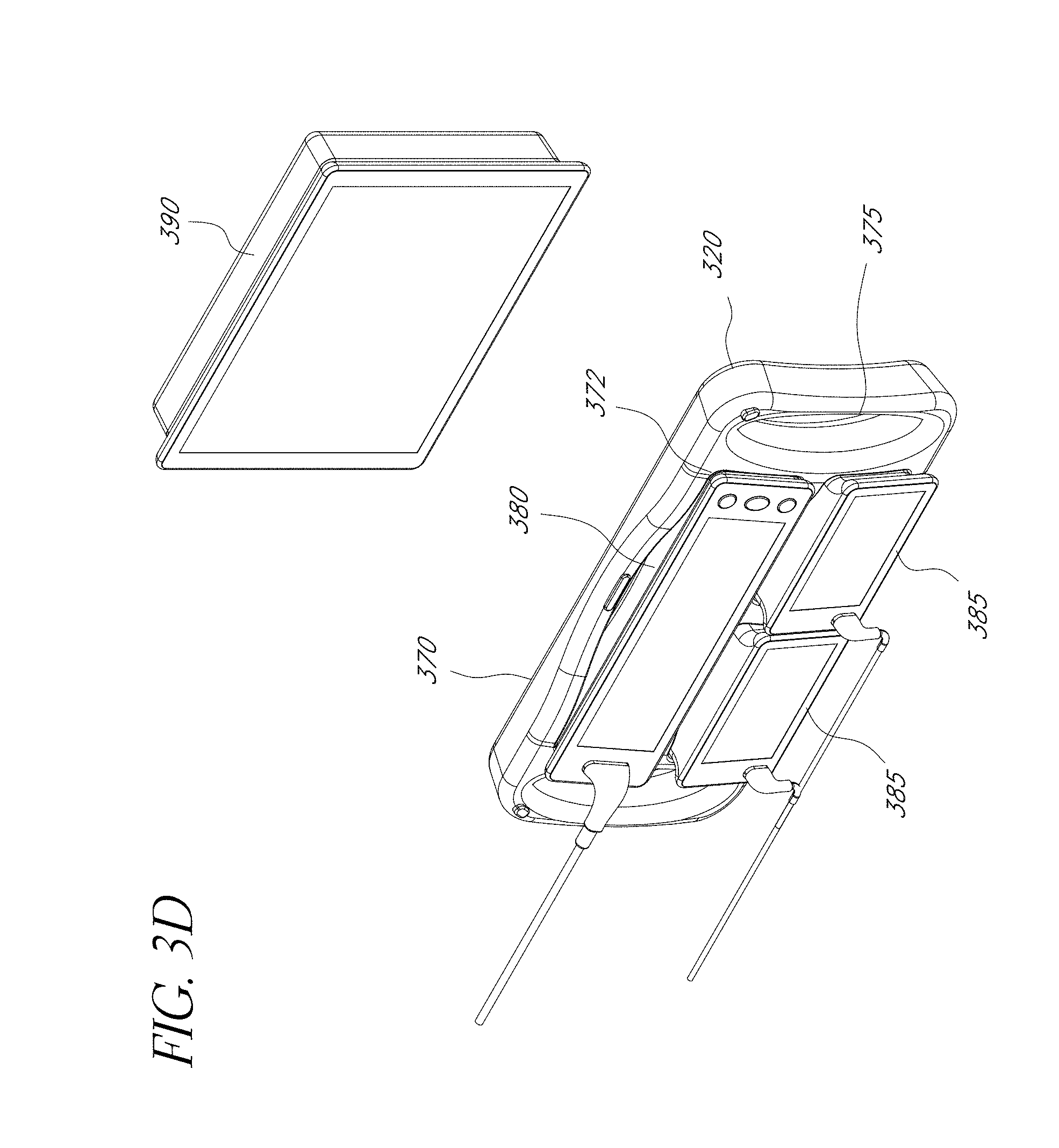
[0069] FIG. 3D illustrates a perspective view of another embodiment of a transport dock 370 with a multi-size docking port 372. In the illustrated embodiment, the transport dock is roughly rectangular shaped with handles 375 on opposite edges. On the front of the transport dock 370 is a multi-sized docking port 372 for different sized handheld monitors 380, 385, 390. In one configuration, the docking port 372 can fit four small handheld monitors 385. In another configuration, the docking port 372 can fit two medium handheld monitors 380. In another configuration, the docking port 372 can fit one large monitor 390. In another configuration, the docking port 372 can fit a combination of small 385, medium 385, and/or large handheld monitors 390. As will be apparent, the docking port 372 can be configured to receive different combinations and numbers of handheld monitors.
[0070] In one embodiment, the transport dock 370 can include multiple docking ports in addition to or instead of a multi-size docking port 372. For example, the transport dock 370 can include to one medium sized docking port and two small sized ports. As will be apparent, different combinations and numbers of port sizes may be used.
[0071] FIG. 3E illustrates a perspective views of another embodiment of a transport dock 392 with an attached docking arm 395. The docking arm 395 can be integrated or detachable from the transport dock. The docking arm 395 can be used to attach the transport dock 392 electrically and/or mechanically to a docking station 120.
[0072] FIGS. 4A-4F illustrate embodiments of a monitoring tablet. In some embodiments, the monitoring tablet is a transport dock with an integrated patient monitor.
[0073] In FIG. 4A, the tablet 405 is roughly rectangular shaped with handles 410 on opposite edges. The display 415 displays one or more parameter values and/or waveforms of monitored parameters. The tablet 405 can have one or more controls, such as buttons, dials, or a touch screen. The tablet 405 can include a wireless transmitter and/or receiver for communicating with a physiological sensor, patient monitor and/or docking station.
[0074] FIG. 4B illustrates a monitoring tablet 420 with a handle 410 on one edge and a docking port 425 for receiving a cable assembly 430 from a physiological sensor, docking station and/or patient monitor. As will be apparent, the handle 410 and docking port 425 can be located on any side of the monitoring tablet 420.
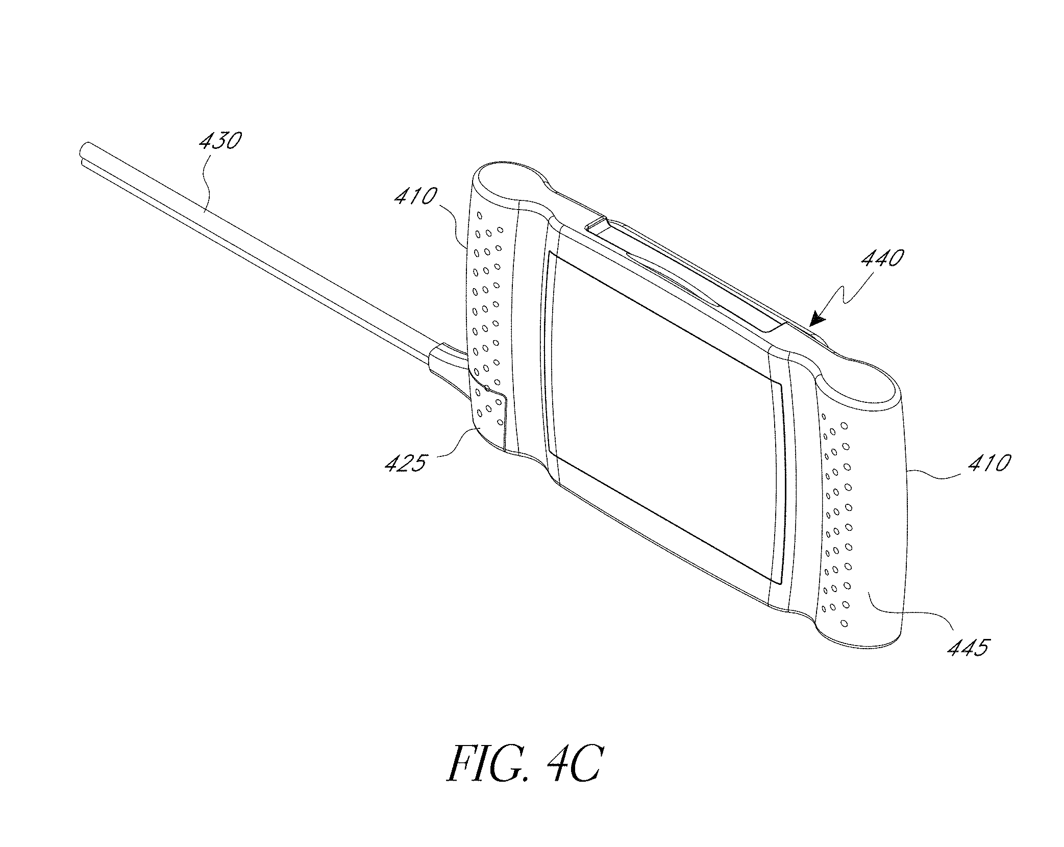
[0075] FIG. 4C illustrates another embodiment of a monitoring tablet 440. The monitoring tablet 440 includes handles along two, opposite sides 410. The handles 410 include a textured area 445, comprising bumps, protrusions, a mesh or web, or the like, for providing better grip for a user. In one embodiment, the textured area 445 comprises a rubberized grip. The handle 410 can include a docking port 425 for receiving a cable assembly 430.
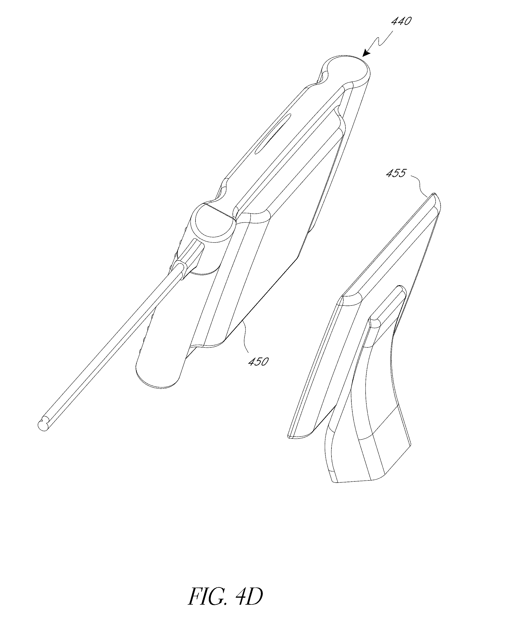
[0076] FIG. 4D illustrates an embodiment of the monitoring tablet 440 of FIG. 4C with a mounting surface 450 on the back for mounting the tablet 440 to a stand 455, mounting arm, or other mounting surface. In one embodiment, the monitoring tablet 440 attaches to a docking port 135 of a docking station 120. In one embodiment, the mounting surface 450 comprises input, output (I/O) and/or power connections, for example, for docking with a docking station.
[0077] FIGS. 4E-4F illustrate perspective and exploded views, respectively, of a monitoring tablet embodiment 460 having multiple expansion slots for expansion modules 465. In one embodiment, the parameters or screen image that would ordinarily be displayed on the module displays when undocked are available for viewing in a window, tab, or the like on the monitoring tablet display. For example, there could be a tab on the tablet display that, when touched, causes the parameters or screen image from a module to appear.
[0078] FIGS. 5A1-5D illustrate various docking station embodiments capable of receiving a transport dock, monitoring tablet, and/or handheld monitor. FIG. 5A1 illustrates the transport dock 370 of FIG. 3D attachable mechanically and/or electrically to a docking station 505 embodiment via a docking port 510. FIG. 5A2 illustrates an exploded view of the embodiment in FIG. 5A1.
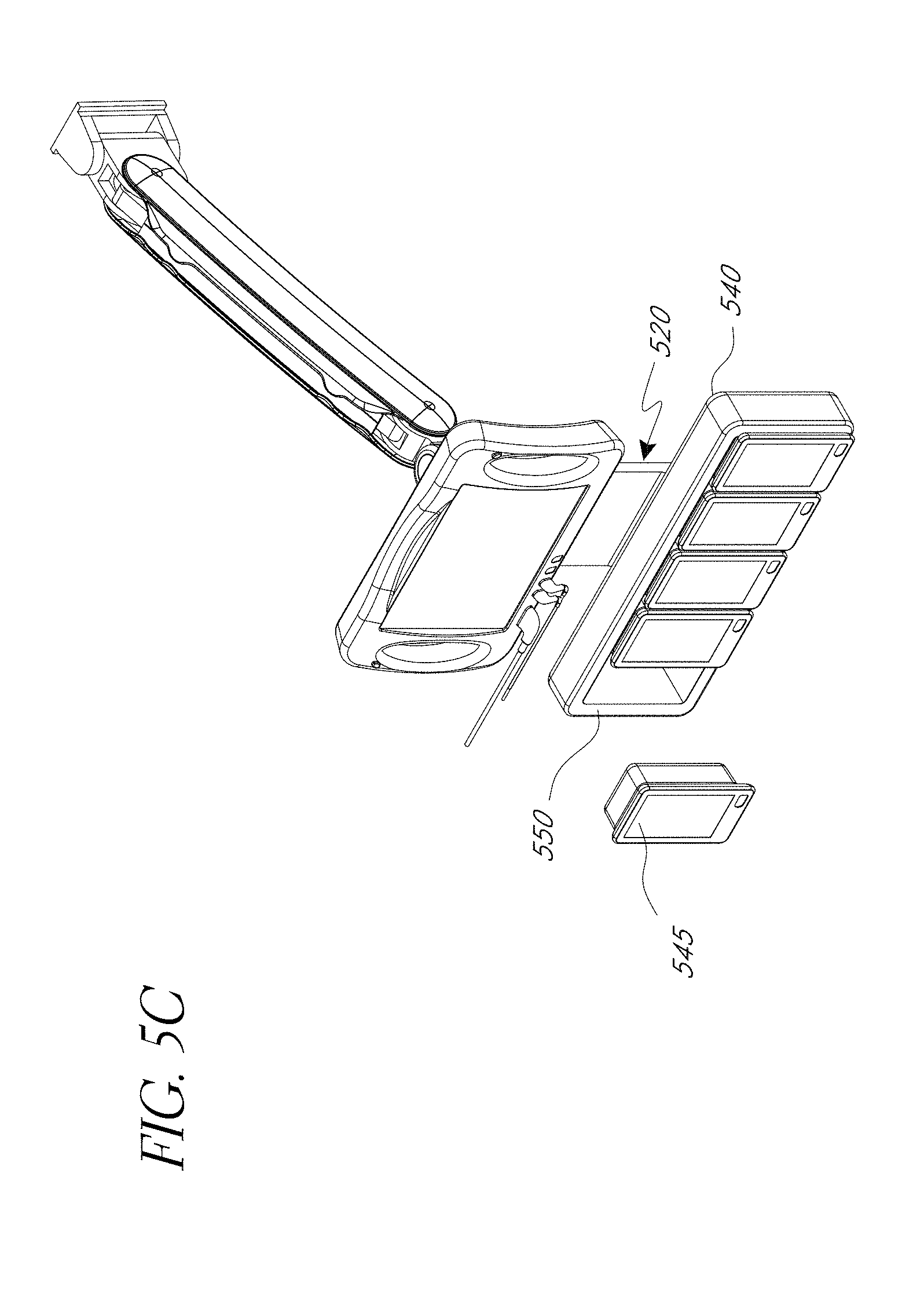
[0079] FIG. 5B illustrates a docking station embodiment 520 having docking ports for a monitoring tablet 530 and a transport dock 540. In one embodiment, the docking station 520 does not include an integrated patient monitor or display. The transport dock 540 can include multiple docking ports for receiving multiple portable monitors 545. The portable monitors 545 can be expansion modules with displays to increase the available display space. For example, additional portable monitors 545 can be added in order to measure and/or monitor additional parameters. In the illustrated embodiment, the docking station 520 is attached to a mounting arm.
[0080] FIG. 5C illustrates the transport dock 540 of FIG. 5B with a portable monitor 545 removed from its docking port 550.
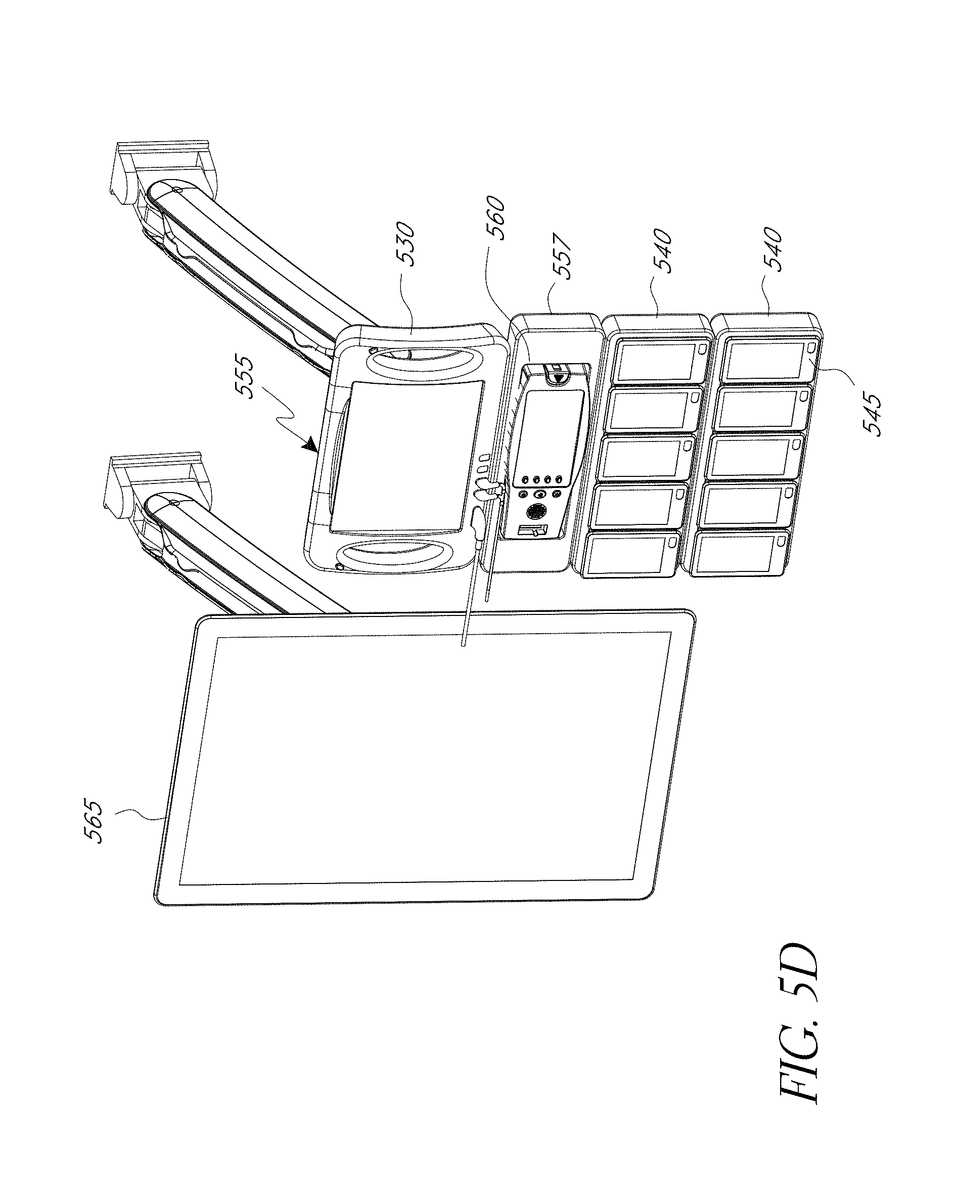
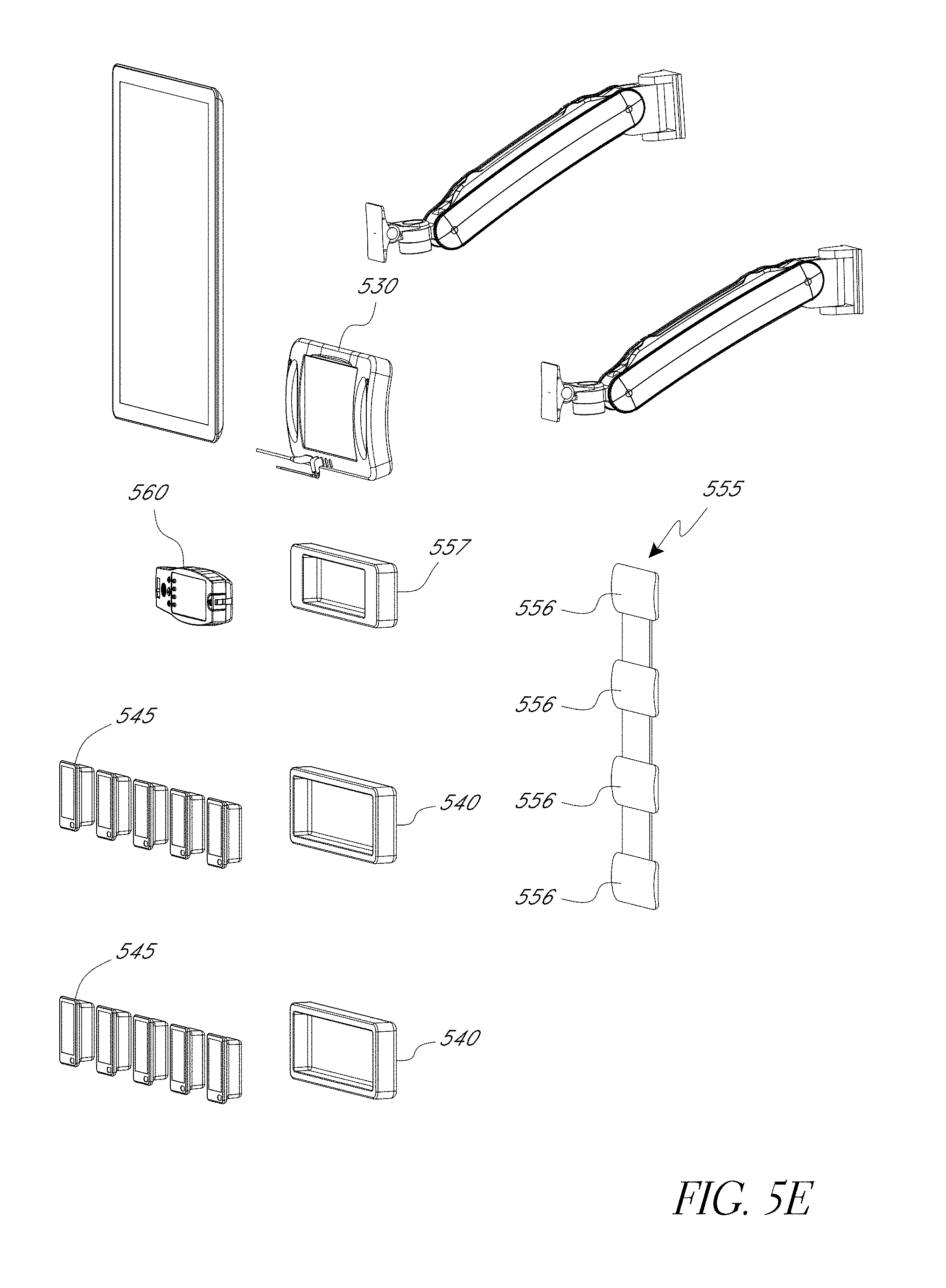
[0081] FIG. 5D illustrates a docking station embodiment 555 with docking ports for multiple transport dock 540, 557, multiple types of transport docks, and/or one or more monitoring tablets 530. FIG. 5E illustrates an exploded view of the docking station embodiment 555. In one embodiment, the transport docks 540, 557 can provide docking ports 556 for multiple types of handheld monitors 545, 560. In one embodiment, the handheld 560 is a Radical.RTM. or Radical-7.TM. handheld monitor.
[0082] In one embodiment, the docking station 555 operates in tandem or in communication with a patient monitor 565 or another docking station. The docking station 555 can communicate with the patient monitor 555 through a wired or wireless communications medium.
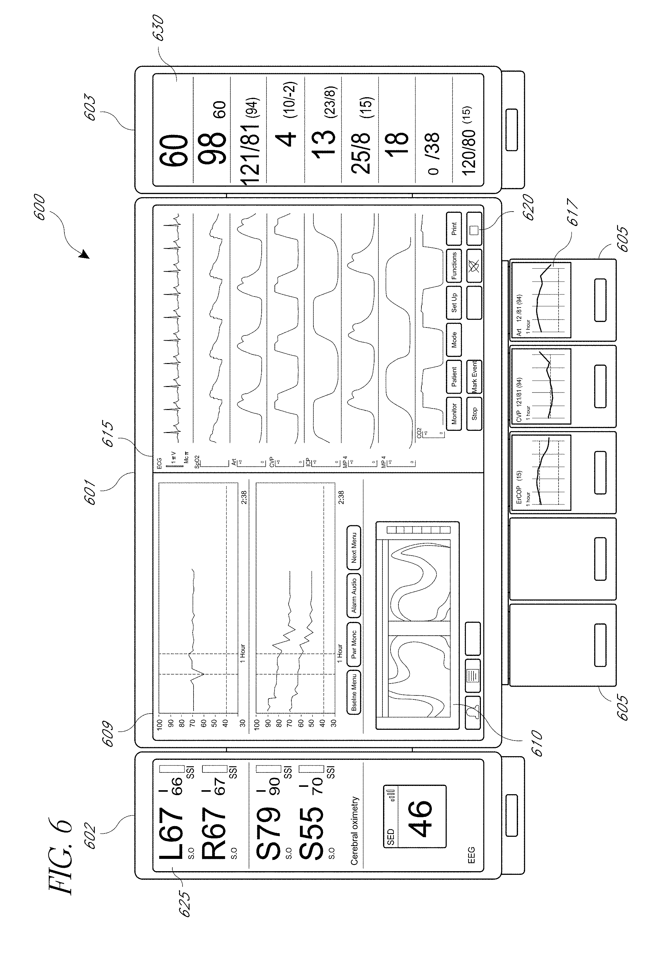
[0083] FIG. 6 illustrates a front view of the embodiment of the modular patient monitor 600 of FIGS. 2H-2J, displaying measurements for parameters across multiple displays. The multiple displays can be part of one or more components of the modular patient monitor 600, such as a first display 601 (e.g. primary or integrated display), one or more portable monitors 602, 603, and/or one or more expansion modules 605. Measurements can be spanned across the multiple displays, for example, by displaying a partial set of the measurements on the first display 601 and additional measurements on a portable monitor 602, 603. In one embodiment, instant readings, such as current numerical measurements 625, 630, can be displayed on one display (e.g. on the portable monitor display 625, 630) while measurements over time, such as waveforms 609, 615, 617 are displayed on another display (e.g. on the first display 601 or on an expansion module 605). Thus, a user can refer to one display for a summary of a status of a monitored patient, while referring to another display for more detailed information. Images 610 derived from the patient, such as ultrasound images, thermal images, optical coherence tomography (OCT) images can also be displayed on one or more displays.
[0084] In one embodiment, measurements of the parameters can be organized into different views that are shown on the displays of the patient monitor 600. For example, views can include a standard format, a tend-centric logically grouped format, or an expandable view where measurement screens are collapsed into a diagram or representation (e.g. the human body, brain, lungs, peripheries, or the like) that can be viewed in more detail by selecting sections of the diagram.
[0085] In one embodiment, one portable monitor 602 can be for a one part of the body, such as the head, measuring parameters for that particular part, (e.g., cerebral oximeter, EEG, core pulse CO-oximetry, pulse oximetry of the forehead, ear, or carotid, or the like) while another potable monitor 603 is for another part of the body, such as the periphery and lungs, and measuring parameters for that second part (e.g., pulse CO-Oximetry or pulse oximetry of the periphery or digit, RAM, ECG, blood pressure, organ, liver or kidney oximetry, or the like).
[0086] Measurements on the display or other portions of the display can be highlighted, colored, flashed, or otherwise visually distinguished in order to alert or notify users of important or irregular measurements. For example, normal measurements can be displayed in green, abnormal in yellow and critical measurements in red. As discussed above, measurements can be displayed for many different parameters, such as EEG, BP, ECG, temperature, cardiac output, oxygen saturation (SpO.sub.2), pulse rate (PR), perfusion index (PI), signal quality (SiQ), a pulse waveform (pleth), as well as other parameters.
[0087] In some embodiments, a user can select which measurements to display, drop, and/or span using controls 620 on the modular patient monitor 600. The controls 620 can be physical controls (e.g. buttons, switches) or virtual controls (e.g. touch screen buttons). In some embodiments, the monitor 600 can have an algorithm for selecting measurements to display, drop, and/or span, such as by ranking of measurements, by display templates or by user preferences. In some embodiments, the controls can alter, initiate, suspend or otherwise change the procedures being performed on the patient. For example, an anesthesiologist may increase the level of anesthesia provided to the patient or a doctor can begin therapy treatment by inputting commands through the controls. In one embodiment, the patient monitor 600 may request identification (e.g. login, password, ID badge, biometrics, or the like) before making any changes.
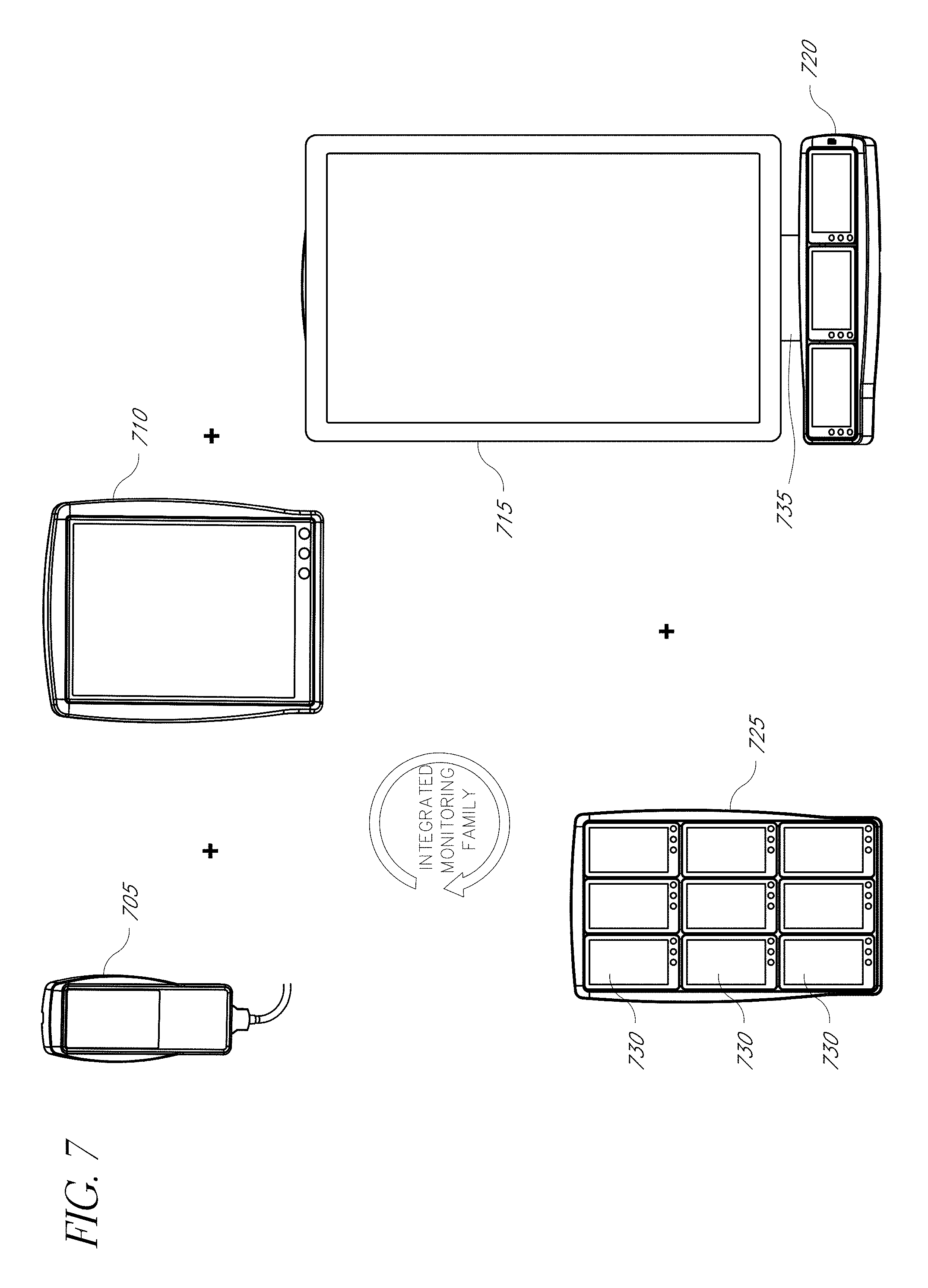
[0088] FIG. 7 illustrates a general block diagram of an embodiment of a physiological monitoring family. FIG. 7 illustrates a physiological monitoring family 700 having a handheld monitor 705, a tablet monitor 710, a full-sized display 715, a 1.times.3 module rack or dock 720, a 9.times.9 module rack or dock 725, and corresponding monitor modules 730 (e.g. expansion module or handheld monitor). In some embodiments, one or more components can function, alone or in combination, as a patient monitor. In an embodiment, the monitoring family 700 can be in communication with a sensor array, which can include optical and acoustic sensors for measuring blood parameters, such as oxygen saturation; and acoustic parameters, such as respiration rate; and for body sound monitoring. In an embodiment, sensor data is transmitted via cables or wirelessly to the monitors or to local or wide area hospital or medical networks.
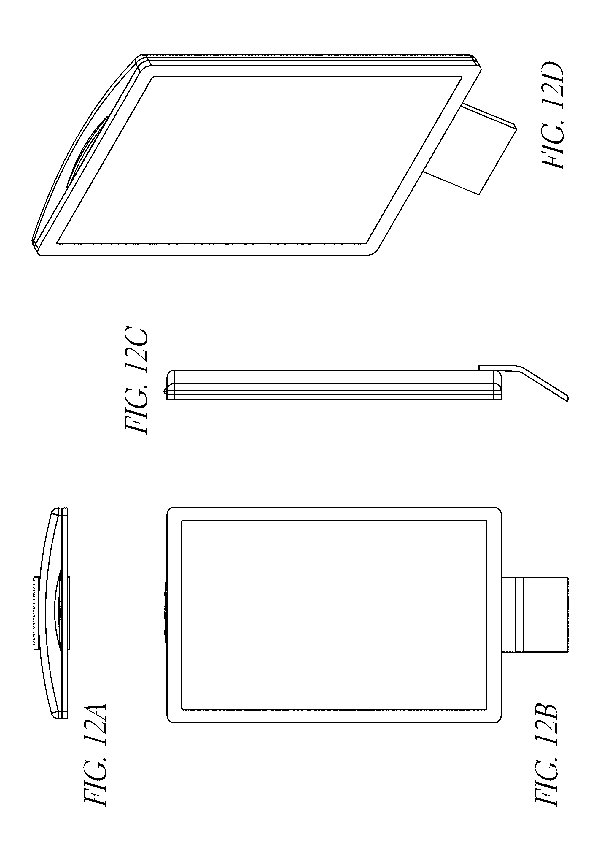
[0089] In one embodiment, the large display 715 integrates data from a tablet 710, hand held 705 or various module monitors 730. In one embodiment, the large display includes a patient monitor and provides a platform for an enhanced situational awareness GUI. A display bracket 735 allows removable attachment of various devices, including a 1.times.3 rack 720 or a tablet monitor 710, to name a few. The rack embodiment contains one or more removable OEM monitor, control or display modules 730. These embodiments can function as a multiple parameter monitor having flexible user interface and control features. In one embodiment, the tablet monitor 710 has a removable user interface portion for the monitor (e.g. remote control or other input device) and/or touch screen controls for the display.
[0090] FIGS. 8A-E are top, front, bottom, side and perspective views, respectively, of the handheld monitor embodiment 705 of FIG. 7.
[0091] FIGS. 9A-D are top, front, side and perspective views, respectively, of the tablet monitor embodiment 710 of FIG. 7.
[0092] FIGS. 10A-E are top, front, side, perspective and exploded views, respectively, of the 3.times.3 rack embodiment 725 of FIG. 7 with mounted display modules. In one embodiment, the mounted display modules are multiple single parameter monitor modules. In an embodiment, each removable module has a wired or wireless network connection (e.g., 802.11, BLUETOOTH or the like), a 4.3'' display and a battery for standalone operation. This allows each module to be used as a single parameter transport monitor, as well as used as part of a larger modular patient monitoring system. In some embodiments, the module mechanical form and fit and the electrical/electronic interfaces are standardized to advantageously allow for the integration of OEM acute care monitoring, control and display technologies into the physiological monitoring family.
[0093] FIGS. 11A-E are top perspective, front, side, and exploded views, respectively, of a 1.times.3 rack embodiment 720 of FIG. 7 with mounted monitor, control and/or display modules.
[0094] FIGS. 12A-D are top, front, side and perspective views, respectively, of the large display 715 and display bracket 735 of FIG. 7.
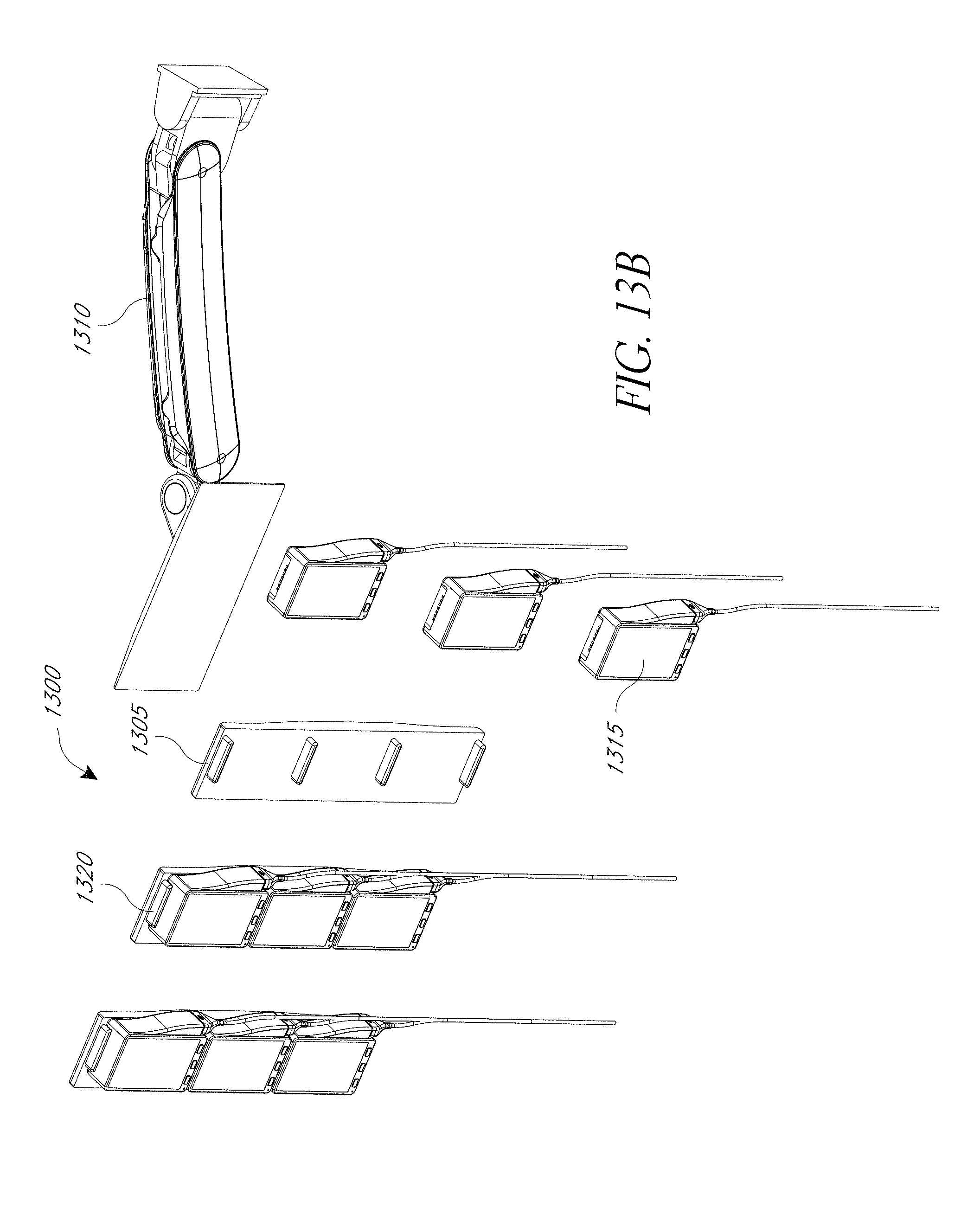
[0095] FIGS. 13A-B are perspective and exploded views of another embodiment of a modular patient monitor 1300. In the illustrated figure, a docking station 1303 is attached to a movable mount or arm 1310 on its back side, while its front side comprises multiple docking ports 1320 for multiple monitor modules 1315. The illustrated monitor module 1315 includes a cable port on the side that can provide improved cable management. For example, by having the port on the side, sensor cables that attach to the monitor can be kept from blocking the display. In one embodiment, the docking station 1303 can comprise a 3.times.3 rack with sufficient space between columns to allow cables to run between the columns. This can improve organization and cable management for the modular patient monitor 1300. In an embodiment, the docking station 1303 is comprised of multiple module racks (e.g. three 1.times.3 module racks) attached together.
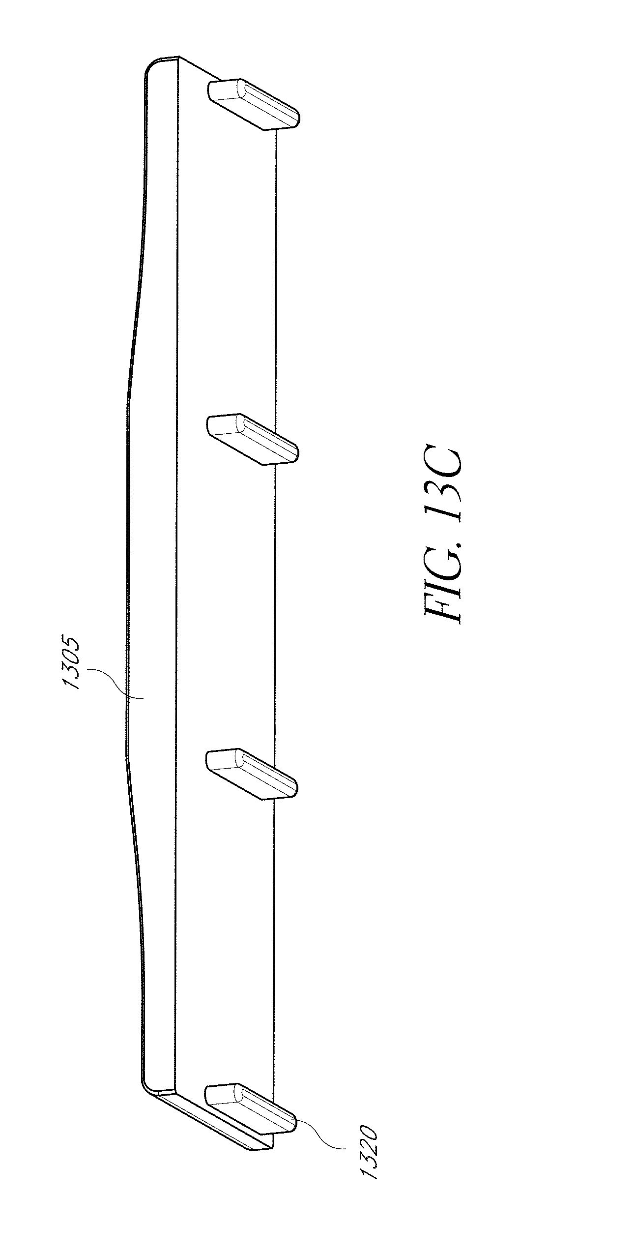
[0096] FIG. 13C illustrates a perspective view of an embodiment of a 1.times.3 module rack. The illustrated module rack 1305 includes raised supports 1320 for supporting and/or attaching to one or more of the edges (e.g. top and bottom) of a handheld monitor or expansion module. The supports 1320 can include connections for providing power and/or data communication to the handheld monitor or expansion module.
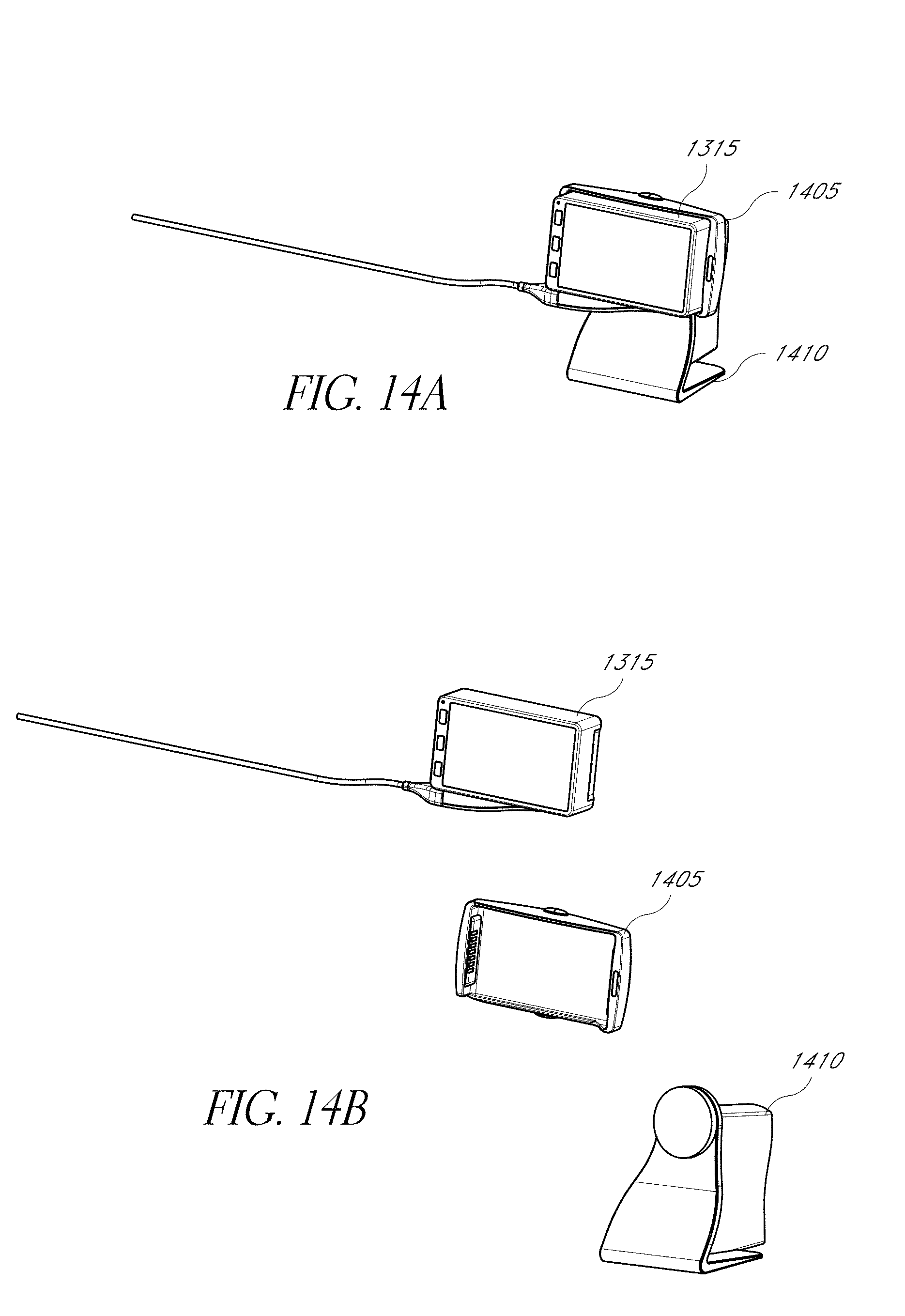
[0097] FIGS. 14A-B illustrates an embodiment of the monitor module 1315 of FIG. 13A-13B used in combination with a single port dock 1405. The dock 1405 can include a mounting point for a stand 1410. In one embodiment, the monitor module 1315 can be directly connected to the stand 1410 without using the dock 1405.
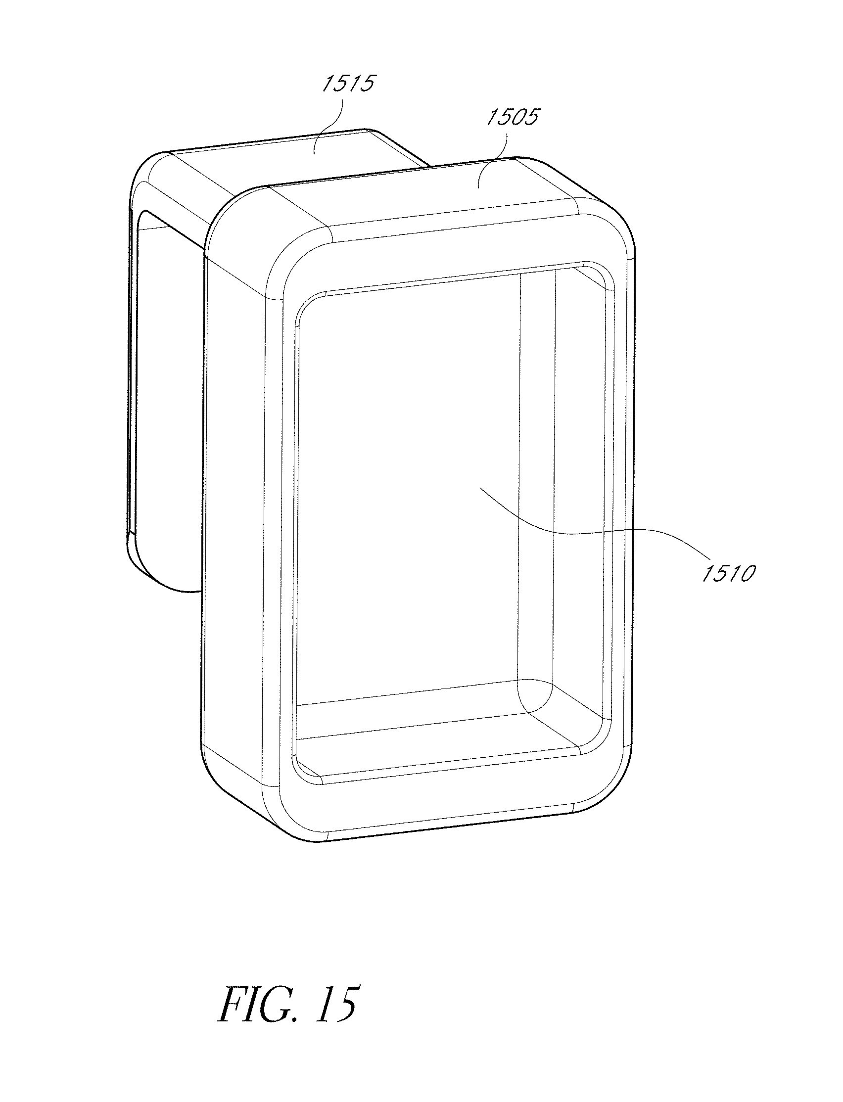
[0098] FIG. 15 illustrates an embodiment of a single port dock 1505. The dock can include a docking port 1510 for a module monitor and an attachment clip or hook 1515. The attachment clip 1515 can be used to attach the dock 1505 to a bed, stand, or other attachment point.
[0099] Modular patient monitors, transport docks, and docking stations have been disclosed in detail in connection with various embodiments. These embodiments are disclosed by way of examples only and are not to limit the scope of the claims that follow. One of ordinary skill in art will appreciate many variations and modifications. Indeed, the novel methods and systems described herein can be embodied in a variety of other forms; furthermore, various omissions, substitutions and changes in the form of the methods and systems described herein can be made without departing from the spirit of the inventions disclosed herein. The claims and their equivalents are intended to cover such forms or modifications as would fall within the scope and spirit of certain of the inventions disclosed herein.
[0100] One of ordinary skill in the art will appreciate the many variations, modifications and combinations possible. For example, the various embodiments of the patient monitoring system can be used with sensors that can measure any type of physiological parameter. In various embodiments, the displays used can be any type of display, such as LCDs, CRTs, plasma, and/or the like. Further, any number of handheld monitors and/or expansion modules can be used as part of the patient monitoring system. In some embodiments, the expansion modules can be used instead of handheld monitors and vice versa. Further, in some embodiments, parameters described above as measured by a monitor can be enabled by an expansion module and/or monitors can have built functionally to monitor parameters described as enabled by an expansion module. In some embodiments, the modular monitoring system 100 can use multiple types of docking ports to support various different monitoring components. Embodiments of the transport dock can support any number of handheld monitors and/or expansion modules, depending on the configuration of the dock.
[0101] In certain embodiments, the systems and methods described herein can advantageously be implemented using computer software, hardware, firmware, or any combination of software, hardware, and firmware. In one embodiment, the system includes a number of software modules that comprise computer executable code for performing the functions described herein. In certain embodiments, the computer-executable code is executed on one or more computers or processors. However, a skilled artisan will appreciate, in light of this disclosure, that any module that can be implemented using software can also be implemented using a different combination of hardware, software or firmware. For example, such a module can be implemented completely in hardware using a combination of integrated circuits. Alternatively or additionally, such a module can be implemented completely or partially using specialized computers or processors designed to perform the particular functions described herein rather than by general purpose computers or processors.
[0102] Moreover, certain embodiments of the disclosure are described with reference to methods, apparatus (systems) and computer program products that can be implemented by computer program instructions. These computer program instructions can be provided to a processor of a computer or patient monitor, special purpose computer, or other programmable data processing apparatus to produce a machine, such that the instructions, which execute via the processor of the computer or other programmable data processing apparatus, create means for implementing the acts specified herein to transform data from a first state to a second state.
[0103] Conditional language used herein, such as, among others, "can," "could," "might," "may," "e.g.," and the like, unless specifically stated otherwise, or otherwise understood within the context as used, is generally intended to convey that certain embodiments include, while other embodiments do not include, certain features, elements and/or states. Thus, such conditional language is not generally intended to imply that features, elements and/or states are in any way required for one or more embodiments or that one or more embodiments necessarily include logic for deciding, with or without author input or prompting, whether these features, elements and/or states are included or are to be performed in any particular embodiment.
* * * * *
D00000
D00001
D00002
D00003
D00004
D00005
D00006
D00007
D00008
D00009
D00010
D00011
D00012
D00013
D00014
D00015
D00016

D00017
D00018

D00019

D00020

D00021
D00022
D00023
D00024
D00025

D00026

D00027

D00028
D00029
D00030
D00031
D00032
D00033

D00034

D00035

D00036

D00037

D00038

D00039
D00040

D00041
D00042
D00043
D00044
XML
uspto.report is an independent third-party trademark research tool that is not affiliated, endorsed, or sponsored by the United States Patent and Trademark Office (USPTO) or any other governmental organization. The information provided by uspto.report is based on publicly available data at the time of writing and is intended for informational purposes only.
While we strive to provide accurate and up-to-date information, we do not guarantee the accuracy, completeness, reliability, or suitability of the information displayed on this site. The use of this site is at your own risk. Any reliance you place on such information is therefore strictly at your own risk.
All official trademark data, including owner information, should be verified by visiting the official USPTO website at www.uspto.gov. This site is not intended to replace professional legal advice and should not be used as a substitute for consulting with a legal professional who is knowledgeable about trademark law.