A Flow Base System For Subsea Wells
HESTETUN; Steinar Lindermann ; et al.
U.S. patent application number 16/472580 was filed with the patent office on 2019-10-24 for a flow base system for subsea wells. The applicant listed for this patent is Vetco Gray Scandinavia AS. Invention is credited to Mohammad Hasan ALI, Tor Alexander FJELDLY, Steinar Lindermann HESTETUN, Craig Wilson JOHNSTONE, Kare TOLO, Paul William WHITE.
| Application Number | 20190323325 16/472580 |
| Document ID | / |
| Family ID | 60972212 |
| Filed Date | 2019-10-24 |


| United States Patent Application | 20190323325 |
| Kind Code | A1 |
| HESTETUN; Steinar Lindermann ; et al. | October 24, 2019 |
A FLOW BASE SYSTEM FOR SUBSEA WELLS
Abstract
A flow base system (1) for subsea wells is disclosed, the flow base system comprising a header pipe (2) for production fluid extended through the flow base system, wherein from opposite sides of the header pipe (3) a set of flow base modules (2), respectively, is connected for supply of production fluid to the header pipe (3) via individual branch pipes (10) connecting the header pipe (3) with a Christmas tree (XT) interface (11) arranged for vertical connection to an XT respectively. The flow base system (1) is installed in a well template structure (18), wherein a flow base module (2) respectively is inserted into each well slot (S1-S4) formed in the well template structure (18).
| Inventors: | HESTETUN; Steinar Lindermann; (Sandvika, NO) ; TOLO; Kare; (Sandvika, NO) ; JOHNSTONE; Craig Wilson; (Aberdeen, GB) ; WHITE; Paul William; (Aberdeen, GB) ; ALI; Mohammad Hasan; (Sandvika, NO) ; FJELDLY; Tor Alexander; (Sandvika, NO) | ||||||||||
| Applicant: |
|
||||||||||
|---|---|---|---|---|---|---|---|---|---|---|---|
| Family ID: | 60972212 | ||||||||||
| Appl. No.: | 16/472580 | ||||||||||
| Filed: | December 21, 2017 | ||||||||||
| PCT Filed: | December 21, 2017 | ||||||||||
| PCT NO: | PCT/EP2017/084213 | ||||||||||
| 371 Date: | June 21, 2019 |
| Current U.S. Class: | 1/1 |
| Current CPC Class: | E21B 41/04 20130101; E21B 41/08 20130101; E21B 43/017 20130101 |
| International Class: | E21B 41/08 20060101 E21B041/08; E21B 43/017 20060101 E21B043/017; E21B 41/04 20060101 E21B041/04 |
Foreign Application Data
| Date | Code | Application Number |
|---|---|---|
| Dec 22, 2016 | NO | 20162048 |
Claims
1. A flow base system (1) for subsea wells comprising a template structure (18) with a header pipe (3) and a number of flow base structures (2), each flow base structure comprising a XT interface (11) connectable to a XT and wellhead, a set of flow base structures (2) being arranged on each side of the header pipe, each flow base structure being connected to the header pipe (3) via individual branch pipes, the flow base structures (2) being fixed to the well template structure (18).
2. The flow base system of claim 1, wherein the piping of the flow base system (1) is fixed to the template structure (18).
3. The flow base system of claim 1, wherein the piping of the flow base system is partly fixed to the flow base structures (2).
4. The flow base system of claim 1, wherein the valves of the system are removable.
5. The flow base system of claim 1, comprising two or more header pipes.
6. The flow base system of claim 1, wherein the flow base modules (2) are essentially identical and the flow base modules on one side of the at least one header pipe (3) are turned 180.degree. in relation to the orientation of the flow base modules on the other side of the at least one header pipe.
7. The flow base system of claim 1, wherein each flow base module (2) comprises a well insert (14) in fixed relation to guiding means (15) arranged for guidance of an XT during landing and installation.
8. The flow base system of claim 4, wherein the guiding means (15) is realized as guide posts/pillars or as funnel-equipped tubes rising from a flow base support (13), in which the branch pipes (10) and valves as well as XT interfaces (11, 38) are supported.
9. The flow base system of claim 1, wherein a singular isolation valve (12) on each branch pipe (10) is controllable for opening the branch pipe for flow of production fluid into the one or more header pipes (3).
10. The flow base system of claim 1, wherein coupling means (7) is arranged in an end (4) of one or more header pipes (3) for connecting to external subsea equipment.
11. The flow base system of claim 10, wherein an isolation valve (6) in said end (4) of the one or more header pipes (3) is controllable for through flow of production fluid from external equipment.
12. The flow base system of claim 1, wherein a valve control interface (29) is installed for intervention by a remotely operated vehicle (ROV) or diver.
13. The flow base system of claim 1, wherein a well intervention system (35) is installed essentially in parallel with the production fluid pipework.
14. The flow base system of claim 13, wherein the well intervention system (35) comprises at least one header pipe (36) with branch pipes (37) extended to each flow base module (2).
15. The flow base system of claim 13, wherein the fluid of the well intervention system is supplied via an umbilical (32) to an umbilical termination assembly (33) associated with the flow base system.
16. The flow base system of claim 1, wherein a flow base module (2) comprises an extension (16) for connecting to an external supply of production fluid via a jumper pipe.
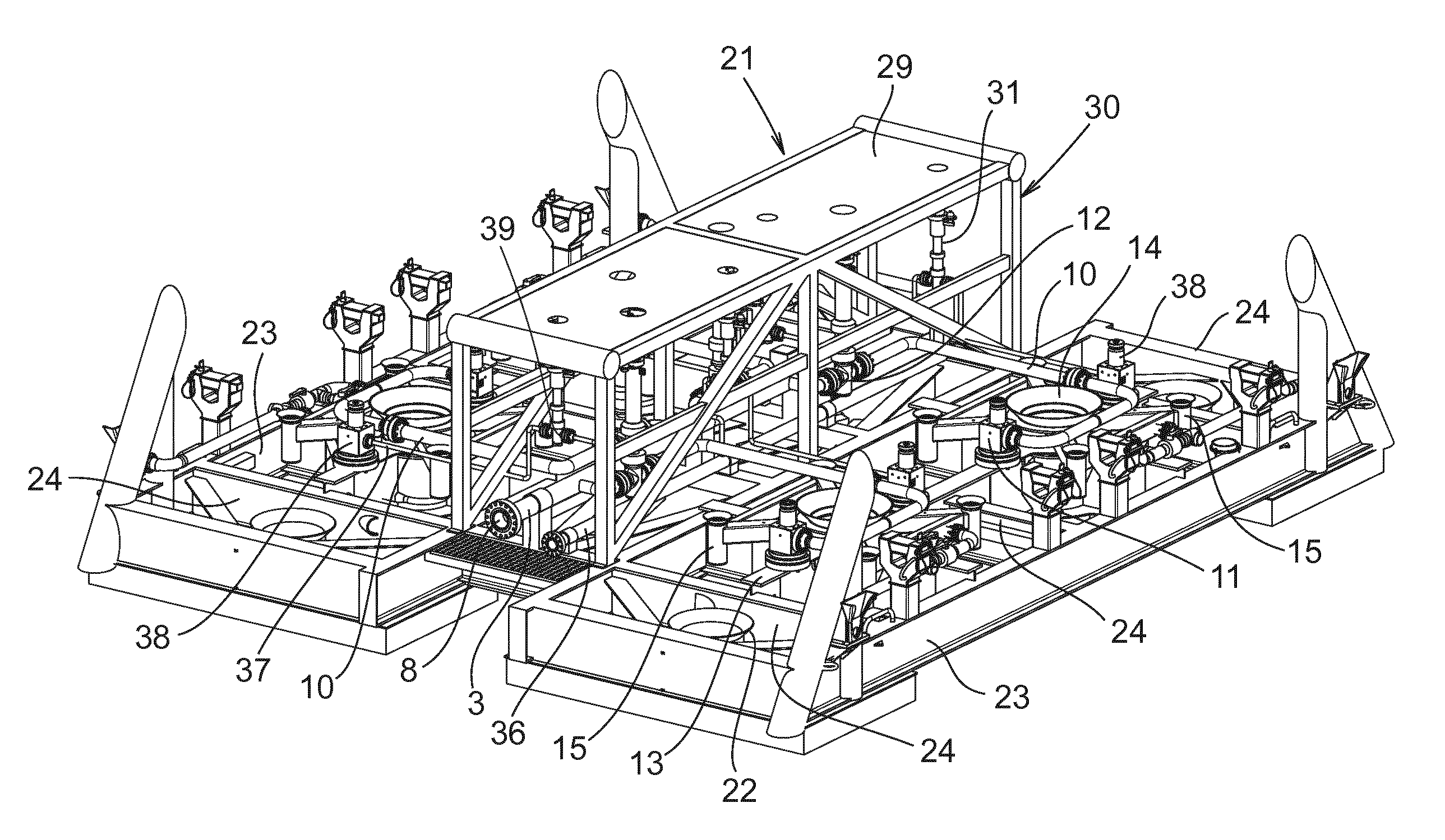
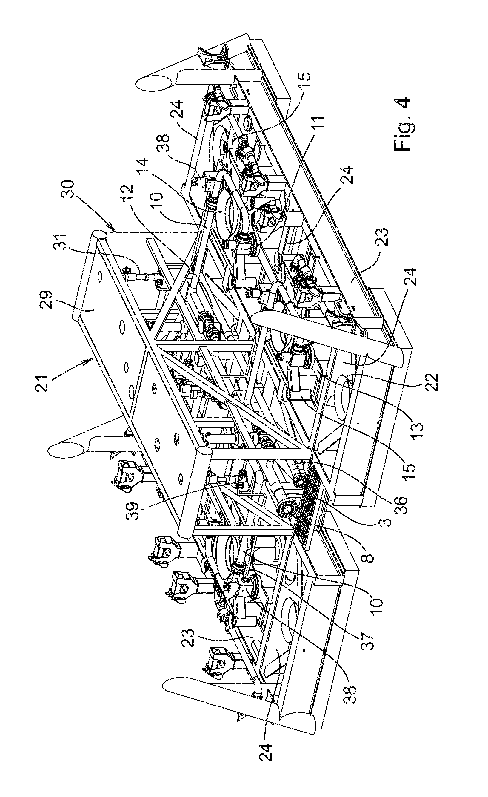
Description
TECHNICAL FIELD OF THE INVENTION
[0001] The present invention relates to a flow base system for subsea wells.
BACKGROUND AND PRIOR ART
[0002] The infrastructure of subsea hydrocarbon production fields typically comprises rigid and flexible piping and manifolds to collect production fluid from subsea wells. Subsea wells can be grouped in template solution, or spread out as standalone satellite wells regularly/irregularly distributed over the field. If wells can be grouped closely together, templates can be used for controlling the spacing between the wells. For the purpose of this disclosure, subsea wells which are closely grouped and guided in a template will be named template wells.
[0003] In general terms, a template is a structure which is placed on the seabed to provide guidance and support for other equipment such as drilling and completion equipment, wellheads, Christmas trees (XT), manifolds and pipeline connection equipment.
[0004] A production well template is a welded structure that supports manifold piping and valves for production fluid from wells which are grouped together at a single seabed location. The number of wells is limited by the size of the well template, which has an individual section or slot for each well connected to the template. Typical sizes include 2, 4, 6 and 8 slot configurations.
[0005] Template installation typically includes landing of a prefabricated piping deck onto the template. The piping deck typically includes the flowlines and valves necessary to conduct production fluid from the template, as well as the hydraulic lines required to operate the manifold and XT valves. Since maintenance and repairs on deep water equipment requires implementation of ROV-assisted structures, the piping deck, e.g., may be separately retrievable in order to avoid dismantling of the entire production system in case of damage to the piping components.
[0006] In shallow water installations, at water depths less than 200 m, diver-assisted intervention is possible and ROV-related structures are not necessary. However, there is a need for structures with fewer components to simplify intervention procedures.
[0007] There is also a constant need for more compact configurations on subsea structures. For shallow water installations, the production structures may be situated in fishery zones, with e.g. trawlers towing trawls on the seabed. To minimize conflict between oil and gas industry and fishing industry, it is an advantage to arrange oil production modules in compact structures and minimize the footprint on the seabed. The presented flow base system seeks to meet this challenge by arranging production modules that are normally spread out on the seabed into one compact structure.
[0008] In template structures there are also challenges related to tolerances when a large number of different structures or modules have to be fitted to each other and connected on the seabed. The meet the tolerance requirements, large piping spools are used to obtain sufficient flexibility in the piping structures in the field. As more of the production modules are assembled in one structure, the tolerance requirements are minimized due to a decreased need for piping.
SUMMARY OF THE INVENTION
[0009] It is an object of the present invention to provide a non-complex, low cost flow base system for subsea wells while also permitting tying-in of standalone wells and clusters of wells of an existing infrastructure.
[0010] It is another object of the present invention to provide a flexible flow base system that will fit in most common subsea field layout architectures.
[0011] Still other objects include the provision of a versatile flow base system which permits implementation of, e.g., pigging modules and well intervention systems.
[0012] One or more of these objects is met in a flow base system for subsea wells, the system comprising a header pipe for production fluid extended through the flow base system, wherein from opposite sides of the header pipe a set of flow base modules, respectively, is connected for supply of production fluid to the header pipe via individual branch pipes connecting the header pipe with a coupling interface arranged for vertical connection to a Christmas tree (XT) respectively. The flow base system is installed in a frame structure similar to a well template structure, such that a flow base module respectively is inserted into the well slots formed in the frame structure. This flow base system permits protection of the flow base components under a common top cover for the frame structure. This embodiment is also a compact and cost saving solution which combines one singular protection structure with a non-complex piping and instrumentation diagram (P&ID).
[0013] In other words, a flow base system for subsea wells is disclosed that comprises a template structure with a header pipe and a number of flow base structures, each flow base structure comprising a XT interface connectable to a XT and wellhead, a set of flow base structures being arranged on each side of the header pipe, each flow base structure being connected to the header pipe via individual branch pipes, the flow base structures being fixed to the well template structure.
[0014] Furthermore, in preferred embodiments, the piping of the flow base system is fixed to the template structure. The piping of the flow base system can also be partly fixed to the flow base structures. However, it is advantageous to enable a small float in the piping to allow for tolerance misalignment to be adjusted. To enable service, maintenance or replacement of elements, all valves of the system are removable.
[0015] In some embodiments the flow base system comprises two or more header pipes.
[0016] The described use of flow base structures facilitates extensive use of standard components in a streamlined building process. This benefits to reduced time for installation and testing and thereby cost savings. The described design also facilitates upscaling or downscaling of the system.
[0017] In some embodiments, each flow base structure comprises a well insert in fixed relation to guiding means arranged for guidance of an XT during landing and installation.
[0018] In some embodiments, the guiding means is realized as guide posts or pillars or as funnel-equipped tubes rising from a flow base support, in which the branch pipes and valves as well as XT interfaces are supported.
[0019] In some embodiments, a singular isolation valve on each branch pipe is controllable for opening the branch pipe for flow of production fluid into the at least one header pipe. The concept of providing a single barrier results in simplified piping and control of the flow base system.
[0020] In some embodiments, coupling means is arranged in one end of the at least one header pipe for connecting to external subsea equipment. The arrangement of coupling means at one end of the header pipe or pipes, makes it possible to extend the subsea field through the flow base system. This significantly improves the flexibility in the layout of a subsea field using the described flow base system. By connecting a further production line to the flow base system, a production flow can flow through the flow base system.
[0021] The coupling means can also be used for coupling of a pig launcher/receiver to the flow base system.
[0022] In some embodiments, an isolation valve in the same end of the header pipe is controllable for through flow of production fluid from connected external equipment. As the flow base system combines flow base structures with a template structure, the flexibility with regard to where valves are places is improved.
[0023] The described use of coupling means provides the ability for tying-in standalone satellite wells or interconnected (daisy-chain) wells, and permits connection of another flow base system if appropriate. The embodiment also provides the ability of connecting a pig launcher or receiver in the said end of the header pipe.
[0024] In some embodiments, the flow base modules are essentially identical and the flow base modules on one side of the header pipe are turned 180.degree. in relation to the orientation of the flow base modules on the other side of the header pipe.
[0025] In alternative configurations, the flow base modules on a first side of the header pipe may be mirrored layouts of the flow base modules on a second side of the header pipe. The first and second sides of the header pipe can advantageously be opposite sides of the header pipe. The advantage of standardization through the repeated use of identical components can still be enjoyed.
[0026] Operational control is distributed within the flow base system from an umbilical termination assembly (UTA) associated with the flow base system. This embodiment avoids control tubing since flying leads or cables can be used for distribution of hydraulic fluid and/or electrical power. Thus, XT control within the flow base system is distributed from the UTA via hydraulic and electric flying leads/cables.
[0027] In some embodiments, a valve control interface is installed for intervention by a remotely operated vehicle (ROV) or a diver. This feature can provide redundancy in case other operational control fails.
[0028] The XT control in the system can be distributed within the flow base system from an umbilical termination assembly associated with the flow base system.
[0029] Furthermore, the XT control can be distributed from the umbilical termination assembly via hydraulic and/or electric flying leads.
[0030] In some embodiments, a well intervention system is installed essentially in parallel with the production fluid pipework. The well intervention system comprises at least one header pipe with branch pipes extended to each flow base structure respectively. The fluid of the well intervention system can be supplied via an umbilical to an umbilical termination assembly associated with the flow base system. The umbilical termination assembly (UTA) can be coupled directly to the XTs on each flow base structure.
[0031] The well intervention system allows for supply of gas for enhanced lift of production fluid, or for supply of injection chemicals to the well. The flow base module may thus each comprise two vertical connection systems for the production fluid and for gas lift/chemicals respectively.
[0032] Each flow base module of the flow base system comprises a well insert in fixed relation to guiding means arranged for guidance of an XT during landing and installation.
[0033] The guiding means can be realized as guide posts/pillars or as funnel-equipped tubes rising from a flow base support, in which the branch pipes and valves as well as the XT interfaces are supported.
[0034] The flow base structure may comprise an extension for connecting to an external supply of production fluid via a jumper pipe. This configuration extends substantially the possibility of tying-in external singular or daisy-chain wells in an existing production field architecture.
SHORT DESCRIPTION OF THE DRAWINGS
[0035] Embodiments of the invention will be further explained below with reference made to the drawings. In the drawings:
[0036] FIG. 1 is a schematic view illustrating the flow base system.
[0037] FIG. 2 is a first perspective view of a subsea well template in which the flow base system is integrated.
[0038] FIG. 3 is a second perspective view of the subsea well template in which the flow base system is integrated,
[0039] FIG. 4 is a partially broken away perspective view corresponding to FIG. 2, showing details of the flow base system installed in the subsea well template.
DETAILED DESCRIPTION OF PREFERRED EMBODIMENTS
[0040] With reference made primarily to FIG. 1, a flow base system 1 comprises a set of flow base modules 2 arranged on opposite sides of a header pipe 3 for production fluid. The header pipe 3 extends through the flow base system from a first or upstream end 4 to a second or downstream end 5 as seen in the direction of flow F through the header pipe. The first end 4 is optionally connectable to external equipment for transport via the header pipe 3. The second end is the discharge end from which production fluid is discharged downstream.
[0041] A header isolation valve 6 is arranged in the first end of the header pipe, which also in the same end carries coupling means 7 for connecting to an external supplier of production fluid or to other subsea equipment. These external units can be another flow base system, a standalone satellite well or interconnected daisy-chain wells, or a pigging launcher/receiver e.g. In the discharge end 5, the header pipe carries coupling means 8, such as a flange coupling e.g., arranged for connecting the flow base system to a pipeline, a jumper pipe or to other downstream equipment for fluid transport. The header pipe 3 further comprises a number of pipe joints 9, especially T-couplings 9 through which the flow base modules 2 are connected to the header pipe 3 at mutually spaced locations along the header pipe.
[0042] Each flow base module 2 comprises a branch pipe 10 connecting the header pipe with an XT tree interface 11. An isolation valve 12 on the branch pipe is controllable for opening the branch pipe for flow of production fluid into the header pipe.
[0043] The isolation valves 6 and 12 are on/off valves, and can be realized as gate valves e.g.
[0044] The isolation valves 6, 12 are releasably connected to the pipe joints or T-branches 9 and branch pipes 10. If necessary, the isolation valves 6, 12 can be removed and replaced. The piping of the flow base system and surrounding structures is permanent and will not be removable. This is possible, since all valves are retrievable.
[0045] The XT interface 11 is supported on a flow base support 13 which also carries a well insert 14 in fixed relation to an array of guides 15, the guides 15 are arranged for guidance of an XT when lowered to the flow base module during installation. The XT interface 11 faces upwards for vertical or upright connection to the XT. The XT itself is not part of the invention and is omitted from the drawings for reasons of clarity.
[0046] In the shown embodiment, the flow base modules 2 on one side of the header pipe 3 are turned horizontally through 180.degree. in relation to the orientation of the flow base modules 2 on the other side of the header pipe 3.
[0047] In one embodiment the flow base module is supplementary equipped with an extension and on/off valve for tying-in an external well and supplier of production fluid. In this embodiment a satellite well can e.g. be connected directly to the XT interface 11, if appropriate.
[0048] With reference to FIGS. 2-4, the flow base system 1 is integrated in a frame structure 18 arranged to be lowered for connecting with a foundation (not shown) that is anchored in the seabed. The frame structure 18 comprises two side-bays 19 and 20 interconnected through a mid-section 21.
[0049] Guide funnels 22 in the ends of the side-bays provide guidance for mating with the foundation, particularly in case piling is required for anchoring of the frame structure 18.
[0050] Each side bay 19, 20 is a rectangular structure composed of longitudinal beams 23 and transverse beams 24. The beams 23 and 24 define the individual slots S1-S4, which are four in the shown embodiment, and in which a flow base module 2, respectively, is arranged to ensure that the well insert 14 is placed in register with a corresponding well. In mounted position the branch pipes 10 reach into the mid-section for connecting with the header pipe 3, which is suspended in the mid-section 21 to extend substantially through the frame structure 18. Thus, with respect to design and function, the frame structure 18 is essentially similar to a production well template and can be referred to as such.
[0051] In this connection it should be pointed out that the modular design of the flow base system permits implementation in templates of other size than the one illustrated, such as 2-, 6- or even 8-slot templates, if appropriate.
[0052] The flow base system 1 is protected under a top cover 25 which is supported by a superstructure comprising horizontal or lying beams 26 and vertical or upright struts 27. Over the bays 19 and 20, the top cover 25 comprises hatches 28 respectively which are installed above each slot after installation of the XTs.
[0053] The flow base components in the mid-section 21 are covered and protected below a portion of the top cover comprising a valve control interface 29. The valve control interface 29 is supported by a separate superstructure 30, this way building an integrated part of the top cover 25. The valve control interface 29 comprises handles and connections 31 for manual control of the valves of the flow base system by means of an ROV or a diver.
[0054] In normal operation, XTs are monitored and controlled from topside management via an umbilical 32 connecting to the XTs via an umbilical termination assembly (UTA) 33. The UTA 33 distributes the control of the XTs via hydraulic and electric flying leads/cables.
[0055] The UTA 33 further distributes well intervention fluid via a well intervention pipework 35. The well intervention pipework 35 comprises a header pipe 36 from which a branch pipe 37 respectively extends to each flow base module 2 for termination in a second XT interface 38, likewise arranged for connection to the XT. In the shown embodiment, there is a vertical or upright connection to the XT. Isolation valves 39 on the branch pipes 37 are controllable for regulating the supply of well intervention fluid to the wells. The well intervention pipework 35 can be used for supply of all kinds of well intervention fluid as is commonly known in the art and used in hydrocarbon production from subsea wells, such as gas for enhanced lift of the production fluid, injection water, or chemical products for wax and hydrate prevention, etc. An isolation valve 40 may be arranged in the downstream end of the header pipe 36 to permit supply of injection water to the well intervention pipework from external source, such as from a subsea water well, if appropriate.
[0056] The flow base system as disclosed provides a compact, cost-effective and fabrication friendly solution. The main features of the flow base modules, i.e. the flow base support, XT interfaces and pipework, permits the use of a standard satellite XT into a template system. In other words, the same XT can be used both as satellite and template XT. The system also permits connecting a step-out well from a well slot in case that is required. The tolerance loop between the manifold piping and XT is significantly simplified by the present flow base system since the pipework can be non-retrievable. Thus, no fabrication jigs or precision welding will be required, all tolerances can be taken care of by machining of a limited number of components in the XT flow base.
[0057] In shallow water applications, the present flow base system uses diver replaceable valves instead of fully retrievable manifold modules. Also, the pipework is simplified as all control tubing is removed and replaced by hydraulic flying leads (HFL) and electric flying leads (EFL) which are connected directly from UTA, or via a subsea distribution unit (SDU) if appropriate. The overall simplification results in reduced total weight, which in turn permits using a smaller installation vessel.
* * * * *
D00000
D00001
D00002
D00003
D00004
XML
uspto.report is an independent third-party trademark research tool that is not affiliated, endorsed, or sponsored by the United States Patent and Trademark Office (USPTO) or any other governmental organization. The information provided by uspto.report is based on publicly available data at the time of writing and is intended for informational purposes only.
While we strive to provide accurate and up-to-date information, we do not guarantee the accuracy, completeness, reliability, or suitability of the information displayed on this site. The use of this site is at your own risk. Any reliance you place on such information is therefore strictly at your own risk.
All official trademark data, including owner information, should be verified by visiting the official USPTO website at www.uspto.gov. This site is not intended to replace professional legal advice and should not be used as a substitute for consulting with a legal professional who is knowledgeable about trademark law.