Buoyancy Element
Harbison; Austin ; et al.
U.S. patent application number 16/311154 was filed with the patent office on 2019-10-24 for buoyancy element. The applicant listed for this patent is Trelleborg Offshore UK Ltd. Invention is credited to Jonathan Lloyd Fox, Austin Harbison.
| Application Number | 20190323298 16/311154 |
| Document ID | / |
| Family ID | 56891264 |
| Filed Date | 2019-10-24 |
View All Diagrams
| United States Patent Application | 20190323298 |
| Kind Code | A1 |
| Harbison; Austin ; et al. | October 24, 2019 |
Buoyancy Element
Abstract
The invention relates to a buoyancy module (100, 200, 300, 400, 500, 700) which comprises multiple buoyancy elements (104, 204, 304, 404, 504, 604, 704) coupled to one another. Each of the buoyancy elements has a recess (110, 210) and the buoyancy elements are laterally juxtaposed with their recesses aligned with one another to encircle the elongate member in use. Multiple buoyancy elements are stacked one upon another along a direction which is axial with respect to the elongate member in use, to form a buoyancy module of a predetermined axial depth. The recesses of the buoyancy modules together form an axially extending passage through which the elongate member passes.
| Inventors: | Harbison; Austin; (Skelmersdale, GB) ; Fox; Jonathan Lloyd; (Skelmersdale, GB) | ||||||||||
| Applicant: |
|
||||||||||
|---|---|---|---|---|---|---|---|---|---|---|---|
| Family ID: | 56891264 | ||||||||||
| Appl. No.: | 16/311154 | ||||||||||
| Filed: | June 30, 2017 | ||||||||||
| PCT Filed: | June 30, 2017 | ||||||||||
| PCT NO: | PCT/GB2017/051924 | ||||||||||
| 371 Date: | December 18, 2018 |
| Current U.S. Class: | 1/1 |
| Current CPC Class: | E21B 17/012 20130101 |
| International Class: | E21B 17/01 20060101 E21B017/01 |
Foreign Application Data
| Date | Code | Application Number |
|---|---|---|
| Jun 30, 2016 | GB | 1611477.9 |
Claims
1. A buoyancy module for mounting on an elongate member to be deployed underwater, the buoyancy module comprising multiple buoyancy elements coupled to one another independently of the elongate member, wherein each buoyancy element has a recess and buoyancy elements are laterally juxtaposed with their recesses aligned with one another to encircle the elongate member in use, and wherein multiple buoyancy elements are stacked one upon another along a direction which is axial with respect to the elongate member in use, to form a buoyancy module of a predetermined axial depth, the recesses of the buoyancy modules together forming an axially extending passage through which the elongate member passes, in use.
2. The buoyancy module as claimed in claim 1 further comprising at least one locating feature which projects into the passage to engage in use with a clamp secured to the elongate member and thereby locate the buoyancy module against axial movement with respect to the elongate member.
3. The buoyancy module as claimed in claim 2, wherein the at least one locating feature includes two locating features axially separated from one another to abut opposite sides of the clamp, in use.
4. The buoyancy module as claimed in claim 2, wherein the passage is generally circular in section and the locating feature forms a through-going opening in the passage of internal diameter smaller than that of the passage.
5. The buoyancy module as claimed in claim 2, wherein the locating feature is formed by a locating part sandwiched between axially neighbouring buoyancy elements.
6. The buoyancy module as claimed in claim 5, wherein the locating feature is formed by at least one plate sandwiched between axially neighbouring buoyancy elements.
7. The buoyancy module as claimed in claim 6, wherein the plate is captively received in a recess formed between the axially neighbouring buoyancy elements and surrounding the passage.
8. The buoyancy module as claimed in claim 3, wherein the locating feature is formed by at least one of the buoyancy elements.
9. The buoyancy module as claimed in claim 1, wherein the passage is circular and has a substantially constant diameter along its axial length.
10. The buoyancy module as claimed in claim 1, wherein five or more buoyancy modules are stacked one upon another along the axial direction.
11. The buoyancy module as claimed in claim 1, wherein three or more buoyancy modules are stacked one upon another along the axial direction.
12. The buoyancy module as claimed in claim 1, wherein buoyancy elements have first and second faces directed along opposite axial directions, through which axially neighbouring buoyancy elements abut one another, the first and second faces being provided with axial registration features and the axial registration features on the first face of one buoyancy element being engageable with the axial registration features on the second face of another buoyancy element, so that through engagement of their respective axial registration features, axially neighbouring buoyancy elements register with one another and are thereby aligned with one another.
13. The buoyancy module as claimed in claim 12, wherein the axial registration features include complementary male and female features.
14. The buoyancy module as claimed in claim 1, wherein laterally juxtaposed buoyancy elements engage through lateral registration features to align laterally juxtaposed buoyancy elements with one another.
15. The buoyancy module as claimed in claim 1 further comprising at least one axially extending fastener passes through stacked buoyancy elements to prevent them from being separated from one another along the axial direction.
16. The buoyancy module as claimed in claim 15, wherein the fastener includes a threaded member.
17. The buoyancy module as claimed in claim 1, wherein each buoyancy element has a male interlocking feature on a first side and a female interlocking feature on a second side opposite to the first, and in which the male engagement feature of one buoyancy element interlocks with the female engagement feature of an axially neighbouring buoyancy element, thereby locking the two buoyancy elements together.
18. The buoyancy module as claimed in claim 17, wherein the male engagement feature includes a boss and the female engagement feature includes a recess for receiving the boss.
19. A buoyancy element for assembly into a buoyancy module which is for mounting on an elongate member to be deployed underwater and which has an axially extending passage to receive the elongate member, the buoyancy element having abutment faces on either side of a recess so that a two or more of the buoyancy elements are able to be laterally juxtaposed around the elongate member to encircle it; upper and lower faces formed such that the upper face of one buoyancy element is abuttable with the lower face of an axially neighbouring element, to form a stack of buoyancy elements in which the recesses of the stacked buoyancy elements together form a through-passage for receiving the elongate member.
20. (canceled)
21. The buoyancy element as claimed in claim 19, wherein the upper and lower faces are provided with axial registration features and the axial registration features on the upper face of one buoyancy element are engageable with the axial registration features on the lower face of another similarly formed buoyancy element, so that through engagement of their respective axial registration features, axially neighbouring buoyancy elements are able to register with one another.
22. (canceled)
23. (canceled)
Description
[0001] The present invention relates to buoyancy for mounting on elongate underwater members, for example risers, jumpers, pipelines, cables and umbilicals.
[0002] Such buoyancy can serve a range of different purposes. In offshore extraction of oil and gas, tubular conduits extend from the wellhead to the surface platform. These conduits include the "risers"--flowlines through which the hydrocarbons are conducted to the surface. The risers are often provided with distributed buoyancy modules at chosen positions along their length to support them in a chosen configuration, such as the lazy S or steep S configurations which are well known to the skilled person. There are numerous other examples where the weight of an underwater conduit needs to be partially supported by submerged buoyancy attached to it.
[0003] A known form of buoyancy module for this purpose is commonly referred to as a "distributed buoyancy module" and is depicted in FIG. 1 of international patent application PCT/GB2013/051311, published under number WO2013/171521 in the name of Trelleborg Offshore U.K. Ltd. That drawing is reproduced here, with revised reference numerals, as FIG. 1. The buoyancy module 10 comprises a pair of buoyancy elements 12, 14 which are each semi-annular in cross section and which, when assembled to one another, form a through-going passage to receive and embrace a member such as a riser 16. The buoyancy elements are moulded items. They can be manufactured by first forming an exterior skin or shell by rotary moulding (a technique which is well known to the skilled person and will not be described herein). This shell forms the outer surface of the buoyancy element but and can be formed from a tough plastics material--polyethylene is used--but it does not have sufficient rigidity to withstand hydrostatic pressure experienced by the module in use. It is filled with a low density composite material to give the module structural integrity. This material is commonly syntactic foam--a mixture of settable plastics material with a low density filler which can be in the form of microballoons--small hollow glass spheres--and macrospheres--larger hollow bodies. Syntactic foam can be strong and rigid enough to withstand what can be very large hydrostatic pressures, but still low enough in density to be buoyant. The buoyancy elements 12, 14 are assembled to one another around the riser 16 to form the buoyancy module 10. Straps 20 passed around the module keep the buoyancy elements 12, 14 together. The through-going passage is flared toward both its ends as seen at 22 in FIG. 1, enabling it to accommodate curvature of the riser 16. The buoyancy module 18 needs to be prevented from moving along the riser and in this prior art example that function is performed by a clamp 24 which embraces and grips the riser and which is received in a pocket in the buoyancy module's through-going passage, thereby engaging with the module and preventing it from moving. Suitable clamps are known in the art and examples are given in PCT/GB2013/051311. Multiple distributed buoyancy modules may be used, singly or in groups, to provide a specified buoyancy.
[0004] While the known type of distributed buoyancy module is successful and widely used, certain challenges remain.
[0005] Known distributed buoyancy modules are typically bespoke items, designed and manufactured to meet the requirements of a particular project. The design constraints for a given project include the diameter of the elongate member on which the buoyancy is to be mounted, its tightest radius of curvature (which has a bearing on the degree of flare 22 of the through-going passage), the buoyant force that is required, the depth of deployment and so on. Based on these constraints a design process is carried out which includes mathematical analysis such as finite element analysis to ensure that the buoyancy module is capable of providing an adequate design lifetime (which can be decades long) in the hostile marine environment. The design process may involve successive refinements. Tooling is then made based on the bespoke design to form the exterior shell of the buoyancy elements and production begins. The process of design, tooling up and then manufacture involves a significant lead time which can be problematic for customers.
[0006] There are also certain challenges involved in the manufacture of large distributed buoyancy element of the known type. Typically syntactic foam is poured into the rotationally moulded shell, which thus acts as the mould for the syntactic core. But the shell of a large buoyancy element is insufficiently rigid to support itself and maintain its shape during this process, and so needs to be constrained in an external jig adapted to the shape of the particular buoyancy element under manufacture.
[0007] The syntactic foam typically comprises a thermosetting plastics material such as epoxy, whose setting reaction is exothermic. If the entire volume were poured and set in one process, excessive heat would be created. Instead the shells are filled by a small depth in one pour, and the layer thus created is allowed to set before the next pour. This repeated process of pouring and setting takes a protracted period of time.
[0008] The machinery needed to rotomould the shells for large conventional distributed buoyancy modules is not widely available, so that few rotomoulding companies are capable of doing this work.
[0009] The present invention is specified in the appended claims.
[0010] Specific embodiments of the present invention will now be described, by way of example only, with reference to the accompanying drawings, in which:
[0011] FIG. 1 represents a buoyancy module belonging to the prior art, partly cut-away to reveal interior detail;
[0012] FIG. 2 represents parts of a first buoyancy module embodying the present invention, some of the module's components being omitted to reveal internal detail;
[0013] FIG. 3 represents parts of a second buoyancy module embodying the present invention, some of the module's components being omitted to reveal internal detail;
[0014] FIG. 4 is a partial section in an axial plane through the second buoyancy module;
[0015] FIGS. 5a and 5b show certain details of FIG. 4 to an enlarged scale;
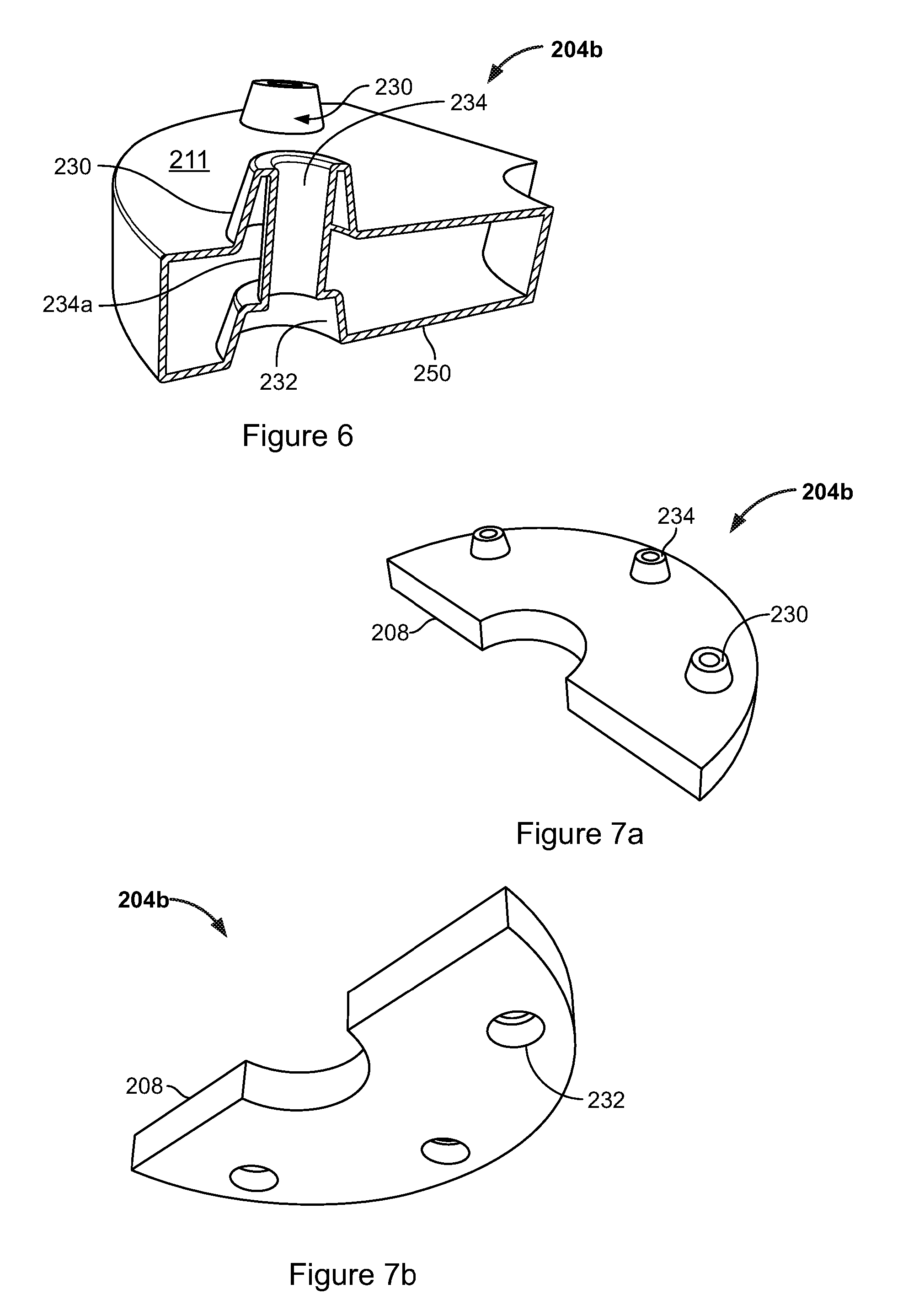
[0016] FIG. 6 represents an individual buoyancy element used in the second buoyancy module, part of which is cut-away to reveal its internal structure;
[0017] FIGS. 7a and 7b represent the same buoyancy element viewed from above and from beneath, respectively;
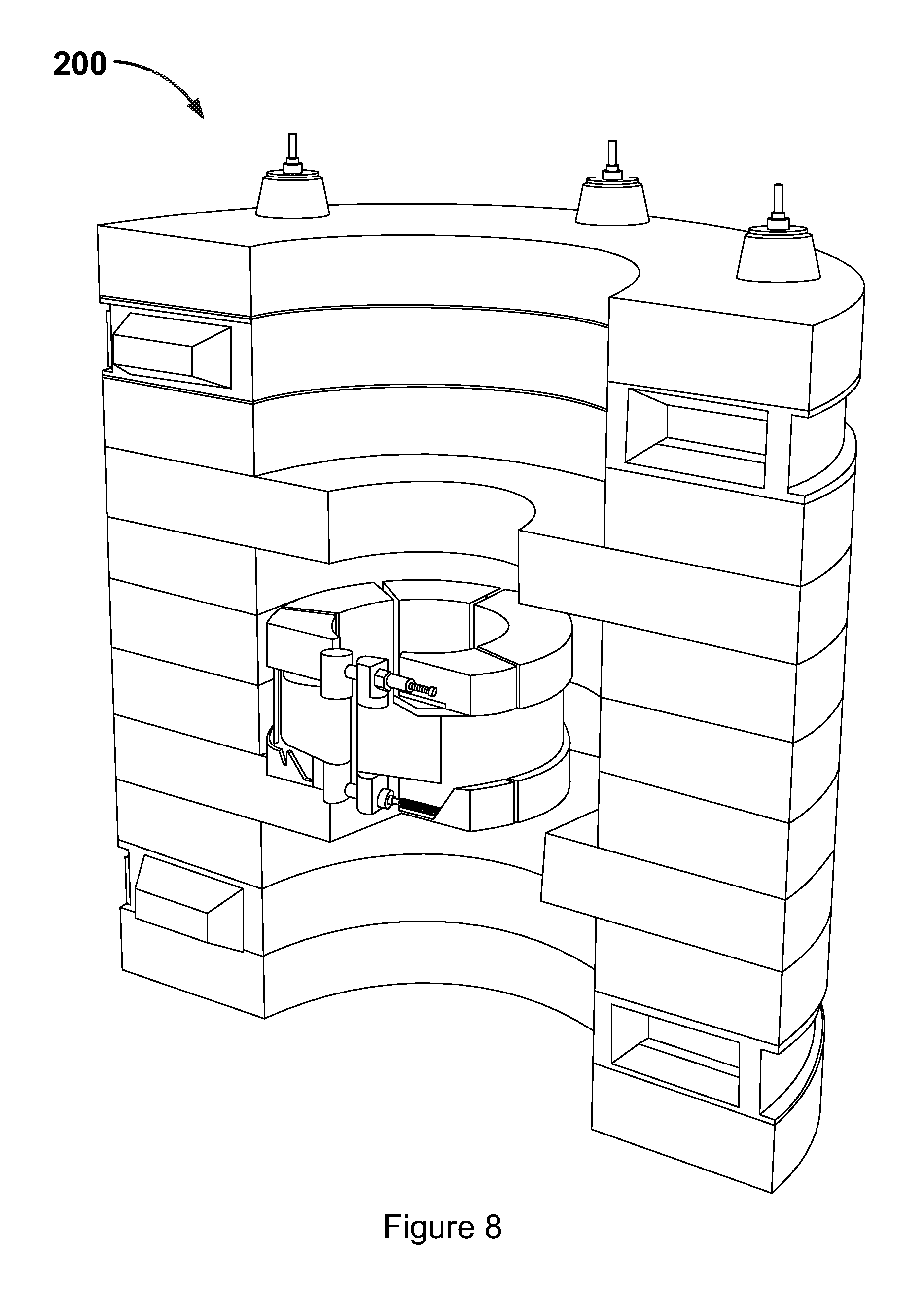
[0018] FIG. 8 is another representation of the second buoyancy module;
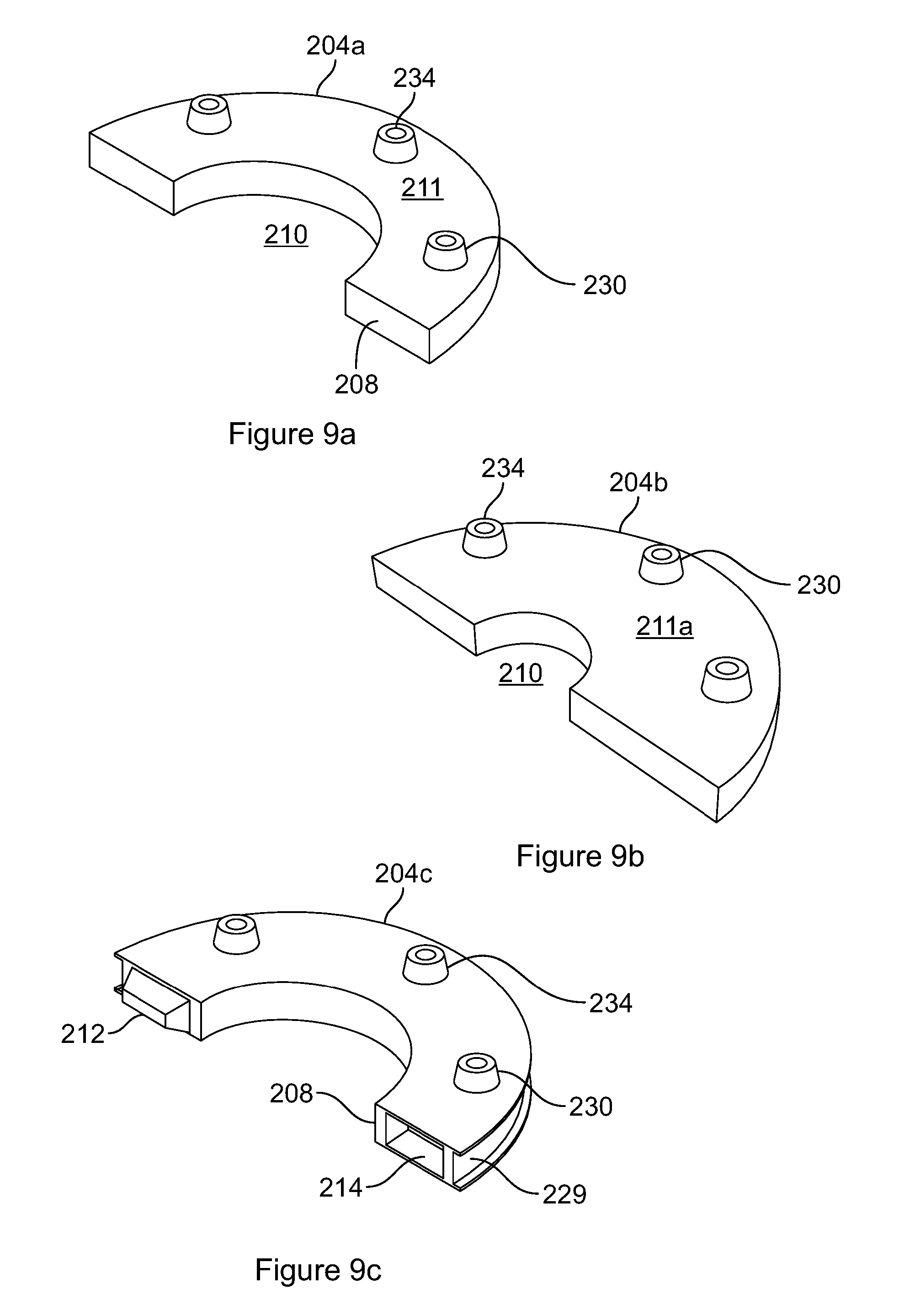
[0019] FIGS. 9a, 9b and 9c each show a respective buoyancy element used in the second buoyancy module;
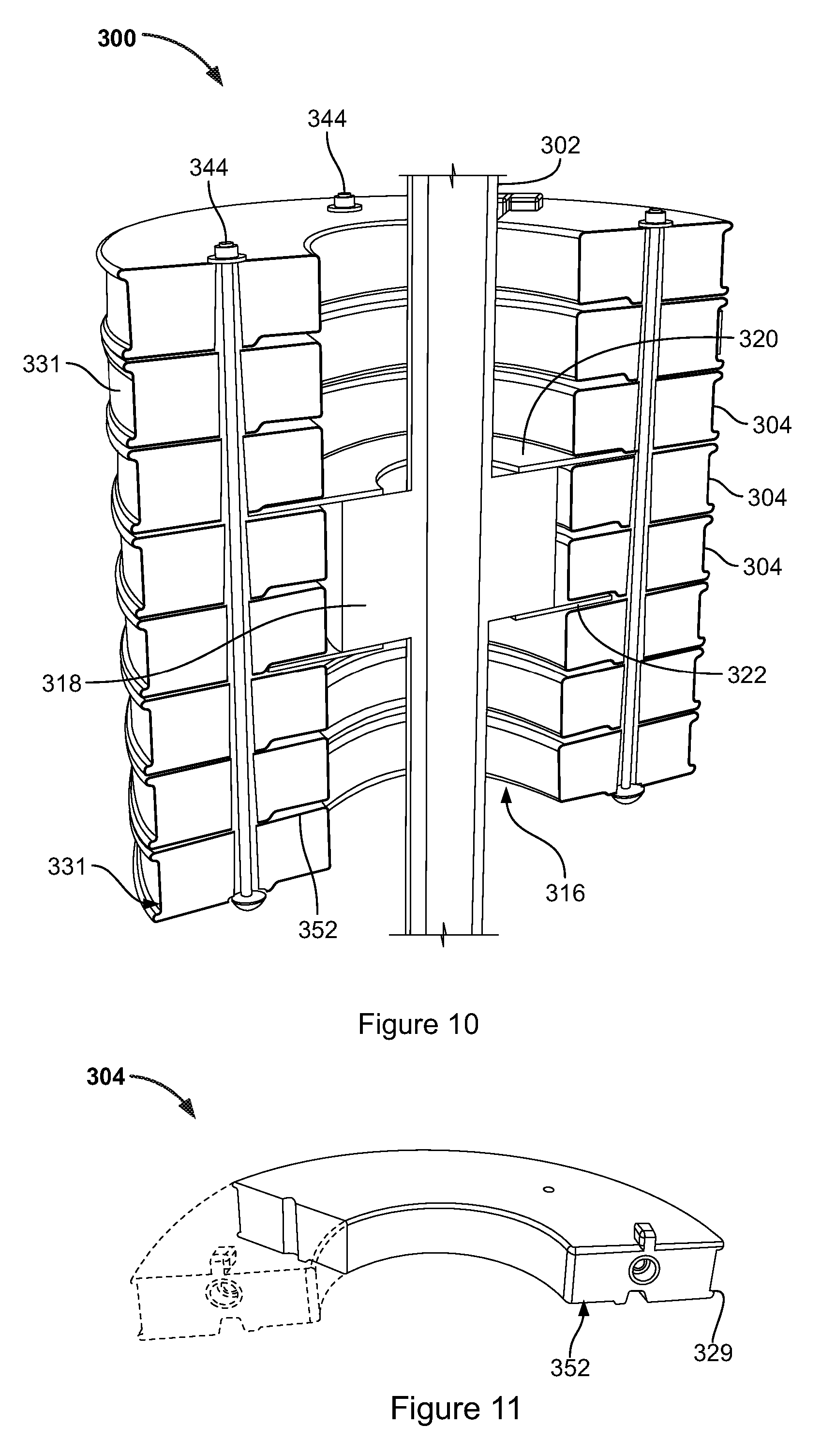
[0020] FIG. 10 represents parts of a third buoyancy module embodying the present invention, some of the module's components being omitted to reveal internal detail;
[0021] FIG. 11 represents a buoyancy element used in the third buoyancy module, partly in phantom;
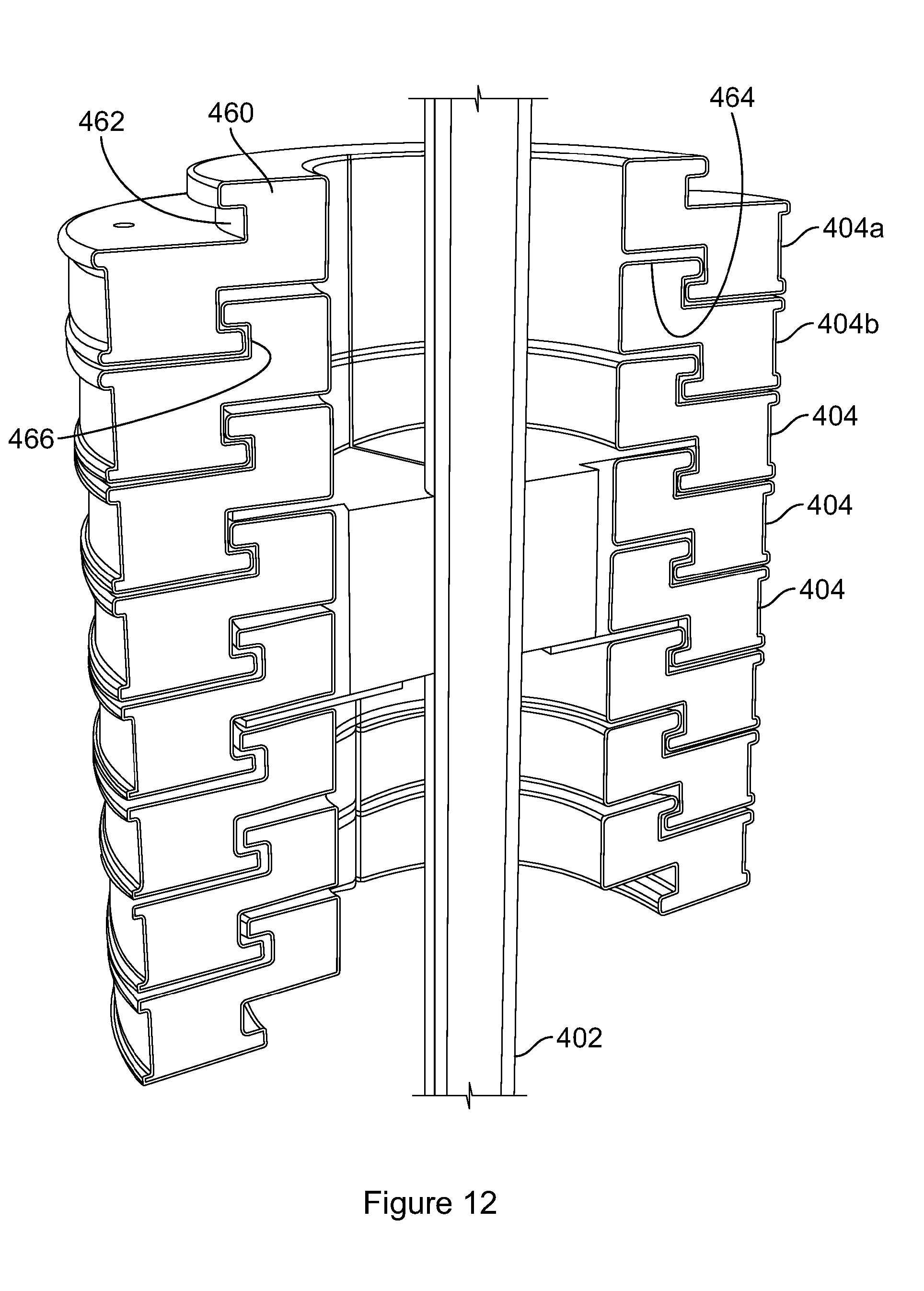
[0022] FIG. 12 represents parts of a fourth buoyancy module embodying the present invention, some of the module's components being omitted to reveal internal detail;
[0023] FIG. 13 represents parts of a fifth buoyancy module embodying the present invention, some of the module's components being omitted to reveal internal detail;
[0024] FIG. 14 represents a further buoyancy element embodying the present invention; and
[0025] FIGS. 15 and 16 represent a sixth buoyancy module embodying the present invention, showing inter alia how the module can be hoisted;
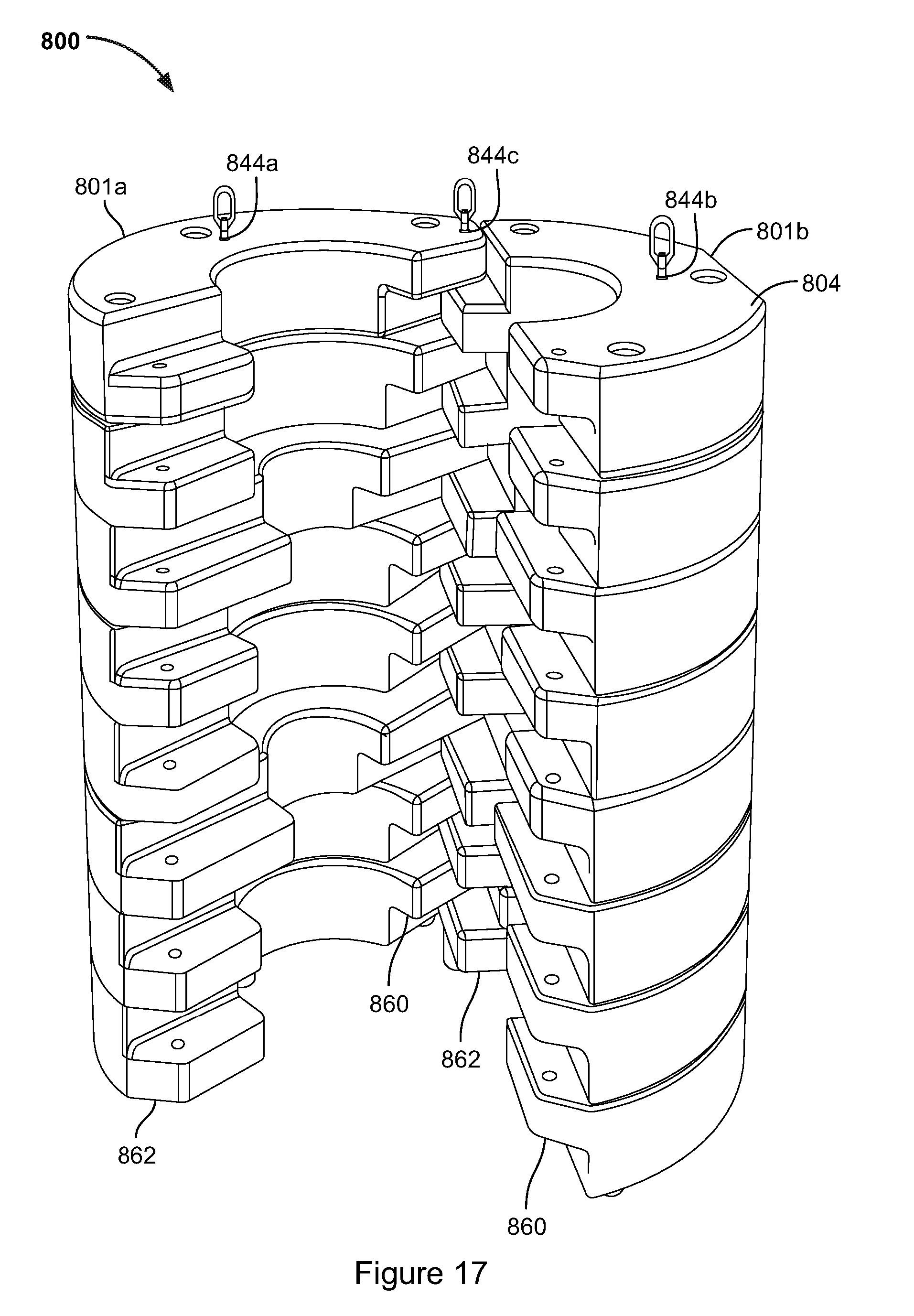
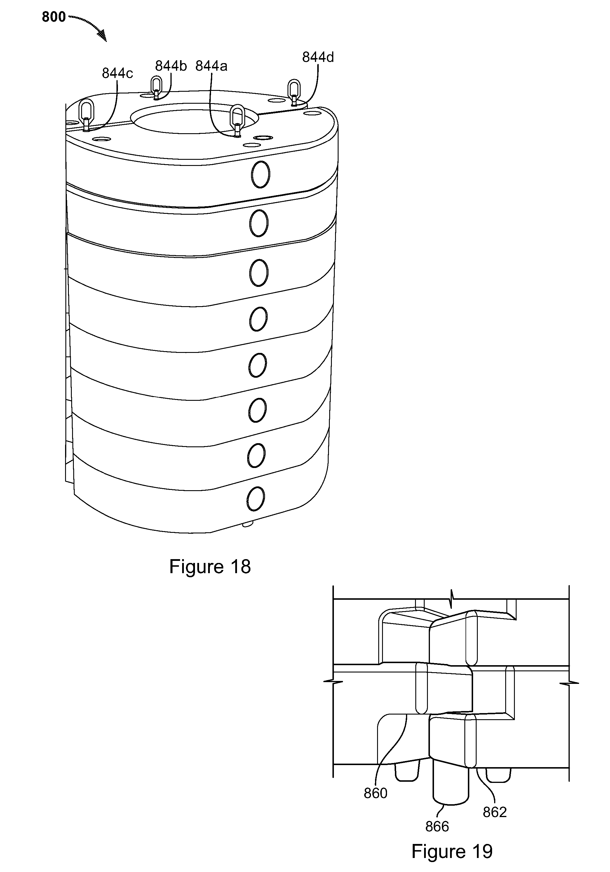
[0026] FIGS. 17 and 18 represent a seventh buoyancy module embodying the present invention, in open and closed configurations respectively;
[0027] FIG. 19 depicts to an enlarged scale a foot arrangement of the seventh buoyancy module;
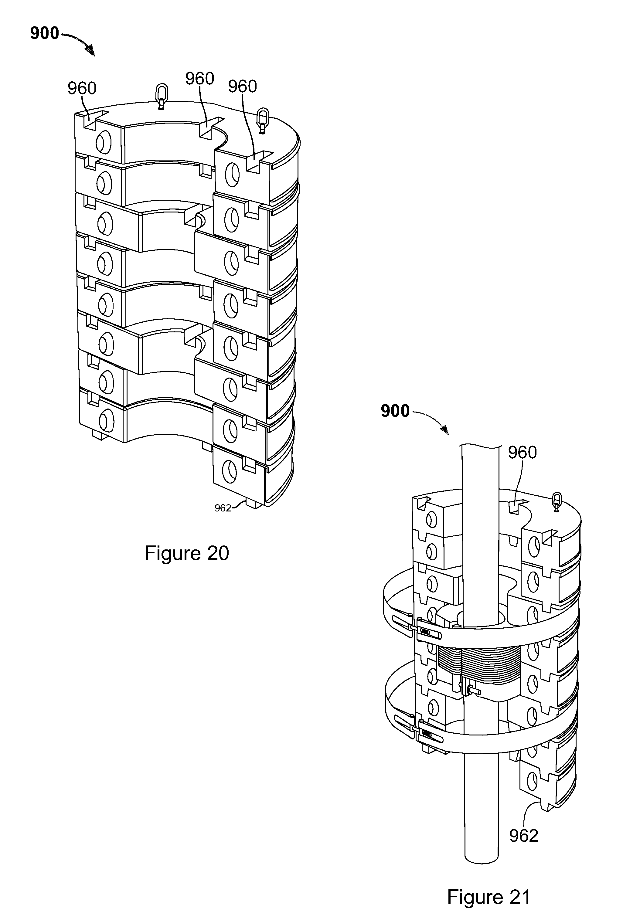
[0028] FIGS. 20 and 21 represent an eighth buoyancy module embodying the present invention; and
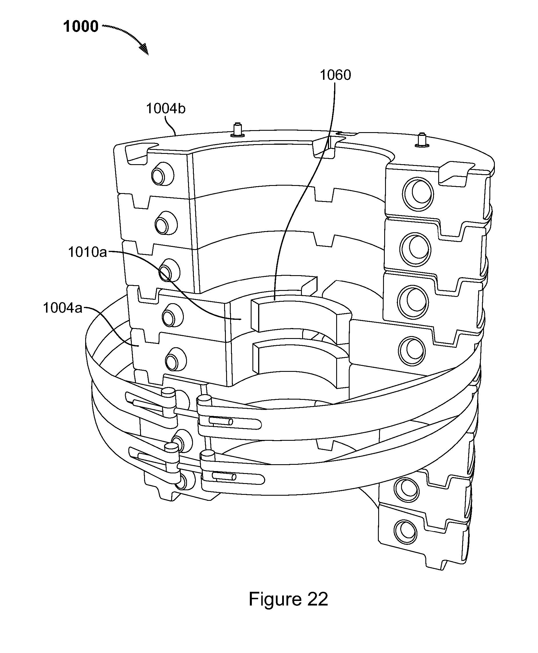
[0029] FIG. 22 represents a ninth buoyancy module embodying the present invention.
[0030] Principles underlying the present invention can be appreciated from a study of FIG. 2 which represents a first buoyancy module 100 embodying the present invention, in position upon an elongate member 102 which may be a conduit, cable, pipe, riser, jumper, pipeline, umbilical or other elongate member to be deployed underwater and to be provided with buoyancy. The buoyancy module 100 is assembled from a set of separately formed buoyancy elements 104. Whereas the buoyancy elements making up the prior art buoyancy module of FIG. 1 are bespoke, those of the present invention are standardised in size and shape and able (a) to be assembled into buoyancy modules of differing sizes and (b) to be used on elongate members 102 having a range of diameters.
[0031] Note that throughout the present description and claims, the term "buoyancy module" refers to an entire module which, in accordance with the present invention, is formed from multiple individually formed "buoyancy elements".
[0032] The buoyancy elements 104 are formed in a manner which enables them to be stacked along the axial direction--that is, one is placed upon another to form a stack extending along the direction of the axis 106 of the elongate member 102. In the assembled buoyancy module 100 multiple buoyancy elements 104 are stacked and coupled to one another to form a module of a desired length. The number of layers in the stack thus determines the axial depth of the module and the volume of water it displaces, and thus the buoyant force it provides. In this way modules of a specified size (and in particular, volume) can be assembled from standardised buoyancy elements 104 without needing to design and manufacture bespoke mouldings to meet that specification.
[0033] Each buoyancy element 104 abuts at least two neighbouring buoyancy elements 104, and is coupled to them, in the loose sense that they form a common assembly and are directly or indirectly secured to one another. For example end buoyancy element 104a is coupled to an axially neighbouring buoyancy element 104b and to a laterally neighbouring buoyancy element, which is not seen in FIG. 2 since those elements in the foreground have been omitted to reveal the interior of the assembly.
[0034] The term "axial neighbours" is used herein to refer to a pair of buoyancy elements which form adjoining layers in the stack of buoyancy elements, such as 104a and 104b in FIG. 2. Other similar phrases such as "axially neighbouring" are to be correspondingly construed. The term "lateral neighbours" refers to a pair of buoyancy elements which are at the same level in the stack of buoyancy elements. Again other similar phrases such as "laterally neighbouring" are to be correspondingly construed. FIG. 15 shows a complete buoyancy module 700 and a laterally neighbouring pair of buoyancy elements is designated 704a, 704b.
[0035] Looking again at FIG. 2, laterally neighbouring buoyancy elements 104 together form a loop encircling the elongate member 102, so that the assembled buoyancy module 100 surrounds and is captive upon the elongate member. In the present embodiment this loop is formed by a pair of buoyancy elements 104, although it is possible that in other embodiments a different number of elements (e.g. three elements, each a 120 degree sector of a circle) may make up the full circumference of the buoyancy module 100. Each buoyancy element 104 has a pair of inner abutment faces 108 between which is a recess 110. Inner abutment faces 108 of laterally neighbouring buoyancy elements 104 abut one another, with their recesses 110 aligned to form a through-going passage for the elongate member 102. In the present embodiment the buoyancy elements are semi-annular in plan, the recesses 110 being semi-circular and the exterior of the assembled buoyancy module being approximately circular in cross section. Other shapes could however be used in other embodiments.
[0036] Each buoyancy element 104 has upper and lower axially directed faces 111, one facing in the opposite direction to the other. In the assembled buoyancy module 100 faces 111 of axially neighbouring buoyancy elements abut one another. The recess 110 extends from one face 111 to the other.
[0037] The buoyancy elements 104 are shaped to provide registration features to provide positive location of the buoyancy element 104 with respect to its neighbours. These are of two types: [0038] a. lateral registration features, which locate the buoyancy element with respect to its lateral neighbour. In the FIG. 2 embodiment these comprise a pip 112 and a recess 114 each formed on the inner abutment face 108. When a pair of laterally neighbouring buoyancy elements is assembled around the elongate member 106, the pip of one is received in the recess of the other and vice-versa. [0039] b. axial registration features, which locate the buoyancy element 104 with respect to its axial neighbours in the stack. These are omitted from FIG. 2, which is somewhat simplified, but examples will be described below in relation to other embodiments.
[0040] The buoyancy elements 104 together form a passage 116 which is open-ended, extending from the exposed face 111 at one end of the buoyancy module 100 to a further exposed face at its other end. This passage 116 is in the present embodiment not flared, as in the prior art buoyancy module. Instead it is of constant diameter, and to accommodate flexure of the elongate member 102 it is oversized with respect to it. That is, the inner diameter of passage 116 is larger than the exterior diameter of the elongate member 102. This does result in some loss of module volume, as compared with the prior art buoyancy module 10 of FIG. 1, where clearance was provided mainly in the flared end regions of the passage. But simple geometric calculations show this to be a small loss of displacement volume, acceptable in typical applications.
[0041] The buoyancy module 100 is located against movement along the elongate member 106 by means of a clamp 118 mounted on the elongate member. The clamp is depicted only schematically in FIG. 2. Suitable clamps are known in the art. Details of some suitable clamps are provided in prior art document PCT/GB2013/051311. The clamp 118 is disposed within the passage 116 of the buoyancy module 100. Since the passage 116 is over-sized and of constant cross section, some additional means needs to be provided for the clamp 118 to engage with the buoyancy module 100. In the present embodiment, first and second locating plates 120, 122 are provided on either side of the clamp 118. First locating plate 120 is sandwiched between an axially neighbouring pair of buoyancy elements 104 above the clamp 118. It has a through-going opening 124 which receives the elongate member 102. Some provision needs to be made for the elongate member 102 to be introduced into the opening 124. This may be achieved by forming the locating plate 120 in two halves (which in the present embodiment are semi-annular) for assembly around the elongate member. The opening 124 is large enough to receive the elongate member 102 but small enough to ensure that the clamp 118 is unable to pass through. The second locating plate 122 is similarly formed to the first but disposed beneath the clamp 118. Together the two locating plates 120, 122 prevent movement of the buoyancy module 100 in either direction along the elongate member 102. The diameter of the openings 124 in the locating plates 120, 122 needs to be matched to some degree to that of the riser, and the plates may need to be tailored to a particular project in this respect, but this is a straightforward process, e.g. involving machining the openings, and need not add greatly to cost or delivery lead time.
[0042] The FIG. 2 embodiment uses only one type of buoyancy element 104 and can thus be manufactured using just one mould. The embodiment depicted in FIGS. 3 to 9 is different in this respect--it uses three different types of buoyancy element 204a, 204b and 204c--but as before the buoyancy elements are stacked to form a buoyancy module 200 of a desired axial depth, and laterally neighbouring buoyancy elements together encircle the elongate member (which is not shown in these drawings), forming a passage 216 through which the elongate member passes. A clamp 218 is secured upon the elongate member to axially locate the buoyancy module 200, and FIG. 3 gives a little more detail of a suitable clamp, seen to comprise multiple part-annular clamp shells 218a surrounded by a clamping band 218b.
[0043] A first type of buoyancy element 204a is depicted on its own in FIG. 9a. It is semi-annular in shape. It has plain inner abutment faces 208 without any lateral registration features, and a semi-circular cut-away or recess 210 to accommodate the elongate member. Male axial registration features 230 (formed as upstanding pips in the present example, although they may take other forms) are provided on a top face 211a of the buoyancy element 204a to register with complementary female axial registration features 232 on the bottom face 211b of an axially neighbouring buoyancy element. The female axial registration features are formed as shallow recesses in the present example, and are seen in FIGS. 5b, 6 and 7b. The male and female axial registration features 230, 232 locate one buoyancy element with respect to its axial neighbour in the stack.
[0044] A second type of buoyancy element 204b is depicted on its own in FIG. 9b and in FIGS. 7a and 7b and differs from the first type only in that the radius of the semi-circular cut-away 210 is smaller. The buoyancy elements of the second type 204b are disposed on either side of the clamp 218 and their faces 211a, 211b (see FIG. 3) abut the clamp and are unable to pass it, whereby these buoyancy elements serve to axially locate the buoyancy module 200 with respect to the clamp 218.
[0045] A third type of buoyancy element 204c is depicted on its own in FIG. 9c and differs from the first type in two respects:-- [0046] it comprises lateral registration features on its inner abutment faces 208. These comprise a tongue 212 for receipt in a recess 214. [0047] it has a circumferentially extending recess 229 in its outer surface, to receive and locate a strap 231 which is secured around the buoyancy module 200 under tension.
[0048] In the illustrated example only two buoyancy elements of the third type 204c are provided and they serve to locate one half of the buoyancy module 200 (i.e. the components seen in FIG. 3) with respect to its other half and, by virtue of the straps 231, to hold the two halves together. More of this third type of buoyancy element 204c could be incorporated in other assemblies.
[0049] The three different types of buoyancy element 204a, b, c may be formed using a single basic mould with removable inserts ("change parts").
[0050] All of the buoyancy elements 204a, b and c are provided with through-going openings 234 extending from one face 211 to the other. In the illustrated example these pass through the axial registration features 230, 232 and there are three of them in each buoyancy element 204a, b, c. In the assembled buoyancy module 200 they align to form through-going coupling passages 238 extending from one end face 211a of the buoyancy module to the other end face 211b (see FIG. 4 in particular).
[0051] The buoyancy elements 204 are coupled to one another to form the buoyancy module 200. Prior to deployment, a pair of half shells is assembled. FIG. 3 depicts a single half shell. Respective elongate threaded coupling members 244 are passed through each of the coupling passages 238 to secure together the stacked buoyancy elements 204a, b, c forming the half shell. In FIG. 5a, a washer 246 is seen to bear upon the top-most element in the stack and to be retained by a nut 249 on the coupling member 244, and in FIG. 5b a further washer 248 bears upon the bottom-most element in the stack and is likewise retained by a nut on the coupling member 244.
[0052] Mounting the buoyancy module 200 to the elongate member involves assembling two half shells to one another around the elongate member. The aforementioned straps 231 secure the two half shells together.
[0053] The internal structure of the buoyancy elements 204a, b, c can best be seen in FIG. 6. The buoyancy elements can be manufactured by first forming an external plastics shell 250 which forms the outer surface of the buoyancy element and has a small wall thickness. This can be done by rotomoulding of plastics material. Other moulding processes may be used. In the present embodiment the shell 250 comprises polyethylene, although other mouldable materials may be used. The shell 250 is then filled with settable plastics material, which is syntactic foam in the present embodiment and which forms a structural core for the buoyancy element. The shell acts as mould for the core.
[0054] The through-going openings 234 are formed, as seen in FIGS. 4, 5 and 6, by opening walls 234a which are integral with the remainder of the shell 250 and are formed during its rotomoulding.
[0055] Note that because the required depth of the entire buoyancy module 200 is made up from multiple buoyancy elements 204a, b, c which are stacked along the axial direction, the depth of individual buoyancy elements 204 in the present embodiment is much smaller than the depth of the prior art buoyancy modules 12, 14 depicted in FIG. 1. The large mouldings forming the prior art buoyancy modules had to be filled with syntactic in multiple pours, each being allowed to set before the next, to prevent them from being destroyed by the heat that would be released upon curing were they to be filled in one process. This problem is greatly alleviated by the present invention due to the smaller depth of the buoyancy modules, which can as a result be filled either in one pour, or at least in a greatly reduced number of pours. This reduces labour and especially reduces the time taken for manufacture of each buoyancy element. It may also be unnecessary to support the shell 250 in a jig during pouring of the core. If a jig is required, it can be a standard item used for multiple orders, as opposed to a bespoke or adaptable jig used in relation the prior art modules of FIG. 1.
[0056] FIGS. 10 and 11 represent still a further buoyancy module 300 embodying the present invention. This uses buoyancy elements 304 of only a single type. That is, all the buoyancy elements 304 have the same shape and can be formed in the same mould. As before the buoyancy elements 304 are stacked to form a buoyancy module 300 of a desired axial depth, and laterally neighbouring buoyancy elements together encircle the elongate member 302, forming a passage 316 through which the elongate member passes. A clamp 318 is secured upon the elongate member 302 to axially locate the buoyancy module 300.
[0057] In this embodiment each of the buoyancy elements 304 is has a circumferentially extending recess 329 in its outer surface, able to receive and locate a strap 331 which secured around the buoyancy module 300 under tension to maintain its two halves together. Note that only two straps 331 are used in this embodiment, however.
[0058] Like the embodiment depicted in FIGS. 3 to 9, the present embodiment uses threaded, axially extending coupling members 344 to secure the stacked buoyancy elements 304 to one another.
[0059] Like the embodiment depicted in FIG. 2, the present embodiment has locating plates 320, 322 on either side of the clamp 318 to axially locate the buoyancy module 300, the locating plates 320, 322 being sandwiched between axially neighbouring buoyancy elements 304. However in the present embodiment the locating plates 320, 322 are smaller in diameter than the buoyancy elements 304 and are received in shallow annular recesses 352 formed in the lower face of each buoyancy element 304.
[0060] FIG. 12 represents yet a further buoyancy module 400 which differs from the embodiment depicted in FIGS. 10 and 11 in that the threaded members 344 are dispensed with. Instead axially neighbouring buoyancy elements 404 are shaped to interlock and so couple to one another in a manner which prevents one from being axially withdrawn from the other. This is achieved in the illustrated example by providing each buoyancy element 404 with, on one face, a semi-annular boss 460 with a radial undercut 462 running around its circumference, and on its other face with a semi-annular recess 464 to with a radially inwardly directed circumferential tongue 466 running around its circumference. In the assembled buoyancy module 400 the boss 460 of one buoyancy element 404 is received in the recess 464 of its axial neighbour, and is locked in that position by engagement of the tongue 466 in the undercut 462. The top-most lateral pair of buoyancy elements, one of which is designated 404a in the drawing and the other of which is omitted, are secured to one another by strap 331. Note that this may be sufficient in itself to prevent disassembly of the buoyancy module 400. The top-most pair of buoyancy elements embraces the second pair 404b below them and prevents them from being laterally separated. The second pair 404b of buoyancy elements embraces the third pair 404c below them and so prevents them from being separated, and so on. In practice, bands at certain intervals may be needed to provide a sufficiently robust assembly.
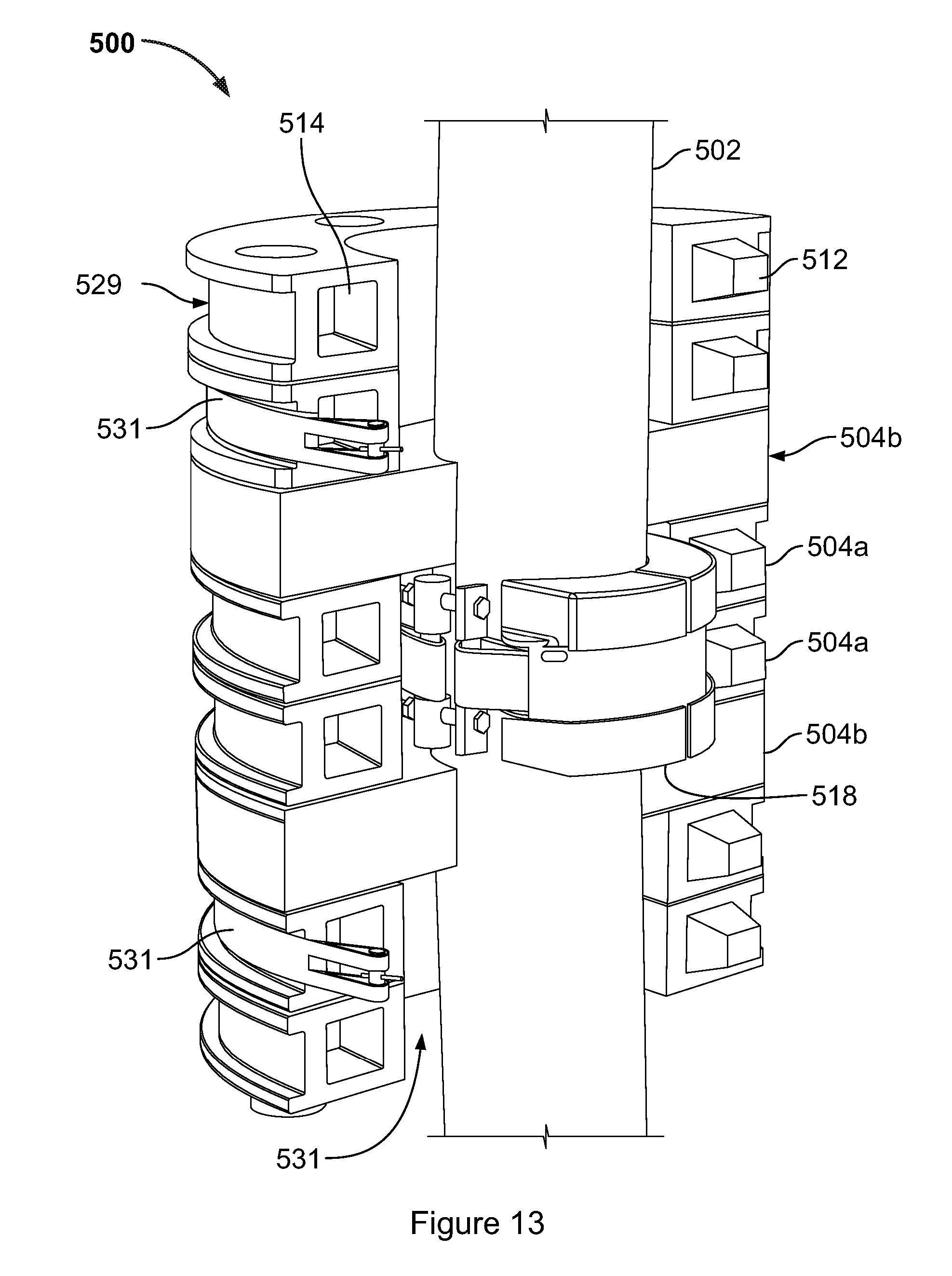
[0061] FIG. 13 represents yet a further buoyancy module 500 embodying the present invention. As before buoyancy elements 504 are stacked to form a buoyancy module 500 of a desired axial depth, and laterally neighbouring buoyancy elements together encircle the elongate member 502, forming a passage 516 through which elongate member 502 passes. A clamp 518 is secured upon the elongate member 502 to axially locate the buoyancy module 500.
[0062] This embodiment uses two different types of buoyancy element.
[0063] A first type 504a of buoyancy element has a circumferential recess 529 to receive and locate a strap 531, and also has male and female lateral registration features formed by a square upstand 512 and a square recess 514.
[0064] A second type 504b of buoyancy element serves to engage the clamp 518, and is in this embodiment a moulded, buoyant item which can have the shell-and-core structure described above.
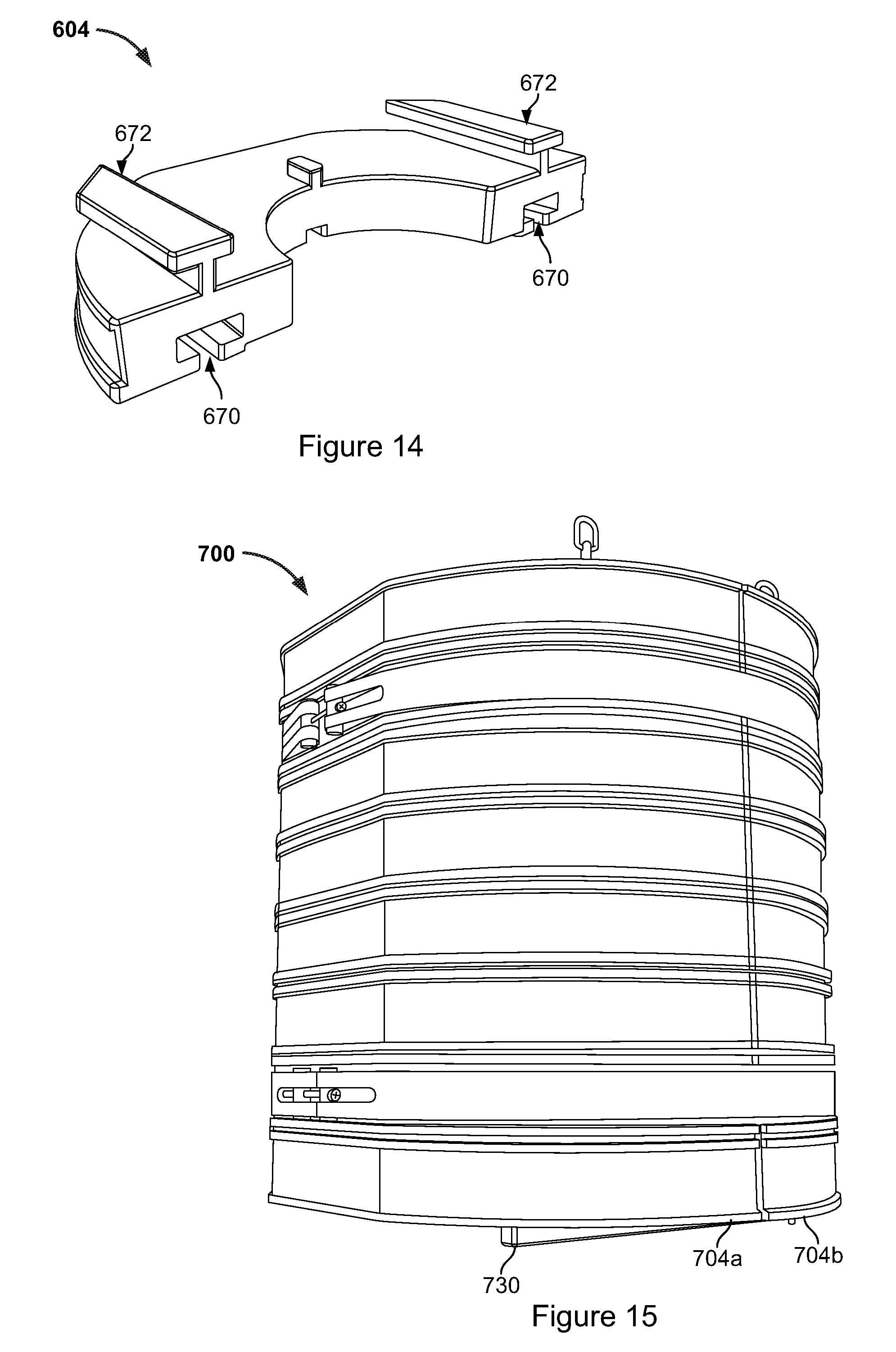
[0065] FIG. 14 represents a buoyancy element 604 according to still another embodiment of the present invention, which exemplifies a different manner in which the buoyancy elements 604 can be shaped to interlock and so couple to their axial neighbours. Here, the lower face of the buoyancy element 604 has a pair of elongate "T" section slots 670 and its upper face carries a complementary pair of "T" section upstands 672. The upstands 672 of one buoyancy element 604 are to be slid into the slots 670 of its axial neighbour, whereupon the engagement of the upstands with the slots prevents one from being withdrawn from the other along the axial direction.
[0066] There are numerous other ways in which the buoyancy elements can be coupled to one another. For example, the buoyancy elements forming one layer may be shaped to engage with the next in the manner of a part-turn lock. Alternatively elements of successive layers may be angularly offset so that the elements of one half form a set of fingers interleaved with matching fingers of the other half. By passing threaded coupling members axially through these interlocked fingers the two halves can be secured together without need of straps.
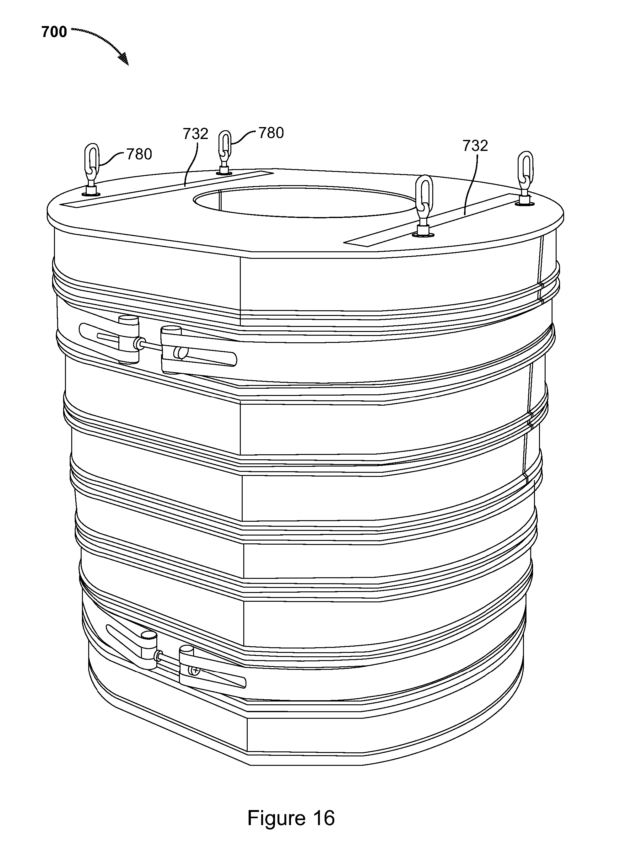
[0067] FIGS. 15 and 16 show an entire buoyancy module 700 embodying the present invention.
[0068] This differs from the above described embodiments with respect to the axial registration features, which in this embodiment comprise elongate skids 730 for receipt in slots 732. These perform a dual function. As well as locating one layer of buoyancy elements relative to its axial neighbour, the skids 730 on the lower surface of the module 700 provide the surfaces through which the module 700 rests upon the ground prior to its deployment. They can easily be incorporated in the moulded shells of the buoyancy elements 704 during its moulding and so add nothing to cost. And by keeping the remainder of the shell from contact with the ground which might abrade it, they make it possible to dispense with other protective measures such as the additional wooden skids currently used to protect the module during handling. The skids 730 can be sacrificial, in the sense that they can be abraded during handling and that this does not impair the module's function once it is installed. The same dual function may be performed by other types of upstand upon the buoyancy elements' lower faces.
[0069] For handling purposes hooks eyes 780 may be screwed on to the threaded members used to secure the stacked buoyancy elements 704 together.
[0070] FIGS. 17 to 19 show a further embodiment of the invention in the form of a buoyancy module 800 in which buoyancy elements 804 form two half shells 801a, 801b, one hinged to the other. This makes mounting of the module on the elongate member straightforward. The buoyancy module 800 is initially open as depicted in FIG. 17, enabling the elongate member to be introduced to it. Turning one half shell relative to the other about the hinge then closes it (FIG. 18). In the illustrated embodiment the buoyancy elements 804 each have a pair of fingers 860, 862, one at each end of the element. The fingers 860, 862 each have through-going openings extending along the axial direction. Each half shell 801a, 801b comprises a stack of buoyancy elements 804 coupled together by a respective elongate threaded coupling member 844a, 844b. To form the hinge, the fingers 860 of one half shell 801a are overlapped and interleaved with the fingers 862 of the other half shell 801b, so that the fingers' through-going openings are aligned to receive a further elongate threaded coupling member 844a, about which the half shells turn. When the buoyancy module 800 is closed as in FIG. 18, the fingers 862 of the first half shell 801a overlap and are interleaved with the fingers 801b of the second half shell 801b, and are secured to one another by passing still a further threaded coupling member 844d through their aligned openings, to lock the module in its closed configuration. The straps used in other versions can be dispensed with. Note that while the present embodiment used shaped fingers, an alternative would be to angularly offset each buoyancy element 804 with respect to its neighbours, enabling ends of each element of one half shell to be interleaved with the ends of the elements of the other half shell.
[0071] In the present embodiment the coupling members 844 terminate in respective feet 866 (see FIG. 19) on which the buoyancy module 800 is able to stand prior to its deployment. Abrasion damage to the module itself through contact e.g. with the deck of a ship may thus be avoided.
[0072] FIGS. 20 and 21 depict still a further buoyancy module 900 embodying the present invention. In this example the axial registration features comprise slots 960 on one face of buoyancy elements 904 and tongues 962 on the opposite face, the tongues of one buoyancy element being receivable in the slots of another.
[0073] FIG. 22 depicts still a further buoyancy module 1000 embodying the present invention. Whereas the modules described so far rely on a separately formed clamp to resist movement of the module along the elongate member on which it is mounted, buoyancy module 1000 is formed in such a manner that it is able to locate itself against such movement. It may be regarded as having an integral clamp. For this purpose some of its buoyancy elements 1004a have recesses 1010a whose internal diameter is smaller than that of the remaining buoyancy elements 1004b. These recesses 1010a carry on their radially inwardly directed faces respective resilient shoes 1060 through which seat in use upon the elongate member. The shoes 1060 may comprise an elastomer. Rubber is suitable. The shoes 1060 are somewhat elastically deformed when seated on the elongate member, providing a clamping force. Due to their resilience they are able to maintain this clamping force despite factors such as creep which might otherwise enable the integral clamp to loosen over time. To resist creep, the syntactic foam of the clamp buoyancy elements 1004a may be a denser, stiffer material than that of the remaining elements 1004b. Straps 1031 are applied around the clamp buoyancy elements 1004a to apply the required force directly to them to provide clamping. The drawing shows a module having two pairs of clamp buoyancy elements 1004a, but a different number may be used. This number may be one or three.
[0074] The coupling members 244, 344, 844 used to couple together the buoyancy elements in a stack may take a variety of forms. They may comprise metal rod, e.g. of stainless steel. They may be flexible. They may be formed of a composite, such as a fibre reinforced composite.
[0075] The invention provide various advantages. It makes it possible to use one set of mouldings, which may be manufactured in advance of orders and kept in stock, to make buoyancy modules having a range of different volumes and suitable for use on elongate members having a range of different diameters. The lead time involved in the design and manufacture process described above can thus be avoided. The manufacture of the relatively shallow buoyancy elements of the present invention can be simpler in that fewer pouring processes are required to mould the structural core and jigging may not be necessary. The wall thickness of the shells used in the present embodiment can be relatively small due to the small size of the buoyancy elements, which can reduce rotomoulding time. There is a degree of variability in volume of the moulded buoyancy elements but in accordance with the invention this can be allowed for by matching--in a given buoyancy module--some elements which are over-sized with some that are under-sized, making it possible to closely match a design volume. The relatively small mouldings used in embodiments of the invention can be made in smaller rotomoulding machines, which are more widely available.
* * * * *
D00000
D00001
D00002
D00003
D00004
D00005
D00006
D00007
D00008
D00009
D00010
D00011
D00012
D00013
D00014
D00015
XML
uspto.report is an independent third-party trademark research tool that is not affiliated, endorsed, or sponsored by the United States Patent and Trademark Office (USPTO) or any other governmental organization. The information provided by uspto.report is based on publicly available data at the time of writing and is intended for informational purposes only.
While we strive to provide accurate and up-to-date information, we do not guarantee the accuracy, completeness, reliability, or suitability of the information displayed on this site. The use of this site is at your own risk. Any reliance you place on such information is therefore strictly at your own risk.
All official trademark data, including owner information, should be verified by visiting the official USPTO website at www.uspto.gov. This site is not intended to replace professional legal advice and should not be used as a substitute for consulting with a legal professional who is knowledgeable about trademark law.