Apparatus And Methods For Additively Manufacturing Adhesive Inlet And Outlet Ports
Martinez, JR.; Antonio Bernerd ; et al.
U.S. patent application number 15/959036 was filed with the patent office on 2019-10-24 for apparatus and methods for additively manufacturing adhesive inlet and outlet ports. The applicant listed for this patent is Divergent Technologies, Inc.. Invention is credited to William David Kreig, Antonio Bernerd Martinez, JR., Chukwubuikem Marcel Okoli, Roy Smith, David Brian TenHOUTEN, Muhammad Faizan Zafar.
| Application Number | 20190322040 15/959036 |
| Document ID | / |
| Family ID | 68237346 |
| Filed Date | 2019-10-24 |


View All Diagrams
| United States Patent Application | 20190322040 |
| Kind Code | A1 |
| Martinez, JR.; Antonio Bernerd ; et al. | October 24, 2019 |
APPARATUS AND METHODS FOR ADDITIVELY MANUFACTURING ADHESIVE INLET AND OUTLET PORTS
Abstract
Apparatus and methods for additively manufacturing adhesive inlet and outlet ports are presented herein. Adhesive inlet and outlet ports are additively manufactured to include additively manufactured (AM) valves for reducing and/or eliminating sealant leakage and backflow. Robot end effectors are tailored to interface with the AM inlet and outlet ports and to provide an adhesive source and/or a vacuum source. AM inlet and outlet ports enable robust, lightweight, multi-material AM parts connected via adhesive joining.
| Inventors: | Martinez, JR.; Antonio Bernerd; (El Segundo, CA) ; Zafar; Muhammad Faizan; (Long Beach, CA) ; Okoli; Chukwubuikem Marcel; (Los Angeles, CA) ; Kreig; William David; (Huntington Beach, CA) ; Smith; Roy; (Escondido, CA) ; TenHOUTEN; David Brian; (Los Angeles, CA) | ||||||||||
| Applicant: |
|
||||||||||
|---|---|---|---|---|---|---|---|---|---|---|---|
| Family ID: | 68237346 | ||||||||||
| Appl. No.: | 15/959036 | ||||||||||
| Filed: | April 20, 2018 |
| Current U.S. Class: | 1/1 |
| Current CPC Class: | B33Y 30/00 20141201; B29C 64/106 20170801; B29C 64/379 20170801; B33Y 10/00 20141201; B29C 64/209 20170801; B33Y 80/00 20141201 |
| International Class: | B29C 64/209 20060101 B29C064/209; B29C 64/379 20060101 B29C064/379; B29C 64/106 20060101 B29C064/106 |
Claims
1. An apparatus comprising: an additively manufactured (AM) inlet port configured to receive an adhesive; and an AM outlet port comprising an AM outlet adhesive valve configured to impede an adhesive outflow at the AM outlet port.
2. The apparatus of claim 1, wherein the adhesive flow is unidirectional from the AM inlet port to the AM outlet port.
3. The apparatus of claim 1, wherein the AM outlet adhesive valve comprises a lattice configured to impede the adhesive outflow at the AM outlet port.
4. The apparatus of claim 1, wherein the AM outlet port is configured to receive a vacuum; and wherein the AM outlet adhesive valve is configured to facilitate the adhesive flow from the AM inlet port to the AM outlet port by engaging the vacuum.
5. The apparatus of claim 4, wherein the AM outlet adhesive valve comprises a lattice configured to: engage the vacuum by passing air; and impede the adhesive outflow at the AM outlet port.
6. The apparatus of claim 5, wherein the AM outlet adhesive valve comprises a plurality of outlet spring loaded tangs configured to: couple with a vacuum effector; facilitate the vacuum when coupled with the vacuum effector; and impede the adhesive outflow at the AM outlet port when decoupled from the vacuum effector.
7. The apparatus of claim 4, wherein the AM outlet adhesive valve comprises: a gap region; and an AM ball configured to facilitate the vacuum by passing air through the gap region, and impede the adhesive outflow at the AM outlet port by blocking the gap region when the adhesive reaches the gap region.
8. The apparatus of claim 7, wherein the AM outlet adhesive valve further comprises a spring positioned to provide support to the AM ball.
9. The apparatus of claim 4, wherein the AM outlet adhesive valve comprises a flap configured to: facilitate the vacuum by passing air; and impede the adhesive outflow at the AM outlet port by blocking the outlet port when the adhesive reaches the outlet port.
10. The apparatus of claim 9, wherein the flap is configured to lock into place upon completion of an adhesive fill within the apparatus.
11. The apparatus of claim 1, wherein the AM inlet port comprises an AM inlet adhesive valve configured to: facilitate the adhesive flow from the AM inlet port to the AM outlet port; and impede an adhesive outflow at the AM inlet port.
12. The apparatus of claim 1, wherein the AM outlet adhesive valve comprises a pop-in element configured to receive a pressure spike when adhesive reaches the pop-in element to indicate that a corresponding adhesive channel is approximately full.
13. The apparatus of claim 12, wherein the AM inlet adhesive valve comprises a lattice configured to impede the adhesive outflow at the AM inlet port.
14. The apparatus of claim 12, wherein the AM inlet adhesive valve comprises a plurality of inlet spring loaded tangs configured to: couple with an adhesive effector; facilitate the adhesive flow from the AM inlet port to the AM outlet port when coupled with the adhesive effector; and impede the adhesive outflow at the AM inlet port when decoupled from the adhesive effector.
15. The apparatus of claim 12, wherein the AM inlet adhesive valve comprises a flap configured to: facilitate the adhesive flow from the AM inlet port to the AM outlet port when the adhesive is applied at the inlet port; and impede the adhesive outflow at the AM inlet port by blocking the inlet port when the adhesive is removed from the inlet port.
16. The apparatus of claim 15, wherein the flap is configured to lock into place upon completion of an adhesive fill within the apparatus.
17. An apparatus comprising an AM effector for applying adhesive to an AM adhesive port, the AM effector comprising: a first channel supporting a seal plug; and a second channel coupled to the first channel and configured to provide an adhesive to the AM adhesive port.
18. The apparatus of claim 17, wherein the AM adhesive port comprises an AM plug acceptor co-printed with the AM effector.
19. A method of manufacturing an AM node, the method comprising: additively manufacturing an AM inlet port configured to receive an adhesive; and additively manufacturing an AM outlet port to comprise an AM outlet adhesive valve configured to facilitate an adhesive flow from the AM inlet port to the AM outlet port and to impede an adhesive outflow at the AM outlet port.
20. The method of claim 19, wherein the adhesive flow is unidirectional from the AM inlet port to the AM outlet port.
21. The method of claim 19, wherein additively manufacturing the AM outlet port to comprise an AM outlet adhesive valve further comprises: additively manufacturing a lattice within the AM outlet adhesive valve, the lattice configured to impede the adhesive outflow at the AM outlet port.
22. The method of claim 19, wherein the AM outlet port is configured to receive a vacuum; and wherein the AM outlet adhesive valve is configured to facilitate the unidirectional adhesive flow from the AM inlet port to the AM outlet port by facilitating the vacuum.
23. The method of claim 22, wherein additively manufacturing the AM outlet port to comprise an AM outlet adhesive valve comprises: additively manufacturing a lattice within the AM outlet adhesive valve, the lattice configured to facilitate the vacuum by passing air and to impede the adhesive outflow at the AM outlet port.
24. The method of claim 22, wherein additively manufacturing the AM outlet port to comprise an AM outlet adhesive valve comprises: additively manufacturing a plurality of outlet spring loaded tangs configured to couple with a vacuum effector, to facilitate the vacuum when coupled with the vacuum effector, and to impede the adhesive outflow at the AM outlet port when decoupled from the vacuum effector.
25. The method of claim 22, wherein additively manufacturing the AM outlet port to comprise an AM outlet adhesive valve comprises: additively manufacturing a gap region; and additively manufacturing an AM ball configured to facilitate the vacuum by passing air through the gap region and to impede the adhesive outflow at the AM outlet port by blocking the gap region when the adhesive reaches the gap region.
26. The method of claim 25, wherein additively manufacturing the AM outlet port to comprise an AM outlet adhesive valve further comprises: additively manufacturing a spring positioned to provide support to the AM ball.
27. The method of claim 22, wherein additively manufacturing the AM outlet port to comprise an AM outlet adhesive valve comprises: additively manufacturing a flap configured to facilitate the vacuum by passing air and to impede the adhesive outflow at the AM outlet port by blocking the outlet port when the adhesive reaches the outlet port.
28. The method of claim 27, wherein the flap is configured to lock into place upon completion of an adhesive fill.
29. The method of claim 22, wherein additively manufacturing the AM inlet port configured to receive an adhesive comprises: additively manufacturing the inlet port to comprise an AM inlet adhesive valve configured to facilitate the unidirectional adhesive flow from the AM inlet port to the AM outlet port and to impede an adhesive outflow at the AM inlet port.
30. The method of claim 29, wherein additively manufacturing the AM inlet port to comprise an AM inlet adhesive valve comprises: additively manufacturing a lattice within the AM inlet adhesive valve, the lattice configured to facilitate the unidirectional adhesive flow from the AM inlet port to the AM outlet port and to impede an adhesive outflow at the AM inlet port.
31. The method of claim 29, wherein additively manufacturing the AM inlet port to comprise an AM inlet adhesive valve comprises: additively manufacturing a plurality of inlet spring loaded tangs configured to couple with an adhesive effector, to facilitate the unidirectional adhesive flow from the AM inlet port to the AM outlet port when coupled with the adhesive effector, and to impede the adhesive outflow at the AM inlet port when decoupled from the adhesive effector.
32. The method of claim 29, wherein additively manufacturing the AM inlet port to comprise an AM inlet adhesive valve comprises: additively manufacturing a flap configured to facilitate the unidirectional adhesive flow from the AM inlet port to the AM outlet port when the adhesive is applied at the inlet port and to impede the adhesive outflow at the AM inlet port by blocking the inlet port when the adhesive is removed from the inlet port.
33. The method of claim 32, wherein the flap is configured to lock into place upon completion of an adhesive fill.
34. A method of applying an adhesive to an apparatus comprising an AM inlet port and an AM outlet port, the method comprising: providing an adhesive at the AM inlet port; facilitating an adhesive flow from the AM inlet port to the AM outlet port using an AM valve; and terminating the adhesive flow.
35. The method of claim 34, wherein the AM outlet port comprises the AM valve and the method further comprises: impeding an adhesive outflow at the AM outlet port.
36. The method of claim 35, wherein the AM valve comprises a lattice; wherein facilitating an adhesive flow from the AM inlet port to the AM outlet port using the AM valve comprises: providing a vacuum at the AM outlet port; and orienting the lattice to facilitate the adhesive flow from the AM inlet port to the AM outlet port using the AM valve; and wherein terminating the adhesive flow comprises: measuring a pressure increase indicative of the adhesive reaching the lattice; and terminating the adhesive flow in response to the pressure increase.
37. The method of claim 35, wherein the AM valve comprises a plurality of spring loaded AM tangs; wherein facilitating an adhesive flow from the AM inlet port to the AM outlet port using the AM valve comprises: coupling a vacuum effector with the plurality of spring loaded AM tangs; and drawing a vacuum with the vacuum effector; and wherein terminating the adhesive flow comprises: removing the vacuum effector when the adhesive reaches the AM outlet port.
38. The method of claim 35, wherein the AM valve comprises an AM gap region and an AM ball; wherein facilitating an adhesive flow from the AM inlet port to the AM outlet port using the AM valve comprises: passing air through the gap region; and wherein terminating the adhesive flow comprises: blocking the gap region when the adhesive reaches the gap region.
39. The method of claim 38, wherein the AM valve comprises an AM spring positioned to provide support to the AM ball.
40. The method of claim 35, wherein the AM valve comprises a flap; wherein facilitating an adhesive flow from the AM inlet port to the AM outlet port using the AM valve comprises: deflecting the flap to pass air over the flap; and wherein terminating the adhesive flow comprises: blocking the outlet port with the flap when the adhesive reaches the outlet port.
41. The method of claim 34, wherein the AM inlet port comprises the AM valve and the method further comprises: impeding an adhesive outflow at the AM inlet port.
42. The method of claim 41, wherein the AM valve comprises a lattice; wherein facilitating an adhesive flow from the AM inlet port to the AM outlet port using the AM valve comprises: orienting the lattice to facilitate the adhesive flow from the AM inlet port to the AM outlet port using the AM valve.
43. The method of claim 41, wherein the AM valve comprises a plurality of spring loaded AM tangs; wherein providing an adhesive at the AM inlet port comprises: coupling an adhesive effector with the plurality of spring loaded AM tangs; and wherein terminating the adhesive flow comprises: removing the adhesive effector when the adhesive reaches the AM outlet port.
44. The method of claim 41, wherein the AM valve comprises a flap; wherein facilitating an adhesive flow from the AM inlet port to the AM outlet port using the AM valve comprises: deflecting the flap to allow adhesive to pass over the flap; and wherein terminating the adhesive flow comprises: blocking the inlet port with the flap when the adhesive reaches the outlet port.
45. The method of claim 34, wherein the AM valve comprises a pop-in element, the method further comprising terminating adhesive flow when a pressure spike is noticed in the pop-in-element.
Description
BACKGROUND
Field
[0001] The present disclosure relates generally to techniques for manufacturing inlet and outlet ports, and more specifically to additively manufacturing adhesive inlet and outlet ports.
Background
[0002] Recently three-dimensional (3D) printing, also referred to as additive manufacturing, has presented new opportunities to efficiently build parts for automobiles and other transport structures such as airplanes, boats, motorcycles, and the like. Applying additive manufacturing processes to industries that produce these products and similar mechanized assemblies has proven to produce a structurally more efficient product. An automobile produced using 3D printed components can be made stronger and lighter, and consequently, more fuel efficient. Advantageously, 3D printing, as compared to traditional manufacturing processes, does not significantly contribute to the burning of fossil fuels; therefore, the 3D printing of parts for automobiles can be more eco-friendly than conventional manufacturing techniques.
[0003] Automobiles and transport vehicles are constructed with components including panels, extrusions, nodes, and tubes. Accordingly, there is a need to develop inlet and outlet port technologies for facilitating the joining of additively manufactured (AM) parts and components.
SUMMARY
[0004] Several aspects of techniques for additively manufacturing adhesive inlet and outlet ports. will be described more fully hereinafter with reference to three-dimensional (3D) printing techniques.
[0005] In one aspect, an apparatus comprises an additively manufactured (AM) inlet port and an AM outlet port. The AM inlet port is configured to receive an adhesive. The AM outlet port comprises an AM outlet adhesive valve configured to impede an adhesive outflow at the AM outlet port.
[0006] The adhesive flow can be unidirectional from the AM inlet port to the AM outlet port.
[0007] The AM outlet adhesive valve can comprise a lattice configured to impede the adhesive outflow at the AM outlet port.
[0008] The AM outlet port can be configured to receive a vacuum. The AM outlet adhesive valve can be configured to facilitate the adhesive flow from the AM inlet port to the AM outlet port by facilitating the vacuum.
[0009] The AM outlet adhesive valve can comprise a lattice configured to facilitate the vacuum by passing air and to impede the adhesive outflow at the AM outlet port. The AM outlet adhesive valve can comprise a plurality of outlet spring loaded tangs. The plurality of outlet spring loaded tangs can be configured to couple with a vacuum effector, to facilitate the vacuum when coupled with the vacuum effector, and to impede the adhesive outflow at the AM outlet port when decoupled from the vacuum effector.
[0010] The AM outlet adhesive valve can comprise a gap region and an AM ball. The AM ball can be configured to facilitate the vacuum by passing air through the gap region and to impede the adhesive outflow at the AM outlet port by blocking the gap region when the adhesive reaches the gap region. The AM outlet adhesive valve can further comprise a spring positioned to provide support to the AM ball.
[0011] The AM outlet adhesive valve can comprise a flap configured to facilitate the vacuum by passing air and to impede the adhesive outflow at the AM outlet port by blocking the outlet port when the adhesive reaches the outlet port. The flap can be configured to lock into place upon completion of an adhesive fill within the apparatus.
[0012] The AM inlet port can comprise an AM inlet adhesive valve configured to facilitate the adhesive flow from the AM inlet port to the AM outlet port and to impede an adhesive outflow at the AM inlet port. The AM inlet adhesive valve can comprise a lattice configured to impede the adhesive outflow at the AM inlet port.
[0013] The AM inlet adhesive valve can comprise a plurality of inlet spring loaded tangs configured to couple with an adhesive effector, to facilitate the adhesive flow from the AM inlet port to the AM outlet port when coupled with the adhesive effector, and to impede the adhesive outflow at the AM inlet port when decoupled from the adhesive effector.
[0014] The AM inlet adhesive valve can comprise a flap configured to facilitate the adhesive flow from the AM inlet port to the AM outlet port when the adhesive is applied at the inlet port and to impede the adhesive outflow at the AM inlet port by blocking the inlet port when the adhesive is removed from the inlet port. The flap can be configured to lock into place upon completion of an adhesive fill within the apparatus.
[0015] In another aspect, an apparatus comprises an AM effector for applying adhesive to an AM adhesive port. The AM effector comprises a first channel and a second channel. The first channel supports a seal plug, and the second channel is coupled to the first channel and configured to provide an adhesive to the AM adhesive port. The AM adhesive port can comprise an AM plug acceptor co-printed with the AM effector.
[0016] In another aspect, a method of manufacturing an AM node comprises: additively manufacturing an AM inlet port and additively manufacturing an AM outlet port. The AM inlet port is configured to receive an adhesive. The AM outlet port comprises an AM outlet adhesive valve configured to facilitate an adhesive flow from the AM inlet port to the AM outlet port and to impede an adhesive outflow at the AM outlet port.
[0017] The adhesive flow can be unidirectional from the AM inlet port to the AM outlet port.
[0018] Additively manufacturing the AM outlet port to comprise an AM outlet adhesive valve can further comprise additively manufacturing a lattice within the AM outlet adhesive valve. The lattice can be configured to impede the adhesive outflow at the AM outlet port.
[0019] The AM outlet port can be configured to receive a vacuum. The AM outlet adhesive valve can be configured to facilitate the unidirectional adhesive flow from the AM inlet port to the AM outlet port by facilitating the vacuum. Additively manufacturing the AM outlet port can comprise additively manufacturing a lattice within the AM outlet adhesive valve. The lattice can be configured to facilitate the vacuum by passing air and to impede the adhesive outflow at the AM outlet port.
[0020] Additively manufacturing the AM outlet port can comprise: additively manufacturing a plurality of outlet spring loaded tangs. The outlet spring loaded tangs can be configured to couple with a vacuum effector, to facilitate the vacuum when coupled with the vacuum effector, and to impede the adhesive outflow at the AM outlet port when decoupled from the vacuum effector.
[0021] Additively manufacturing the AM outlet port can comprise: additively manufacturing a gap region and additively manufacturing an AM ball. The AM ball can be configured to facilitate the vacuum by passing air through the gap region and to impede the adhesive outflow at the AM outlet port by blocking the gap region when the adhesive reaches the gap region.
[0022] Additively manufacturing the AM outlet port can further comprise additively manufacturing a spring positioned to provide support to the AM ball.
[0023] Additively manufacturing the AM outlet port can comprise additively manufacturing a flap. The flap can be configured to facilitate the vacuum by passing air and to impede the adhesive outflow at the AM outlet port by blocking the outlet port when the adhesive reaches the outlet port. The flap can be configured to lock into place upon completion of an adhesive fill.
[0024] Additively manufacturing the AM inlet port can comprise additively manufacturing the inlet port to comprise an AM inlet adhesive valve. The AM inlet adhesive valve can be configured to facilitate the unidirectional adhesive flow from the AM inlet port to the AM outlet port and to impede an adhesive outflow at the AM inlet port.
[0025] Additively manufacturing the AM inlet port can comprise additively manufacturing a lattice within the AM inlet adhesive valve. The lattice can be configured to facilitate the unidirectional adhesive flow from the AM inlet port to the AM outlet port and to impede an adhesive outflow at the AM inlet port.
[0026] Additively manufacturing the AM inlet port to comprise an AM inlet adhesive valve can comprise additively manufacturing a plurality of inlet spring loaded tangs. The inlet spring loaded tangs can be configured to couple with an adhesive effector, to facilitate the unidirectional adhesive flow from the AM inlet port to the AM outlet port when coupled with the adhesive effector, and to impede the adhesive outflow at the AM inlet port when decoupled from the adhesive effector.
[0027] Additively manufacturing the AM inlet port to comprise an AM inlet adhesive valve can comprise additively manufacturing a flap. The flap can be configured to facilitate the unidirectional adhesive flow from the AM inlet port to the AM outlet port when the adhesive is applied at the inlet port and to impede the adhesive outflow at the AM inlet port by blocking the inlet port when the adhesive is removed from the inlet port. The flap can be configured to lock into place upon completion of an adhesive fill.
[0028] In another aspect a method of applying an adhesive to an apparatus comprising an AM inlet port and an AM outlet port comprises: providing an adhesive at the AM inlet port; facilitating an adhesive flow from the AM inlet port to the AM outlet port using an AM valve; and terminating the adhesive flow.
[0029] The AM outlet port can comprise the AM valve.
[0030] The method of applying an adhesive can further comprise impeding an adhesive outflow at the AM outlet port.
[0031] The AM valve can comprise a lattice.
[0032] Facilitating an adhesive flow from the AM inlet port to the AM outlet port can further comprise: providing a vacuum at the AM outlet port; and orienting the lattice to facilitate the adhesive flow from the AM inlet port to the AM outlet port using the AM valve.
[0033] Terminating the adhesive flow can comprise: measuring a pressure increase indicative of the adhesive reaching the lattice; and terminating the adhesive flow in response to the pressure increase
[0034] The AM valve can comprise a plurality of spring loaded AM tangs.
[0035] Facilitating an adhesive flow from the AM inlet port to the AM outlet port can further comprise: coupling a vacuum effector with the plurality of spring loaded AM tangs; and drawing a vacuum with the vacuum effector.
[0036] Terminating the adhesive flow can comprise removing the vacuum effector when the adhesive reaches the AM outlet port.
[0037] The AM valve can comprise an AM gap region and an AM ball.
[0038] Facilitating an adhesive flow from the AM inlet port to the AM outlet port can comprise passing air through the gap region.
[0039] Terminating the adhesive flow can comprise blocking the gap region when the adhesive reaches the gap region.
[0040] The AM valve can comprise an AM spring positioned to provide support to the AM ball.
[0041] The AM valve can comprise a flap.
[0042] Facilitating an adhesive flow from the AM inlet port to the AM outlet port can comprise deflecting the flap to allow movement of air over the flap.
[0043] Terminating the adhesive flow can comprises blocking the outlet port with the flap when the adhesive reaches the outlet port.
[0044] The AM inlet port can comprise the AM valve.
[0045] The method of applying an adhesive can further comprise impeding an adhesive outflow at the AM inlet port.
[0046] The AM valve can comprise a lattice.
[0047] Facilitating an adhesive flow from the AM inlet port to the AM outlet port can comprises orienting the lattice to facilitate the adhesive flow from the AM inlet port to the AM outlet port using the AM valve.
[0048] The AM valve can comprise a plurality of spring loaded AM tangs.
[0049] Providing an adhesive at the AM inlet port can comprise coupling an adhesive effector with the plurality of spring loaded AM tangs.
[0050] Terminating the adhesive flow can comprise removing the adhesive effector when the adhesive reaches the AM outlet port.
[0051] The AM valve can comprise a flap.
[0052] Facilitating an adhesive flow from the AM inlet port to the AM outlet port can comprise deflecting the flap to pass adhesive over the flap.
[0053] Terminating the adhesive flow can comprise blocking the inlet port with the flap when the adhesive reaches the outlet port.
[0054] It will be understood that other aspects of additively manufacturing adhesive inlet and outlet ports will become readily apparent to those skilled in the art from the following detailed description, wherein it is shown and described only several embodiments by way of illustration. As will be appreciated by those skilled in the art, the additively manufactured inlet and outlet ports can be realized with other embodiments without departing from the invention. Accordingly, the drawings and detailed description are to be regarded as illustrative in nature and not as restrictive.
BRIEF DESCRIPTION OF THE DRAWINGS
[0055] Various aspects of apparatus and methods for additively manufacturing adhesive inlet and outlet ports will now be presented in the detailed description by way of example, and not by way of limitation, in the accompanying drawings, wherein:
[0056] FIG. 1A illustrates a top perspective view of an additively manufactured (AM) part prepared for adhesive sealing according to the teachings herein.
[0057] FIG. 1B illustrates a cross section view of the AM part of FIG. 1A using inlet and outlet ports according to a first embodiment.
[0058] FIG. 1C illustrates a cross section view of the AM part of FIG. 1A using inlet and outlet ports according to a second embodiment.
[0059] FIG. 2A illustrates a top perspective view of an AM component with a port using spring-loaded tangs according to an embodiment.
[0060] FIG. 2B illustrates a top view of the AM component with the port of FIG. 2A.
[0061] FIG. 2C illustrates a top perspective view of a robot head positioned for interfacing at the port of FIG. 2A.
[0062] FIG. 2D illustrates a cross section view of the robot head and the port of FIG. 2C.
[0063] FIG. 2E illustrates a cross section view of the robot head interfaced with the port of the AM component according to an embodiment.
[0064] FIG. 2F illustrates a cross section view of the port of the AM component after completion of adhesive injection.
[0065] FIG. 3A illustrates a cross section view of an AM component with an outlet port using a co-printed ball valve according to an embodiment
[0066] FIG. 3B illustrates the AM outlet port of FIG. 3A after completion of adhesive injection.
[0067] FIG. 4 illustrates a cross section view of an AM component using an AM outlet port co-printed with a ball valve and AM springs according to an embodiment.
[0068] FIG. 5A illustrates a cross section view of an AM component using an AM inlet port valve co-printed with a lattice according to an embodiment.
[0069] FIG. 5B illustrates a cross section view of the AM component using an AM outlet port valve co-printed with a lattice according to an embodiment.
[0070] FIG. 6A illustrates a cross section view of an AM component using a co-printed flap as an inlet port valve according to an embodiment.
[0071] FIG. 6B illustrates a cross section view of an AM component using a co-printed flap as an outlet port valve according to an embodiment.
[0072] FIG. 7A illustrates a cross section view of a multifunctional end effector positioned for connection with an AM port.
[0073] FIG. 7B illustrates a cross section view of the multifunctional end effector of FIG. 7A connected with the AM port for adhesive injection.
[0074] FIG. 7C illustrates a cross section view of the multifunctional end effector of FIG. 7A connected with the AM port for sealing.
[0075] FIG. 7D illustrates a cross section view of the AM port following the adhesive injection and sealing by the multifunctional end effector of FIG. 7A.
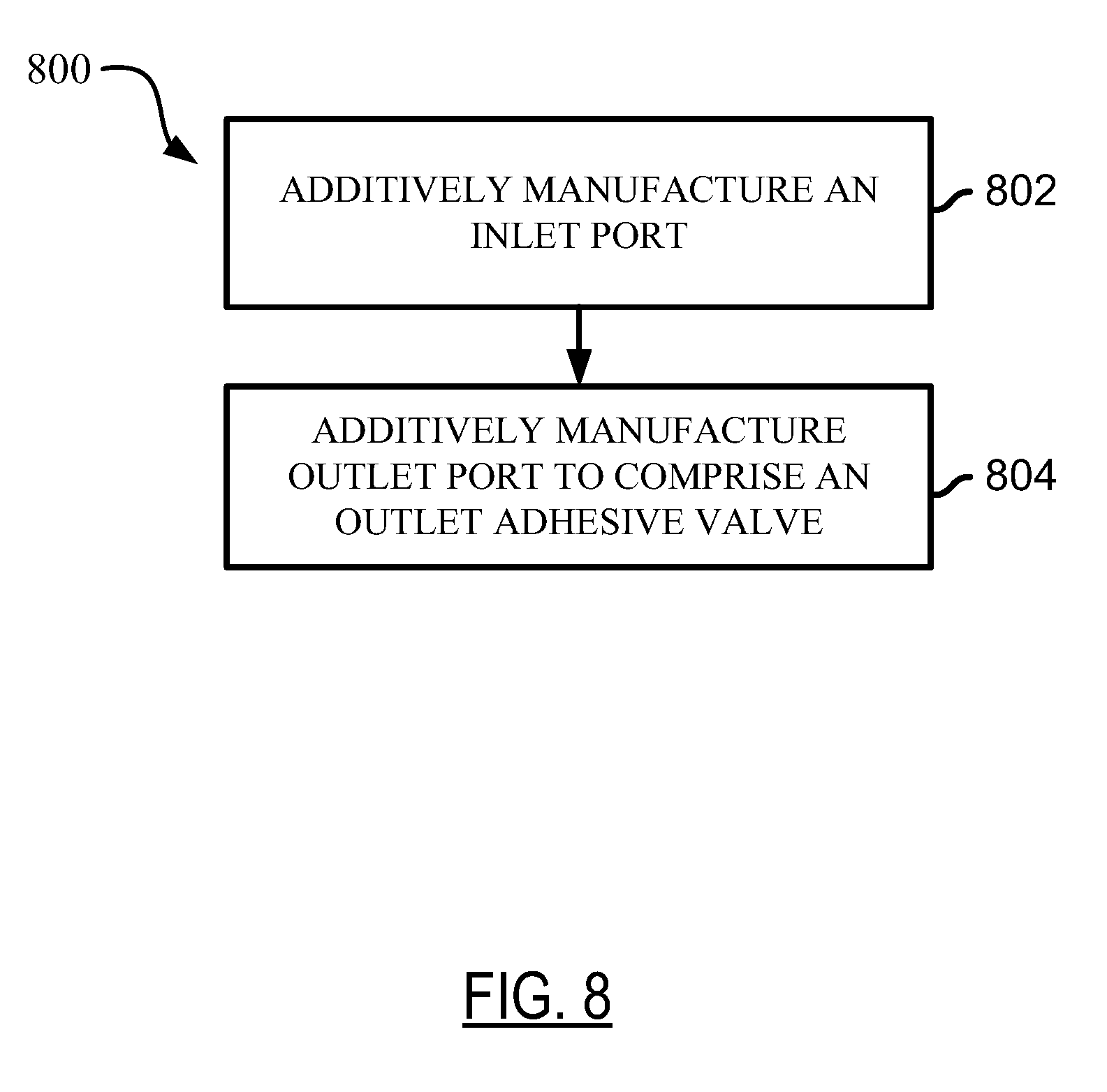
[0076] FIG. 8 illustrates a conceptual flow diagram for additively manufacturing an AM node according to the teachings herein.
[0077] FIG. 9 illustrates a conceptual flow diagram for applying an adhesive to an AM part comprising AM inlet and outlet ports.
[0078] FIG. 10 illustrates a cross section view of an outlet port with a pop-in element installed inside.
DETAILED DESCRIPTION
[0079] The detailed description set forth below in connection with the drawings is intended to provide a description of exemplary embodiments of technology relating to additively manufactured adhesive inlet and outlet ports, and it is not intended to represent the only embodiments in which the invention may be practiced. The term "exemplary" used throughout this disclosure means "serving as an example, instance, or illustration," and should not necessarily be construed as preferred or advantageous over other embodiments presented in this disclosure. The detailed description includes specific details for the purpose of providing a thorough and complete disclosure that fully conveys the scope of the invention to those skilled in the art. However, the invention may be practiced without these specific details. In some instances, well-known structures and components may be shown in block diagram form, or omitted entirely, in order to avoid obscuring the various concepts presented throughout this disclosure.
[0080] The use of additive manufacturing in the context of inlet and outlet ports provides significant flexibility and cost saving benefits that enable manufacturers of mechanical structures and mechanized assemblies to manufacture parts and components with complex geometries at a lower cost to the consumer. The AM inlet and outlet ports described in the foregoing may be used in one or more steps in the process for connecting additively manufactured parts and/or commercial off the shelf (COTS) components. Additively manufactured (AM) parts are printed three-dimensional (3D) parts that are printed by adding layer upon layer of a material based on a preprogrammed design. The parts described in the foregoing may be parts used to assemble a transport structure such as an automobile. However, those skilled in the art will appreciate that the manufactured parts may be used to assemble other complex mechanical products such as vehicles, trucks, trains, motorcycles, boats, aircraft, and the like without departing from the scope of the invention.
[0081] Additive manufacturing provides the ability to create complex structures within a part. For example, a node is a structural member that may include one or more interfaces used to connect to other spanning components such as tubes, extrusions, panels, and the like. Using additive manufacturing, a node may be constructed to include additional features and functions, depending on the objectives. For example, a node may be printed with one or more inlet and outlet ports that enable the ability to secure two or more components by injecting an adhesive rather than traditional welding.
[0082] During adhesive injection, one or more AM part (component) regions are evacuated and hermetically sealed when a vacuum is drawn through channels connecting the inlet and outlet ports. By first evacuating a channel with a vacuum or negative pressure source, a hermetic seal is formed along a channel path. Once the path is completely evacuated, adhesive is injected, and one or more O-rings can ensure that the adhesive hermetically seals the channel and connected channel regions. After the adhesive is cured and a bond forms between the components, O-rings can advantageously maintain the hermetic seal.
[0083] Although the process of drawing a vacuum and applying an adhesive can offer an alternative to conventional welding, adhesive joining does present several challenges. For instance, adhesive may leak out of an inlet and/or outlet port prior to the curing process. This can occur due to backflow following the removal of an adhesive injector at an adhesive inlet port. Also, there can be adhesive leakage upon removal of a vacuum at an outlet part. Unfortunately, backflow and leakage can degrade the adhesive bond quality by introducing air bubbles. Accordingly, there is a need to improve the technology relating to inlet and outlet ports and to develop more effective adhesive injectors to overcome the problems associated with adhesive joining.
[0084] Apparatus and methods for additively manufacturing adhesive inlet and outlet ports are presented herein. Adhesive inlet and outlet ports are additively manufactured to include additively manufactured (AM) valves for reducing and/or eliminating sealant leakage and backflow. Robot end effectors are tailored to interface with the AM inlet and outlet ports and to provide an adhesive source and/or a vacuum source. AM inlet and outlet ports enable robust, lightweight, multi-material AM parts connected via adhesive joining.
[0085] FIG. 1A illustrates a top perspective view 100a of an additively manufactured (AM) part 101 prepared for adhesive sealing according to the teachings herein. The AM part 101 can be a node prepared for joining with other AM parts. For instance, the part 101 can join with tubes, panels, and/or other nodes using adhesive sealing.
[0086] FIG. 1B illustrates a cross section view 100b of the AM part 101 of FIG. 1A using an inlet port 102 and an outlet port 104 according to a first embodiment. The cross section view 100b further illustrates a second component 103 fitted along the outside of the AM part 101. O-rings 106a-d are fitted between the AM part 101 and the second component 103 to improve component sealing.
[0087] A vacuum can be applied to the outlet port 104 and an adhesive (sealant) can be applied at the inlet port 102. The vacuum can draw the sealant through adhesive channels 110a-d so as to fill regions between the AM part 101 and the second component 103. Once the adhesive travels to all regions within the adhesive channels 110a-d and within chambers between the AM part 101 and second component 103, the adhesive can be cured to provide a secure connection.
[0088] According to the teachings herein, the inlet port 102 and the outlet port 104 can use AM valves for reducing and/or eliminating sealant leakage and backflow.
[0089] Although the first embodiment of FIG. 1B shows the inlet port 102 and the outlet port 104 as protruding from AM part 101, other port configurations are possible. For instance, FIG. 1C illustrates a cross section view 100c of the AM part of FIG. 1A using a recessed inlet port 122 and a recessed outlet port 124 according to a second embodiment. Also, although the embodiments shown in cross section views of 100b-c show the AM part 101 are having one inlet port (e.g. inlet port 102 or 122) and one outlet port (e.g. outlet port 104 or 124), other configurations having greater or fewer ports are possible. For instance, an AM part may have more than one inlet port and/or more than one outlet port. In other embodiments, an AM part may use one inlet port to inject adhesive without using a vacuum at an outlet port.
[0090] FIG. 2A illustrates a top perspective view 200a of an AM component 201 with a port using spring-loaded tangs 202a-h according to an embodiment; and FIG. 2B illustrates a top view 200b of the AM component 201 with the port of FIG. 2A. The spring-loaded tangs 202a-h can be co-printed with the AM component 201 to function as an inlet port valve and/or as an outlet port valve.
[0091] FIG. 2C illustrates a top perspective view 200c of a robot head 250 positioned for interfacing at the port of FIG. 2A; and FIG. 2D illustrates a cross section view 200d of the robot head 250 and the port of FIG. 2C. The robot head includes an end effector 252 and alignment O-rings 254a-b for interfacing with the port of AM component 201. The end effector 252 can displace and open the spring-loaded tangs 202a-h by pushing them downward.
[0092] When the port is an input adhesive port, then the end effector 252 can be an adhesive injection effector functioning as a nozzle to displace the tangs 202a-h downward. The effector can inject an adhesive through the port. When the port is an outlet port, the end effector 252 can be configured for drawing a vacuum.
[0093] FIG. 2E illustrates a cross section view 200e of the robot head 250 interfaced with the port of the AM component 201 according to an embodiment. In the embodiment of FIG. 2E, the port is an adhesive inlet port and the end effector 252 is configured for injecting adhesive 257 through an adhesive conduit 256. For purposes of illustration, the cross section view 200e depicts the robot end effector 252 as displacing the tangs 292f and 202c. Although not shown in the cross section view 200e, the robot end effector 252 can displace all spring loaded tangs 202a-h in order to open the port of the AM component 201. The alignment O-rings 254a-b contact the AM component 201 to enhance the seal and ensure the fidelity of the adhesive injection.
[0094] FIG. 2F illustrates a cross section view 200f of the port of the AM component 201 after completion of adhesive injection. As shown, upon completion of the fill, the end effector 252 is removed and the tangs 202c and 202f snap back in place to seal the port and contain adhesive 257.
[0095] FIG. 3A illustrates a cross section view 300a of an AM component 301 with an outlet port using a co-printed ball valve 304 according to an embodiment; and FIG. 3B illustrates the outlet port of FIG. 3A after completion of adhesive injection. The outlet port can be a vacuum port where a vacuum is provided to draw adhesive toward the outlet port in the direction of vector 317; and the ball 306 can co-printed within the ball valve 304.
[0096] When the vacuum is provided, the ball 306 can be displaced so as to allow air passage around the ball. An adhesive may be injected through a conventional port and/or an AM inlet port. The adhesive can flow through adhesive channels within the AM component 301 and be drawn toward the co-printed ball valve 304. As soon as adhesive reaches and flows into the ball valve 304 it can lock the ball 306 into the region 309 as shown in FIG. 3B. In this way the co-printed ball valve realizes a sealed vacuum tight adhesive connection.
[0097] FIG. 4 illustrates a cross section view 400 of an AM component 401 using an outlet port co-printed with a ball valve 404 and AM springs 410 according to an embodiment. The ball valve 404 is similar to ball valve 304 except it uses AM springs 410 which are added at an opening to lock the ball 406. The AM springs 410 can either be co-printed, or added after printing the AM component 401. The AM springs 410 can ensure that the ball 406 does not block the outlet port prematurely, thereby allowing airflow around the ball 406 through the AM springs 410.
[0098] The AM springs 410 can be printed to have a mesh size and geometrical features which impede the flow of adhesive. The air and adhesive flow, shown by vector 420, continues until adhesive reaches and fills the ball valve 404. The adhesive injection pressure may then lock the ball 406 and the AM springs 410 into place, thereby sealing the ball valve 404 and advantageously preventing adhesive spillage due to the impeding action of the AM springs 410.
[0099] FIG. 5A illustrates a cross section view 500a of an AM component 501 using an AM inlet port valve 504 co-printed with a lattice 510 according to an embodiment. The co-printed lattice 510 can be co-printed with an orientation and geometry so as to ensure unidirectional flow. The lattice 510 can be co-printed so as to facilitate flow in the adhesive inflow direction shown by vector 520 while impeding flow opposite to vector 520. In this way adhesive can flow into the AM component 501 and opposite backflow can be reduced and/or eliminated.
[0100] FIG. 5B illustrates a cross section view 500b of the AM component 501 using an AM outlet port valve 524 co-printed with a lattice 530 according to an embodiment. The embodiment of FIG. 5B is similar to that of FIG. 5A, except the lattice 530 is oriented so as to impede adhesive flow as the adhesive enters the outlet port valve 524 along the flow vector 540. The lattice 530 can be co-printed to provide a reduced volume for flow.
[0101] A pressure spike resulting from the adhesive flow at the lattice 530 can be used in automating adhesive injection into the AM component 501. For instance, the resulting pressure spike can be used as a signal to a control module to send instructions for terminating adhesive injection. In this way the lattice 530 can advantageously operate as a flow sensor which senses, via pressure spikes, when to terminate injection. Additionally, the lattice 530 can advantageously prevent adhesive leakage out of the AM component 501.
[0102] FIG. 6A illustrates a cross section view 600a of an AM component 601 using a co-printed flap 605 as an inlet port valve according to an embodiment. The co-printed flap 605 with the extension 612 can function as a valve to ensure unidirectional flow in the direction of flow vector 610. The flap 605 can be configured to deflect away from the extension 612 during adhesive injection, and can prevent flow of the adhesive in the direction opposite to the flow vector 610. Flow is prevented and/or impeded in the opposite direction when the flap 605 pushes against the extension 612 to prevent flow.
[0103] FIG. 6B illustrates a cross section view 600b of an AM component 621 using a co-printed flap 625 as an outlet port valve according to an embodiment. In this embodiment the flap 625 functions similar to flap 605 except the flow direction is in the direction of flow vector 620. The outlet port valve includes a first extension 622 and a second extension 624 which facilitate vacuum air flow in the direction of the flow vector 620 while impeding adhesive flow in the direction of flow vector 620. Thus, once the adhesive reaches the output port valve and the AM part 621 is completely filled, the valve can lock into place and prevent outflow.
[0104] FIG. 7A illustrates a cross section view 700a of a multifunctional end effector 702 positioned for connection with an AM port 706. The AM port 706 extends from the surface 712 of the AM part 701 and can serve as an inlet port for injecting adhesive and/or as a vacuum port for drawing an adhesive via the vacuum.
[0105] When used for adhesive injection at the AM port 706, the multifunctional end effector 702 can provide at least two functions: adhesive injection, and post injection plugging. As shown in FIG. 7A, post injection plugging can be effected through a first channel 704 holding a plug 709; and adhesive injection can be effected through a second channel 703. During adhesive injection, adhesive flows through the second channel 703 and into the AM port 706 through a channel 707. Upon completion of the fill, a section 708 of the AM port 706 is additively manufactured and available as a plug acceptor feature to receive and hold the plug 709. For example, the plug 709 may be snapped into place at section 708 when the fill is completed. A partition 705 can be used to route the adhesive injected through the second channel 703 into the AM port 706.
[0106] FIG. 7B illustrates a cross section view 700b of the multifunctional end effector 702 of FIG. 7A connected with the AM port 706 for adhesive injection. As shown in FIG. 7B, the multifunctional end effector 702 fits over the AM port 706 and can contact the surface 712. Adhesive flows along flow vector 720 and into the AM port 706.
[0107] FIG. 7C illustrates a cross section view 700c of the multifunctional end effector 702 of FIG. 7A. On completion of the adhesive fill, the partition 705 blocks the second channel 703; and the plug 709 is inserted from the first channel 704 in the direction of vector 724.
[0108] FIG. 7D illustrates a cross section view 700d of the AM port 706 following the adhesive injection and sealing by the multifunctional end effector of FIG. 7A. The plug 709 snaps into place at the co-printed plug acceptor region 708 (FIG. 7A). Using the multifunctional end effector 704 can advantageously reduce and/or eliminate the need for pressure equalization. This in turn can reduce air gulping, a phenomenon which occurs when conventional injection effectors are disconnected.
[0109] In some embodiments the AM port 706 can be an outlet port for operating as a conventional vacuum port. In other embodiments the AM port 706 can be co-printed with mesh, a pop-in element, or another structure designed to ease the process flow.
[0110] FIG. 8 illustrates a conceptual flow diagram 800 for additively manufacturing an AM node according to the teachings herein. In step 802 an inlet port is additively manufactured; and in step 804 an outlet port is additively manufactured with an outlet adhesive valve. The outlet adhesive valve can comprise the AM outlet port valve features presented above. For instance, the AM outlet valve can be a ball valve or use co-printed tangs. In some embodiments the inlet port can also include a co-printed inlet valve as discussed in FIGS. 1A-7D.
[0111] FIG. 9 illustrates a conceptual flow diagram 900 for applying an adhesive to an AM part comprising AM inlet and outlet ports. The AM part can comprise any of the AM components/parts having both AM inlet and outlet ports as described above. In step 902 an adhesive is provided at an AM inlet port. In step 904 adhesive flow is facilitated from the inlet port to the outlet port using an AM port valve. In this step a vacuum can optionally be attached to an outlet port. An AM inlet port valve and/or an AM outlet port valve may be used in the inlet and outlet ports, respectively. For instance, the co-printed ball valve of FIGS. 3A-B may be used to facilitate unidirectional flow. Step 906 is a decision step to determine if the adhesive flow is complete. If the flow is not complete, then the flow diagram returns to step 904 and adhesive continues to flow. In order to determine if the flow is complete a pressure sensor such as lattice 530 can be used in a control system to determine when to exit the decision step. If the adhesive flow is complete and adhesive has reached the outlet port, then the flow diagram terminates adhesive flow at step 908, e.g., as described in the embodiments of FIGS. 7C-D, above.
[0112] FIG. 10 illustrates a cross section view of an adhesive outlet port 1015 with a pop-in element 1009 installed inside outlet port 1015 of the AM component 1011. In this embodiment, the pop-in element 1009 may be utilized to determine when the AM component 1011 has reached the adhesive full point. The pop-in element 1009 may be made of a material such as an elastomer. The element 1009 would be configured to pop into the adhesive outlet port 1015 by the application of some pressure, which action may temporarily disfigure the pop-in element. The element 1009 would have sufficient elasticity to spring back to its original dimensions after it has been popped into the adhesive outlet port. The diameter (or opening profile) of the adhesive outlet port 1015 may in an embodiment be smaller than the pop-in element 1009 in its original shape, such that pop-in element 1009 may effectively captured in the port 1015.
[0113] In operation, the pop-in element 1009 would be a mesh-like or restrictor element. In this capacity, the element 1009 would allow for air to be drawn through it. However, when an adhesive 999 flows through it from inner channels 1011 as it is attracted to the vacuum (or solely is pushed by a force from the adhesive inlet port, where no vacuum is applied), a restricted flow 1004 indicative of a sudden pressure change or pressure spike would be produced. This restricted flow 1004 may be recorded during the adhesive injection process and would indicate a complete fill. The adhesive injection apparatus would then be disconnected. Depending on the elasticity of the pop-in element 1009 and other characteristics, the pressure building from the restricted flow 1004 may result in a sufficient upward pressure on the element 1009 to selectively disfigures it or, in some embodiments, lodges it out of place. The restricted flow 1004 is intended to conceptually convey that a sudden change of pressure in the direction of arrow 1010 can be observed at the outlet port by virtue of the pop-in element 1009. It does not necessarily mean that the restricted flow will resemble the illustration exactly.
[0114] The previous description is provided to enable any person skilled in the art to practice the various aspects described herein. Various modifications to these exemplary embodiments presented throughout this disclosure will be readily apparent to those skilled in the art, and the concepts disclosed herein may be applied to other techniques for additively manufacturing adhesive inlet and outlet ports. Thus, the claims are not intended to be limited to the exemplary embodiments presented throughout the disclosure, but are to be accorded the full scope consistent with the language claims. All structural and functional equivalents to the elements of the exemplary embodiments described throughout this disclosure that are known or later come to be known to those of ordinary skill in the art are intended to be encompassed by the claims. Moreover, nothing disclosed herein is intended to be dedicated to the public regardless of whether such disclosure is explicitly recited in the claims. No claim element is to be construed under the provisions of 35 U.S.C. .sctn. 112(f), or analogous law in applicable jurisdictions, unless the element is expressly recited using the phrase "means for" or, in the case of a method claim, the element is recited using the phrase "step for."
* * * * *
D00000
D00001
D00002
D00003
D00004
D00005
D00006
D00007
D00008
D00009
D00010
D00011
D00012

D00013

D00014

D00015

D00016
D00017

D00018

XML
uspto.report is an independent third-party trademark research tool that is not affiliated, endorsed, or sponsored by the United States Patent and Trademark Office (USPTO) or any other governmental organization. The information provided by uspto.report is based on publicly available data at the time of writing and is intended for informational purposes only.
While we strive to provide accurate and up-to-date information, we do not guarantee the accuracy, completeness, reliability, or suitability of the information displayed on this site. The use of this site is at your own risk. Any reliance you place on such information is therefore strictly at your own risk.
All official trademark data, including owner information, should be verified by visiting the official USPTO website at www.uspto.gov. This site is not intended to replace professional legal advice and should not be used as a substitute for consulting with a legal professional who is knowledgeable about trademark law.