Apparatus For Introducing A Steerable Camera Assembly Into A Patient
Griffith; David B. ; et al.
U.S. patent application number 16/278529 was filed with the patent office on 2019-10-24 for apparatus for introducing a steerable camera assembly into a patient. The applicant listed for this patent is Ethicon LLC. Invention is credited to Kempton K. Carroll, II, Sean P. Conlon, David B. Griffith, Christopher J. Hess, William B. Weisenburgh, II.
| Application Number | 20190321073 16/278529 |
| Document ID | / |
| Family ID | 49549140 |
| Filed Date | 2019-10-24 |


View All Diagrams
| United States Patent Application | 20190321073 |
| Kind Code | A1 |
| Griffith; David B. ; et al. | October 24, 2019 |
APPARATUS FOR INTRODUCING A STEERABLE CAMERA ASSEMBLY INTO A PATIENT
Abstract
A cannula sleeve for a surgical trocar assembly. The cannula sleeve includes a hollow shaft, at least a portion of which is made of a rigid material, and a seal at the distal end of the hollow shaft, the seal being movable between a first open position and a second closed position. The shaft defines a proximal end, a distal end, a periphery, and a longitudinal axis. The shaft further includes a channel at the periphery substantially parallel to the longitudinal axis, the channel being in communication with the hollow shaft.
| Inventors: | Griffith; David B.; (Cincinnati, OH) ; Conlon; Sean P.; (Loveland, OH) ; Weisenburgh, II; William B.; (Maineville, OH) ; Hess; Christopher J.; (Blue Ash, OH) ; Carroll, II; Kempton K.; (San Clemente, CA) | ||||||||||
| Applicant: |
|
||||||||||
|---|---|---|---|---|---|---|---|---|---|---|---|
| Family ID: | 49549140 | ||||||||||
| Appl. No.: | 16/278529 | ||||||||||
| Filed: | February 18, 2019 |
Related U.S. Patent Documents
| Application Number | Filing Date | Patent Number | ||
|---|---|---|---|---|
| 15226588 | Aug 2, 2016 | 10206709 | ||
| 16278529 | ||||
| 13470781 | May 14, 2012 | 9427255 | ||
| 15226588 | ||||
| Current U.S. Class: | 1/1 |
| Current CPC Class: | A61B 17/3474 20130101; A61B 17/3462 20130101; A61B 2017/3445 20130101; A61B 17/3423 20130101; A61B 1/3132 20130101; A61B 17/3421 20130101; A61B 1/041 20130101; A61B 1/00154 20130101; A61B 2017/00283 20130101; A61B 1/00158 20130101 |
| International Class: | A61B 17/34 20060101 A61B017/34; A61B 1/04 20060101 A61B001/04; A61B 1/313 20060101 A61B001/313; A61B 1/00 20060101 A61B001/00 |
Claims
1-17. (canceled)
18. A cannula sleeve for a surgical trocar assembly, comprising: a hollow shaft at least a portion of which is made of a rigid material, the shaft defining a proximal end, a distal end, a periphery, and a longitudinal axis, the shaft including a channel at the periphery substantially parallel to the longitudinal axis, the channel being in communication with the hollow shaft; and a seal at the distal end of the hollow shaft, the seal being movable between a first open position and a second closed position.
19. The cannula sleeve of claim 18, wherein the channel includes open proximal and distal ends, and wherein the open distal end bypasses the seal.
20. The cannula sleeve of claim 18, wherein the seal comprises a duckbill seal.
21. The cannula sleeve of claim 18, further comprising a flange at the proximal end of the hollow shaft, and wherein the channel includes an opening through the flange.
22-23. (canceled)
24. The cannula sleeve of claim 18, wherein the channel is sized to receive a camera tether therethrough.
25. The cannula sleeve of claim 18, wherein the seal is biased to the second closed position such that the seal transitions from the first open position to the second closed position absent the surgical trocar assembly.
26. The cannula sleeve of claim 18, wherein the rigid material is configured to maintain its shape against pressure exerted by a cavity into which the cannula sleeve is inserted absent the surgical trocar assembly.
27. A cannula sleeve for an endoscopic device, the cannula sleeve comprising: a tubular shaft comprising a rigid portion, a passage, a periphery extending about the passage, a longitudinal axis, a first shaft end, and a second shaft end; a channel extending along the periphery of the passage parallel to the longitudinal axis, the channel comprising a first channel end and a second channel end; wherein the channel is in fluid communication with the passage; and a seal at the second shaft end, the seal configured to transition between an open position and a closed position in which the second shaft end is covered from being in fluid communication with a cavity into which the cannula sleeve is inserted; and wherein the second channel end is uncovered by the seal in the closed position.
28. The cannula sleeve of claim 27, wherein the seal is selected from the group consisting of a duckbill seal and a clamshell seal.
29. The cannula sleeve of claim 27, further comprising a flange at the first shaft end, the flange comprising a first width that is greater than a second width of the tubular shaft.
30. The cannula sleeve of claim 27, wherein the channel is sized to receive a camera tether therethrough.
31. The cannula sleeve of claim 27, wherein the seal is biased to the closed position such that the seal transitions from the first position to the second position absent the endoscopic device.
32. The cannula sleeve of claim 27, wherein the rigid portion is configured to maintain its shape against pressure exerted by a cavity into which the cannula sleeve is inserted absent the endoscopic device.
Description
CROSS-REFERENCE TO RELATED APPLICATIONS
[0001] This application is a divisional application claiming priority under 35 U.S.C. .sctn. 121 to U.S. patent application Ser. No. 15/226,588, filed Aug. 2, 2016, entitled APPARATUS FOR INTRODUCING AN OBJECT INTO A PATIENT, which issues on Feb. 19, 2019 as U.S. Pat. No. 10,206,709, which is a divisional application claiming priority under 35 U.S.C. .sctn. 121 to U.S. patent application Ser. No. 13/470,781, filed May 14, 2012, entitled APPARATUS FOR INTRODUCING A STEERABLE CAMERA ASSEMBLY INTO A PATIENT, which issued on Aug. 30, 2016 as U.S. Pat. No. 9,427,255, the entire disclosure of which is hereby incorporated by reference herein.
BACKGROUND
[0002] Endoscopic surgery in the abdominal cavity of an animal, such as, for example, a human, may include insufflating the abdomen to create a space in which surgeons may introduce endoscopic surgical instruments. Access to the abdomen may be created with a trocar assembly, which may include a hollow cannula and a solid shaft passing through the cannula. The solid shaft may include a sharp tip that pierces the abdominal wall to form an otomy and that guides the cannula partially into the insufflated abdominal cavity. After the cannula is in place in the otomy, the solid shaft may be withdrawn from the cannula, leaving a passage through the cannula that the surgeon may use to access the abdominal cavity using endoscopic surgical devices. The cannula may include a seal, such as a duck bill seal, at its distal end that is biased in a closed position to prevent or retard the escape of gases insufflating the abdomen. A surgeon chooses a trocar size that closely fits the endoscopic tools he intends to introduce therethrough. For example, if the endoscopic tool to be used has a diameter of 14 millimeters, then a cannula having an inner diameter of slightly more than 14 millimeters would be used. The endoscopic tool passes through the cannula and opens the seal on the cannula. The close sizing between the endoscopic tool and the cannula prevents or retards the escape of the gasses insufflating the abdomen that would otherwise pass through the open seal.
[0003] Magnetic anchoring and guidance systems (MAGS) have been developed for use in minimally invasive procedures. MAGS include an internal device attached in some manner to a surgical instrument, laparoscope or other camera or viewing device, and an external hand held device or external control unit ("ECU") for controlling the movement of the internal device. Each of the external and internal devices has magnets which are magnetically coupled to each other across, for example, a patient's abdominal wall. In the current systems, the external magnet may be adjusted by varying the height of the external magnet.
[0004] The camera is attached to one or more tethers that provide power to the camera's electronics, image date, and, optionally, water or gases. The tethers lead out through the cannula and pass through the seal on the cannula. The presence of the tether prevents the seal on currently-available cannulas from closing, thereby creating a leak that enables the insufflation gases to escape when other endoscopic surgical instruments are not placed in the cannula.
[0005] The foregoing discussion is intended only to illustrate various aspects of the related art in the field of the invention at the time, and should not be taken as a disavowal of claim scope.
SUMMARY OF THE INVENTION
[0006] Embodiments described herein provide a cannula assembly with a seal for a tether of an internal magnetic camera. The cannula assembly may include a housing that includes a distal opening and a proximal opening with a passage therebetween. The housing may be configured to have a cannula tube attached in a manner that the cannula tube is in fluid communication with the distal opening. A plurality of compliant membranes may be arranged as a stack anywhere in the passage or in the proximal or distal openings. The compliant membranes may be made of any compliant material, such as, for example, silicone, latex, or rubber. In various embodiments, the stack may include two compliant membranes. In various other embodiments, the stack may include three compliant membranes. Each membrane includes an aperture that may open to accommodate an internal magnetic camera or its tether, or any other endoscopic device that is passed through the membranes. The apertures may be arranged such that, when the compliant membranes are stacked, each aperture does not overlap with remaining apertures.
[0007] In certain embodiments in which the stack includes at least three compliant membranes, one of the apertures may comprise a slit, and the compliant membrane in which the slit is formed is sandwiched between two membranes having apertures of a different configuration, such as, for example, apertures having circular shapes. In certain other embodiments in which the stack includes at least three compliant membranes, each aperture may comprise a wedge-shaped gap formed in its respective compliant membrane, and, the compliant membranes may be arranged such that, when they are arranged in a stack, each wedge-shaped gap does not overlap with remaining wedge-shaped gaps.
[0008] In various embodiments, the membranes may include a plurality of engagement members that are configured to couple to engagement members in the passage or one of the proximal and distal openings of the cannula housing. In certain embodiments, coupling of the respective membranes may result in each of the compliant membranes being stretched in a region between its engagement members. In certain embodiments, the engagement members of the cannula housing may comprise a plurality of posts around a periphery of the passage or one of the proximal or distal openings, and the engagement members on each of the compliant membranes may comprise a plurality of holes around the periphery each membrane that fit over the posts. A retaining ring may be placed on the membranes to retain them in the passage or in the proximal or distal openings.
[0009] In various embodiments, the cannula housing may be configured include an upper housing in fluid communication with the proximal opening. The upper housing may include a port or several ports configured to receive tethers of the camera, and the ports are distinct from an opening in the upper housing that is configured to receive other endoscopic instruments. The ports may include gaskets that provide a tight seal against the tethers.
[0010] In various embodiments, the cannula housing may include a first face and a second face, and each of the first and second faces includes a proximate opening. Each of the two proximate openings has a plurality of compliant membranes and apertures. The two proximate openings are at an angle relative to each other, and each of the two openings is in fluid communication with the passage in the cannula housing. The housing is configured to rotate in a bracket between a first position and a second position. In the first position, a first of the two proximate openings is aligned with the distal opening via the passage. In the second position, a second of the proximate openings is aligned with the distal opening via the passage.
[0011] In various embodiments, a cannula assembly includes a cannula tube and the seal comprises a sleeve encasing at least a portion of the tube. The sleeve may include a seal at its distal end, such as, for example, a duck bill seal or a clam shell seal. The sleeve also may include a channel on its periphery and substantially parallel to a longitudinal axis of the cannula tube. The channel is configured to receive a tether for an internal magnetic camera. The channel may include open distal and proximal ends such that the tether bypasses the seal. In use, after the surgeon inserts the cannula tube into a body cavity through an otomy, the cannula tube may be removed, leaving the sleeve positioned in the otomy. The seal at the distal end of the sleeve inhibits the escape of insufflation gases from the body cavity. The surgeon may then push the camera into the body cavity through the sleeve. After the camera is positioned in the body cavity, the camera tether may be pushed into the tether such that it is out of the way for additional endoscopic instruments that may be placed in the sleeve.
BRIEF DESCRIPTION OF THE DRAWINGS
[0012] Various features of the embodiments described herein are set forth with particularity in the appended claims. The various embodiments, however, both as to organization and methods of operation, together with advantages thereof, may be understood in accordance with the following description taken in conjunction with the accompanying drawings as follows.
[0013] FIG. 1A is a perspective view of a trocar and obturator assembly according to an embodiment of the present invention;
[0014] FIG. 1B is a perspective view of the trocar assembly of FIG. 1A with an obturator assembly removed;
[0015] FIG. 2A is a perspective exploded view of a cannula housing and compliant membranes according to an embodiment of the present invention;
[0016] FIG. 2B is a perspective view of the cannula housing and compliant membranes of FIG. 2A;
[0017] FIG. 2C is a top view of the cannula housing and compliant membranes of FIG. 2B;
[0018] FIG. 3A is a perspective exploded view of a cannula housing and compliant membranes according to another embodiment of the present invention;
[0019] FIG. 3B is a perspective view of the top of the assembled cannula housing and compliant membranes of FIG. 3A;
[0020] FIG. 4A is a perspective exploded view of a cannula housing and compliant membranes according to another embodiment of the present invention;
[0021] FIG. 4B is a top view of compliant membranes according to another embodiment of the present invention, showing apertures in respective membranes in broken line;
[0022] FIG. 4C is a top view of compliant membranes according to another embodiment of the present invention, showing apertures in respective membranes in broken line;
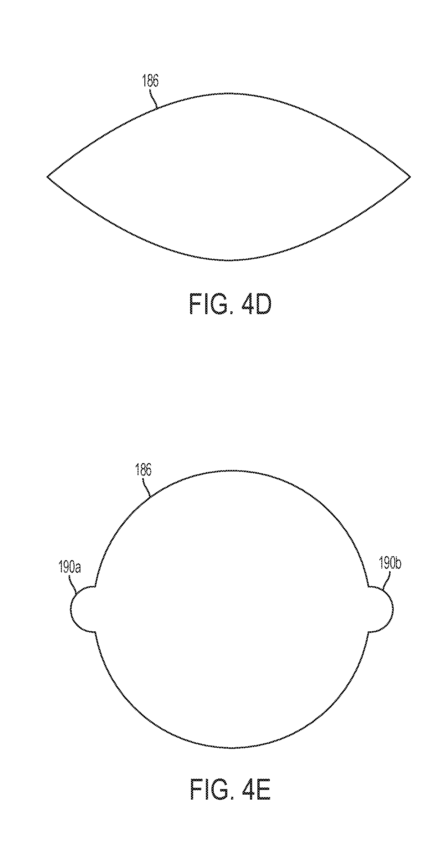
[0023] FIG. 4D is a top view of a slit aperture in a compliant membrane with no relief cuts at its ends in a stretched open configuration;
[0024] FIG. 4E is a top view of a slit aperture in a compliant membrane with relief cuts at its ends in a stretched open configuration;
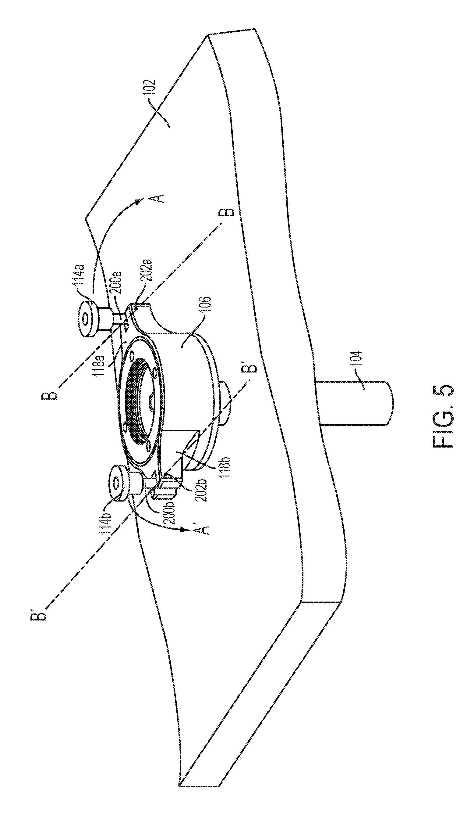
[0025] FIG. 5 is a perspective view of a cannula housing positioned in tissue according to an embodiment of the present invention;
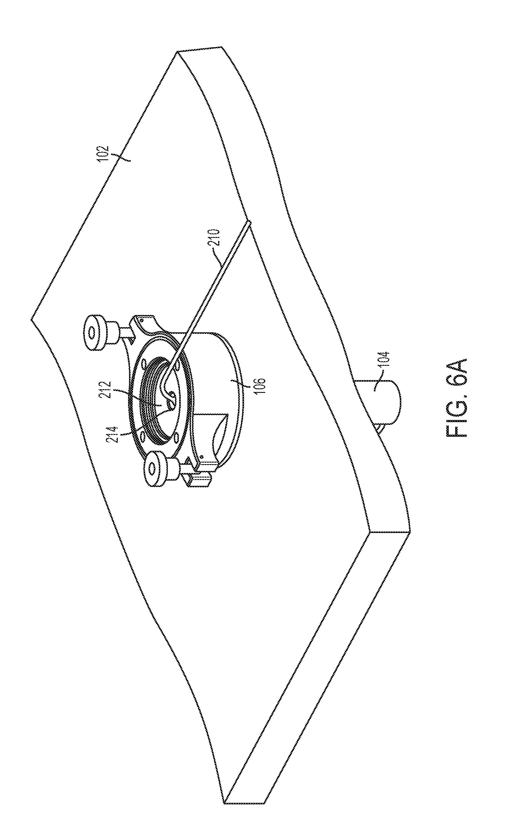
[0026] FIG. 6A is a perspective view of a cannula housing according to an embodiment of the present invention with a tether disposed therethrough;
[0027] FIG. 6B is a perspective view of the cannula housing of FIG. 6A showing a camera in an internal site of a patient attached to the tether;
[0028] FIG. 7 is an embodiment of a cannula and trocar assembly according to an embodiment of the present invention showing a tether passing through a port on the cannula housing and an internally positioned camera;
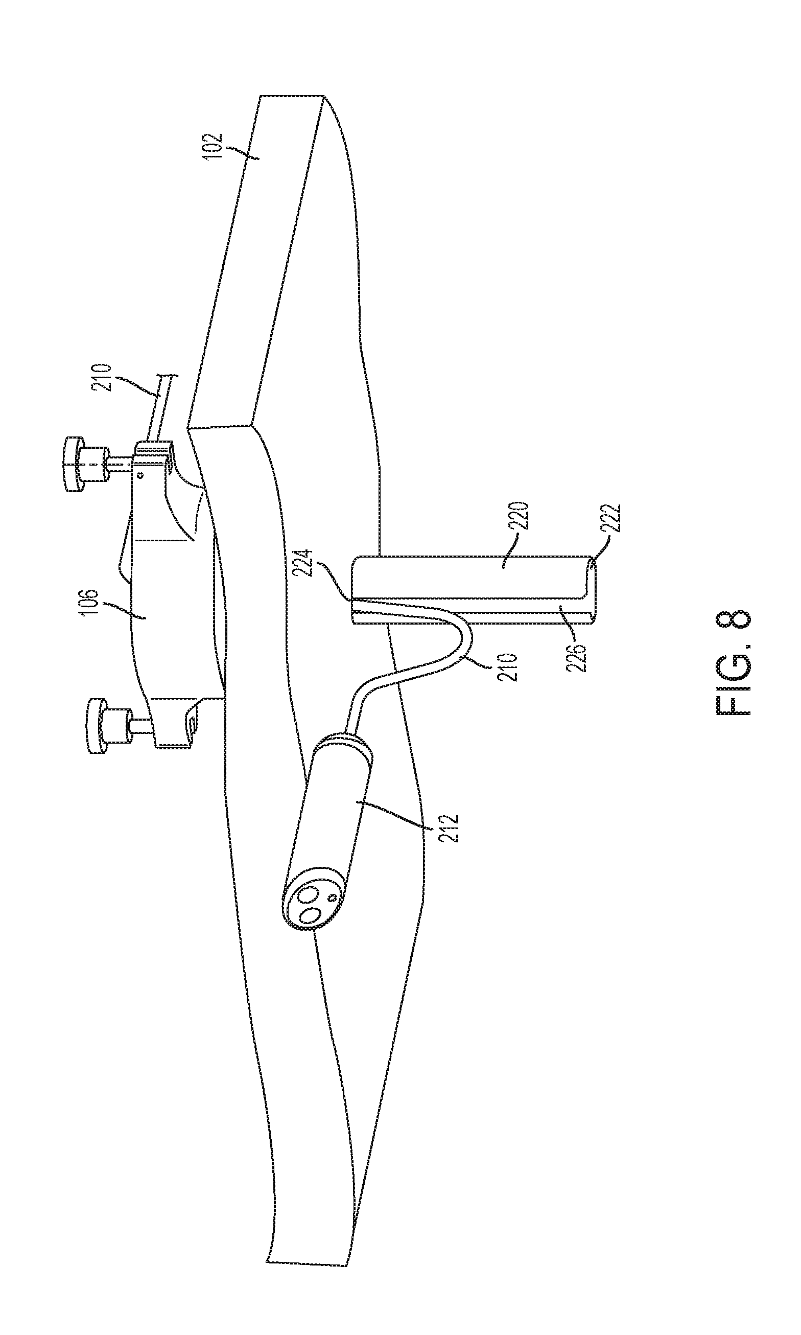
[0029] FIG. 8 is an embodiment of a cannula and tethered housing from the perspective of an internal site of the patient;
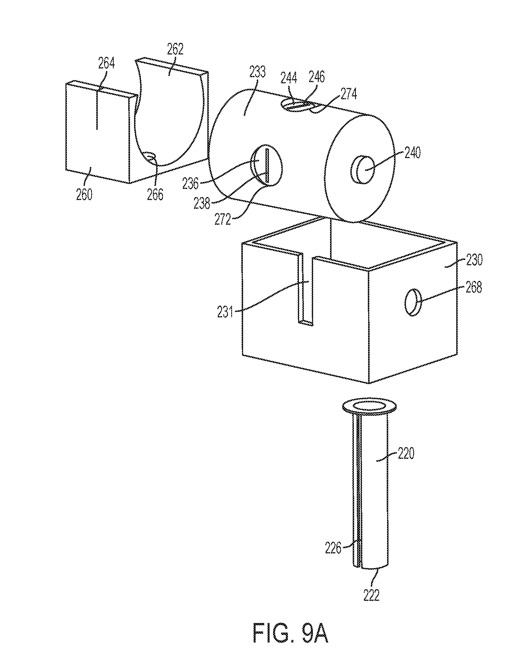
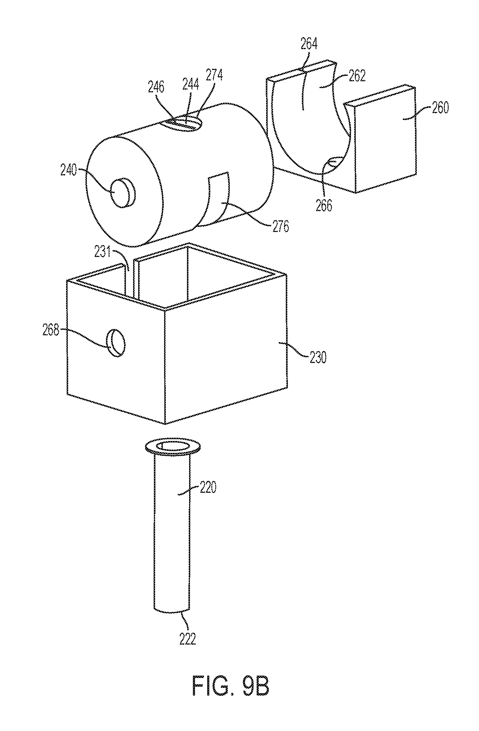
[0030] FIG. 9A is a front exploded view of a cannula tube and housing according to an alternative embodiment of the present invention;
[0031] FIG. 9B is a rear exploded view of the cannula tube and housing of FIG. 9A;
[0032] FIG. 9C is a front perspective view of the cannula tube and housing of FIG. 9A with a tether passing therethrough, wherein the bracket is shown as clear for visibility of the housing;
[0033] FIG. 9D is a rear perspective view of the cannula tube and housing of FIG. 9A with the tether passing therethrough, wherein the bracket is shown as clear for visibility of the housing;
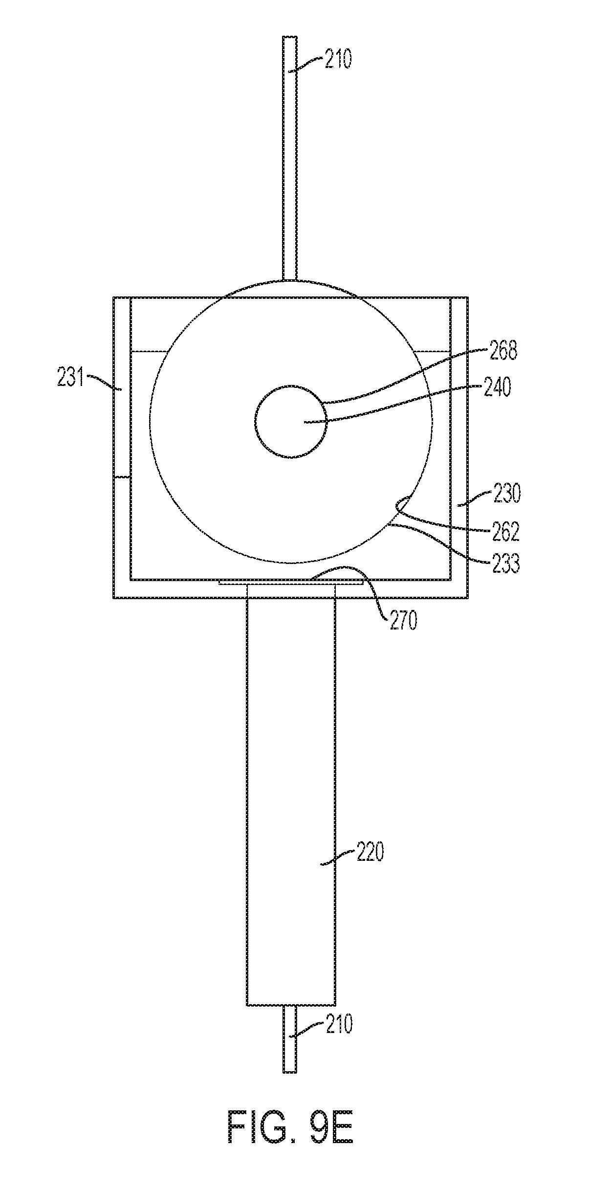
[0034] FIG. 9E is a side view of the cannula tube and housing of FIG. 9A with the tether passing therethrough, wherein the bracket is shown as clear for visibility of the housing;
[0035] FIG. 9F is a front perspective view of the cannula tube and housing of FIG. 9A with the tether passing therethrough, wherein the bracket is shown as clear for visibility of the housing;
[0036] FIG. 9G is a perspective view of the cannula tube and housing of FIG. 9F with the tether passing therethrough, wherein the housing is moved to a rotated positioned;
[0037] FIG. 9H is a second perspective view of the cannula tube and housing of FIG. 9F with the tether passing therethrough, wherein the housing is moved to a rotated positioned;
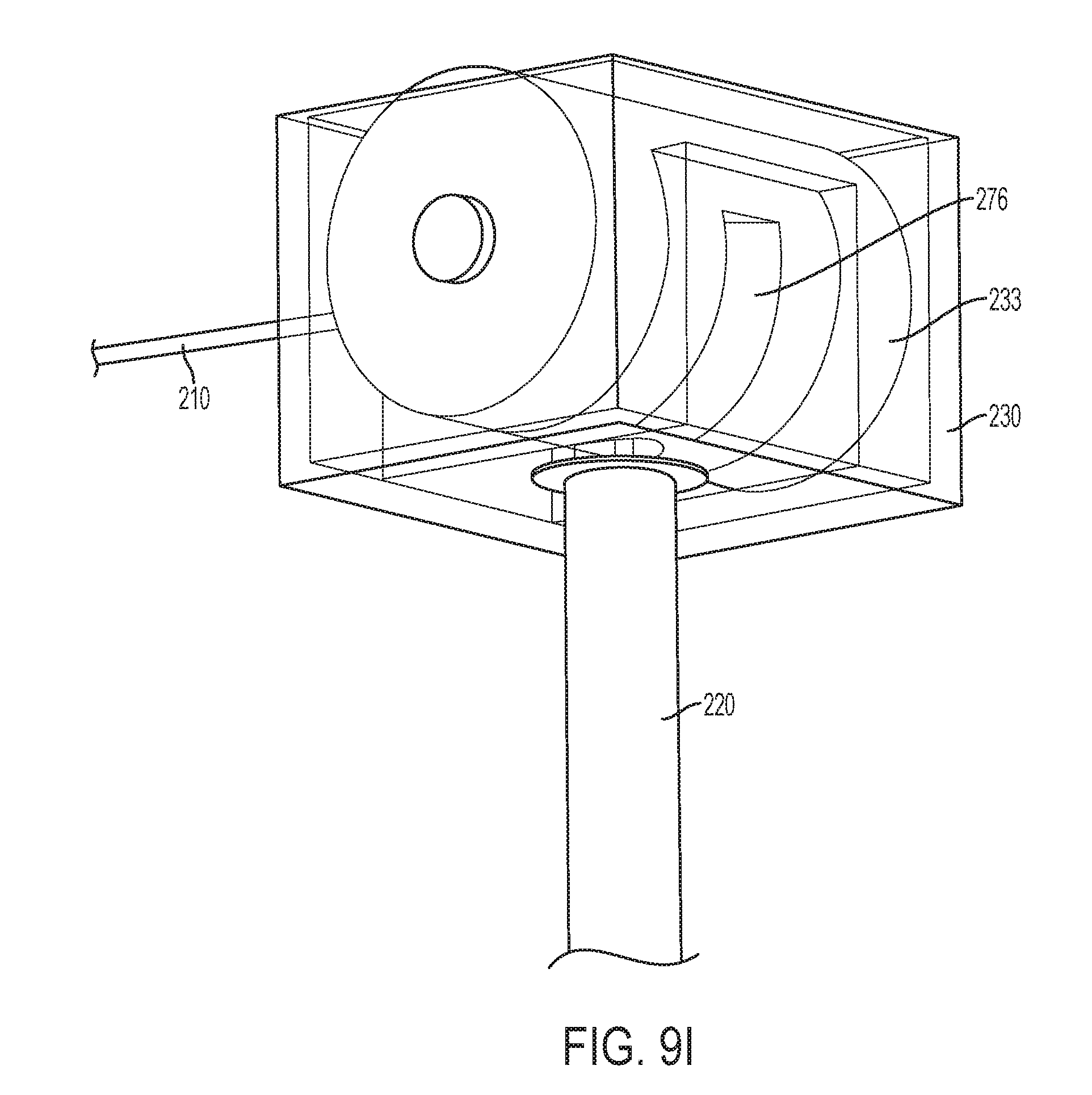
[0038] FIG. 9I is a third perspective view of the cannula tube and housing of FIG. 9H with the tether passing therethrough, wherein the housing is moved to a rotated positioned;
[0039] FIG. 10A is a perspective view of a trocar and obturator assembly according to an embodiment of the present invention;
[0040] FIG. 10B is a perspective view of the trocar assembly of FIG. 10A wherein an obturator assembly is removed;
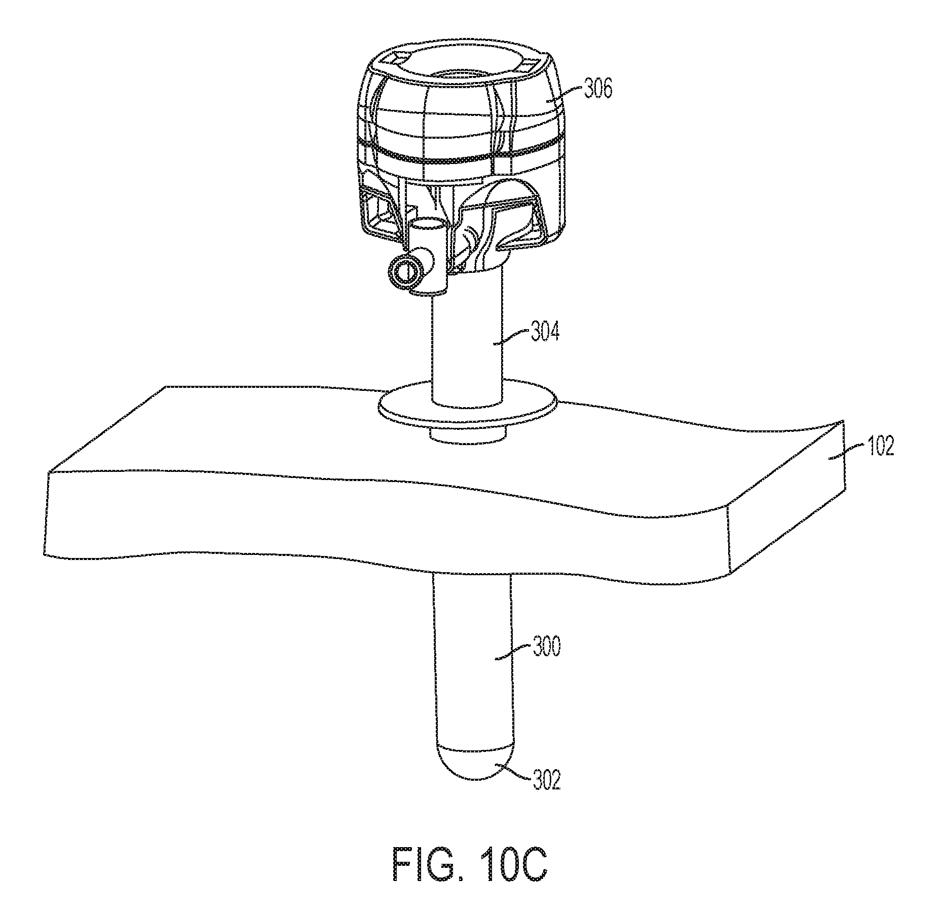
[0041] FIG. 10C is a perspective view of the trocar assembly of FIG. 10B wherein a cannula assembly is partially removed from an embodiment of a cannula sleeve, showing a seal on the sleeve in a closed position;
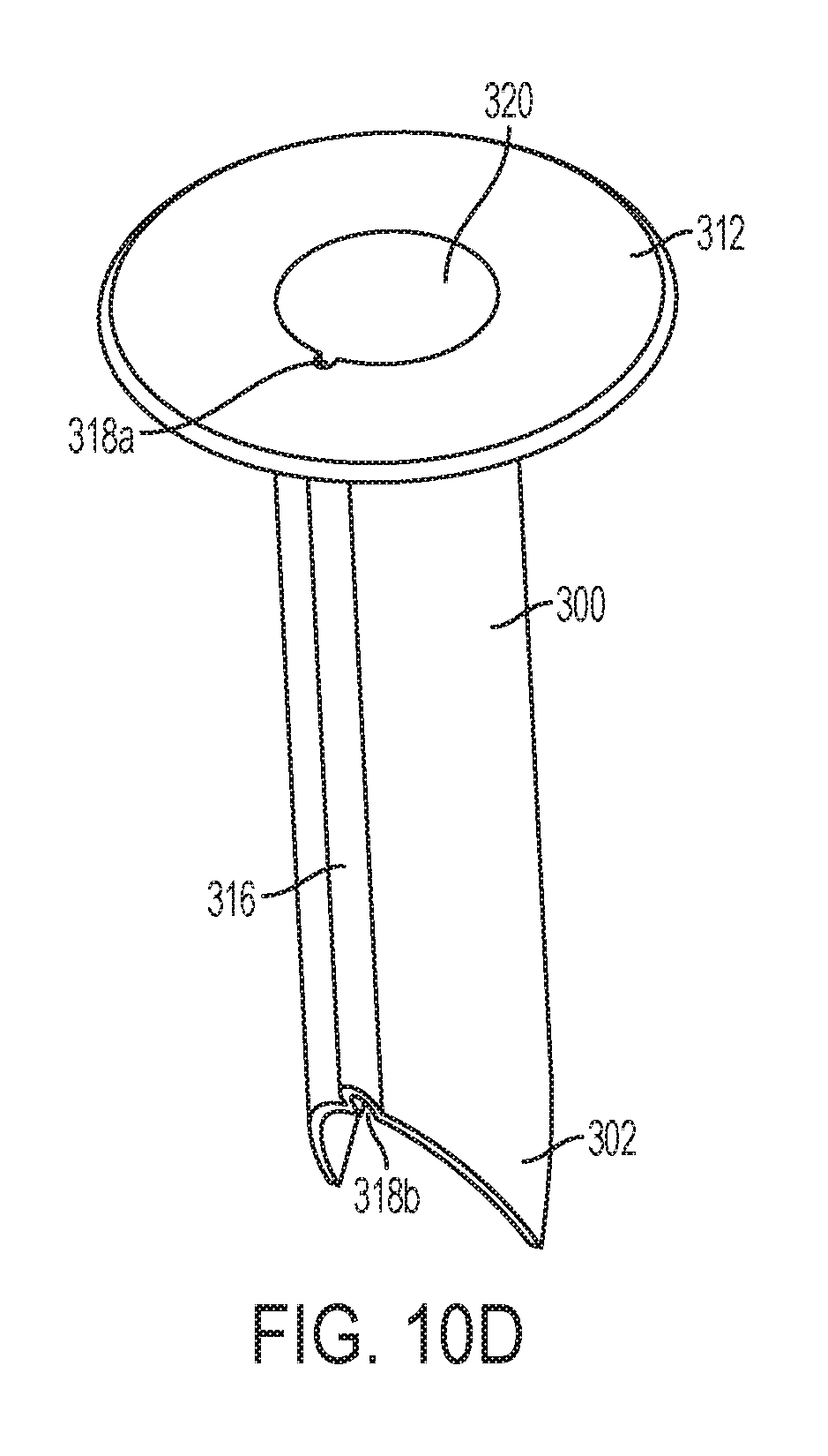
[0042] FIG. 10D is a perspective view of an embodiment of a cannula sleeve of the trocar assembly of FIG. 10A, showing the seal on the sleeve in an open position;
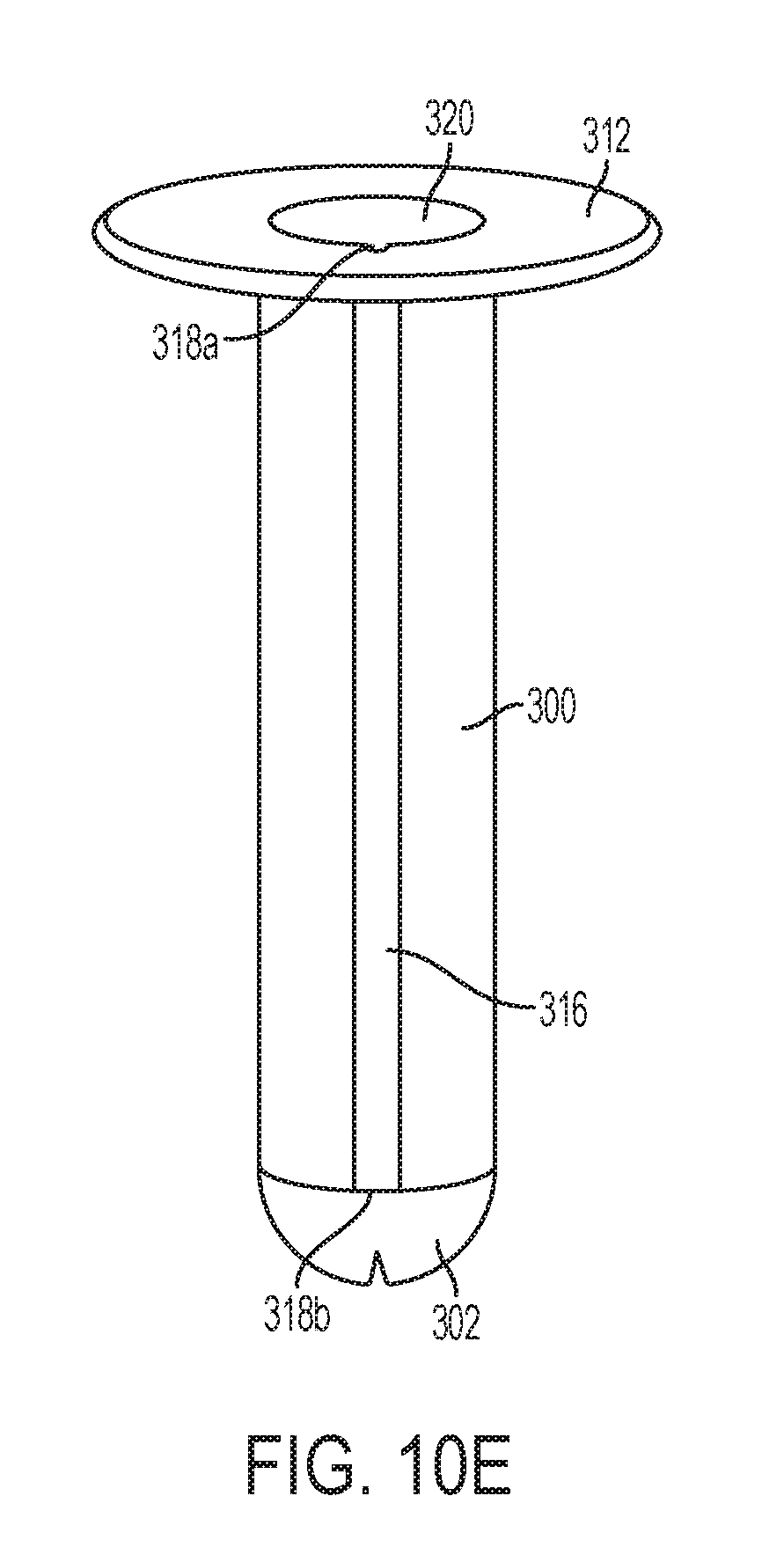
[0043] FIG. 10E is a perspective view of the cannula sleeve of FIG. 10D showing the seal on the sleeve in the closed position;
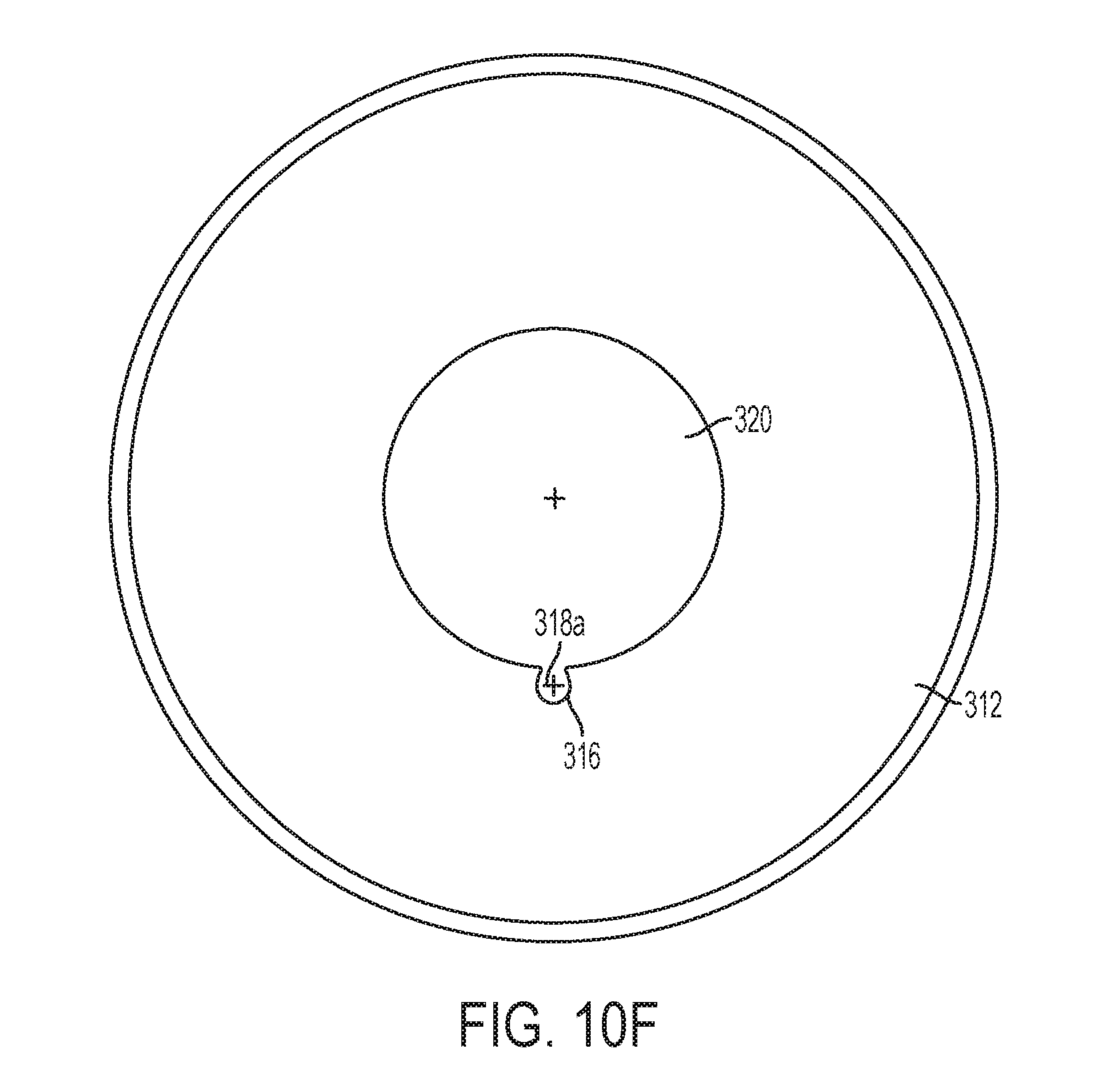
[0044] FIG. 10F is a top view of the cannula sleeve of FIG. 10D;
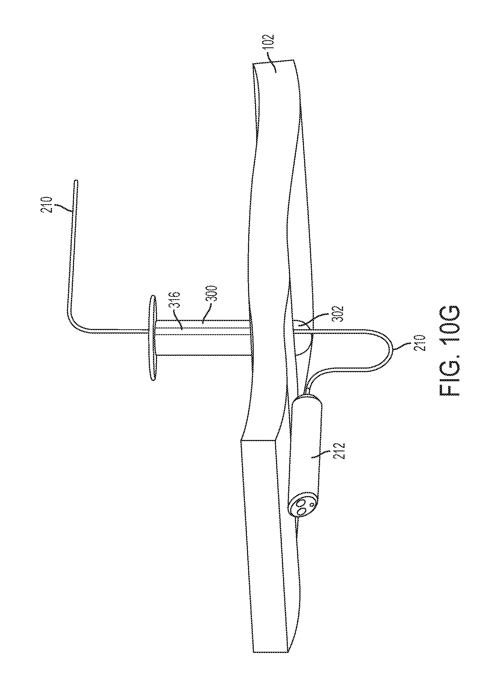
[0045] FIG. 10G is a perspective view of the cannula sleeve of FIG. 10D with a camera and tether;
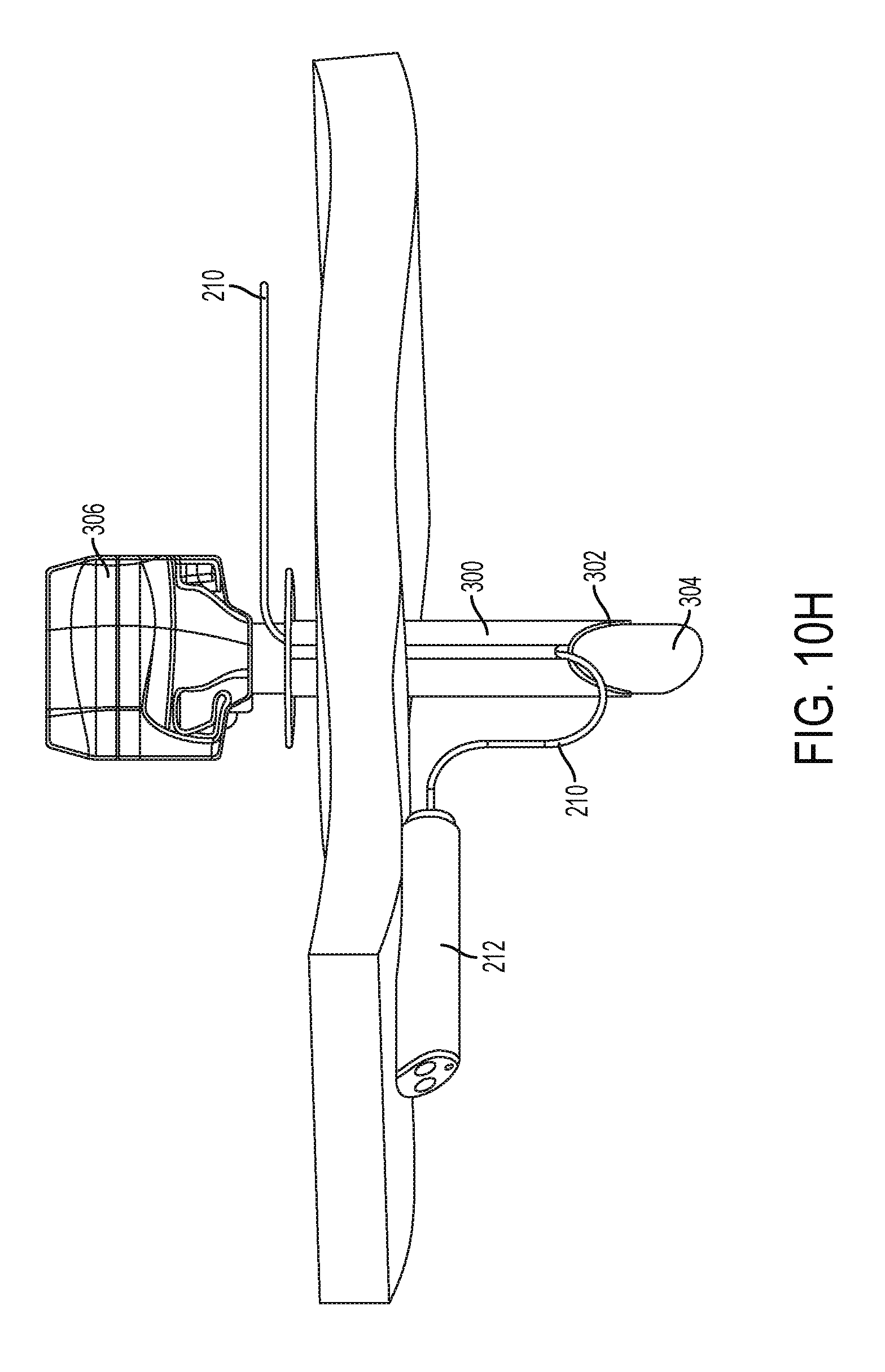
[0046] FIG. 10H is a perspective view of the trocar assembly of FIG. 10B with a camera and a tether; and
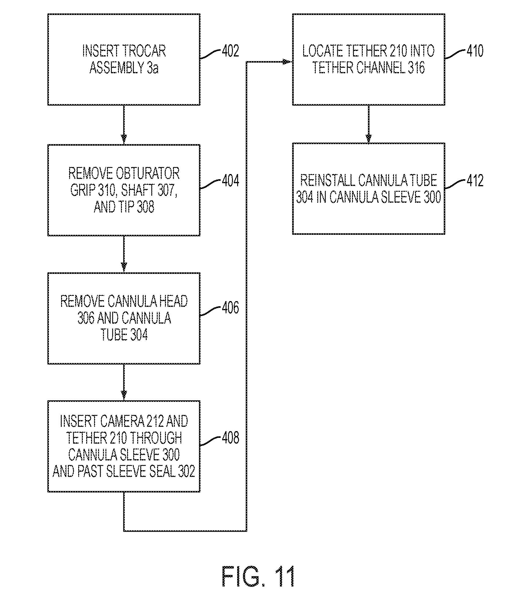
[0047] FIG. 11 is a flow chart of method steps for using the trocar assembly of FIG. 10A with a camera and tether.
[0048] Corresponding reference characters indicate corresponding parts throughout the several views. The exemplifications set out herein illustrate various embodiments of the invention, in one form, and such exemplifications are not to be construed as limiting the scope of the invention in any manner.
DETAILED DESCRIPTION OF THE INVENTION
[0049] Numerous specific details are set forth to provide a thorough understanding of the overall structure, function, manufacture, and use of the embodiments as described in the specification and illustrated in the accompanying drawings. It will be understood by those skilled in the art, however, that the embodiments may be practiced without such specific details. In other instances, well-known operations, components, and elements have not been described in detail so as not to obscure the embodiments described in the specification. Those of ordinary skill in the art will understand that the embodiments described and illustrated herein are non-limiting examples, and thus it can be appreciated that the specific structural and functional details disclosed herein may be representative and do not necessarily limit the scope of the embodiments, the scope of which is defined solely by the appended claims.
[0050] In describing and claiming the present invention, the following terminology will be used in accordance with the definitions set out below.
[0051] Reference throughout the specification to "various embodiments," "some embodiments," "one embodiment," or "an embodiment", or the like, means that a particular feature, structure, or characteristic described in connection with the embodiment is included in at least one embodiment. Thus, appearances of the phrases "in various embodiments," "in some embodiments," "in one embodiment," or "in an embodiment", or the like, in places throughout the specification are not necessarily all referring to the same embodiment. Furthermore, the particular features, structures, or characteristics may be combined in any suitable manner in one or more embodiments. Thus, the particular features, structures, or characteristics illustrated or described in connection with one embodiment may be combined, in whole or in part, with the features structures, or characteristics of one or more other embodiments without limitation.
[0052] It will be appreciated that the terms "proximal" and "distal" may be used throughout the specification with reference to a clinician manipulating one end of an instrument used to treat a patient. The term "proximal" refers to the portion of the instrument closest to the clinician and the term "distal" refers to the portion located farthest from the clinician. It will be further appreciated that for conciseness and clarity, spatial terms such as "vertical," "horizontal," "up," and "down" may be used herein with respect to the illustrated embodiments. However, surgical instruments may be used in many orientations and positions, and these terms are not intended to be limiting and absolute.
[0053] As used herein, the term "biocompatible" includes any material that is compatible with the living tissues and system(s) of a patient by not being substantially toxic or injurious and not known to cause immunological rejection. "Biocompatibility" includes the tendency of a material to be biocompatible.
[0054] As used herein, the term "patient" refers to any human or animal on which a suturing procedure may be performed. As used herein, the term "internal site" of a patient means a lumen, body cavity or other location in a patient's body including, without limitation, sites accessible through natural orifices or through incisions.
[0055] FIG. 1A is a perspective view of a surgical trocar assembly 100, such as the trocar assembly described in U.S. Pat. No. 5,817,061, the relevant portions of which are incorporated by reference, modified to incorporate an embodiment of the present invention, passing through tissue 102 of an animal, such as, for example, a human. The surgical trocar assembly 100 includes a cannula tube 104 attached to a lower cannula housing 106. An upper cannula housing 108 is mounted on top of the lower cannula housing 106 and is held in place by thumb screws 114a and 114b. A cannula head 110 is attached to the top of the upper cannula housing 108. The cannula head 110 may be permanently attached to the upper cannula housing 108, for example, by glue, epoxy, or other bonding agents, or by welding, such as ultrasonic welding. Alternatively, the cannula head 110 may be removably attached to the upper cannula housing 108, for example, by screws, bolts, clips, or the like. The cannula tube 104 is hollow, and the lower cannula housing 106, upper cannula housing 108, and cannula head 110 each include an aperture aligned with the hollow cannula tube 104 such that an obturator shaft 115 may pass therethrough. The obturator shaft 115 may terminate at a distal end with an obturator tip 116. The obturator shaft 115 is attached at its proximal end to an obturator grip 112. The obturator grip 112 may be attachable to the cannula head 110, for example, by a spring-loaded clip (not shown), such that the trocar assembly 100 may be manipulated as a whole. In FIG. 1A, a substantial portion of the cannula tube 104, and the obturator shaft 115, and the obturator tip 116 have penetrated the tissue 102 and have passed into an interior body cavity 103, such as, for example, an abdominal cavity. The lower cannula housing 106, upper cannula housing 108, cannula head 110, and obturator grip 112 remain in an exterior space 105. When the trocar assembly 100 is positioned as shown in FIG. 1A, the obturator shaft 115 may be removed from the cannula tube 104. FIG. 1B is a perspective view of the surgical trocar subassembly 100 with the obturator shaft 115 and obturator grip 112 so removed.
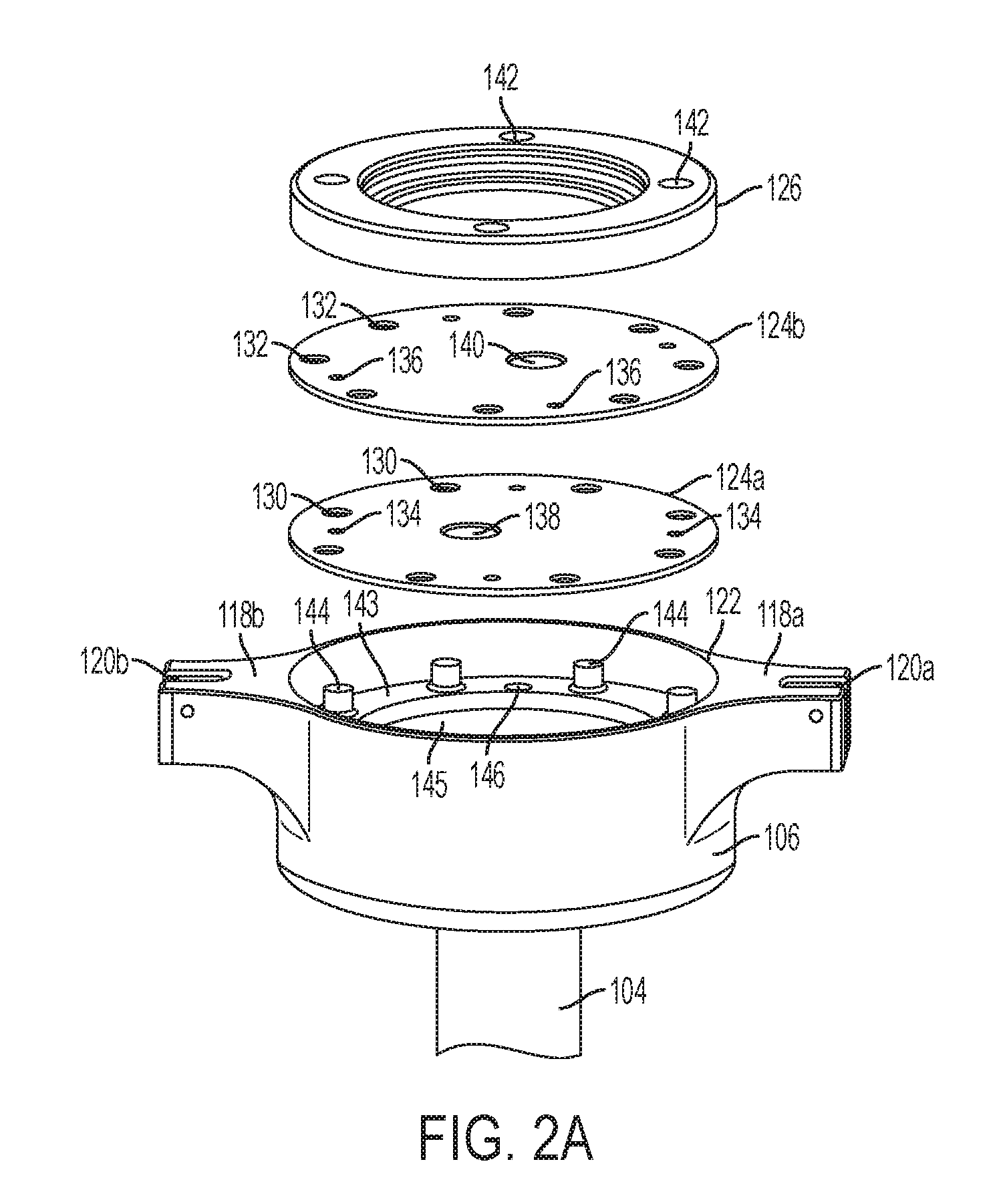
[0056] FIG. 2A is a perspective exploded view of the lower cannula housing 106 and sealing membranes 124a and 124b disposed therein. The lower cannula housing 106 may be hollow, including a proximal opening 122 that communicates with the upper cannula housing 108 (not shown in FIG. 2A) and a passage 145 that communicates with the hollow cannula tube 104. An engagement surface 143 in the passage 145 includes several engagement members, such as pins, clips, or anchors 144. For example, the engagement members 144 may be posts, such as, for example, cylindrical posts around the periphery of the engagement surface 143. A plurality of membranes 124a and 124b (in the embodiment shown in FIG. 2A, two membranes) may be placed in the passage and secured to the engagement surface 143. The membranes at least partially block fluid communication between the proximal opening 122 and the passage 145. Each membrane preferably may be made of a compliant material, such as, for example, silicone, latex, or rubber. Membrane 124a may include engagement members 130 on its periphery that compliment the engagement members 144 on the engagement surface. Membrane 124b may include engagement members 132 on its periphery that compliment the engagement members 144 on the engagement surface. For example, each of the engagement members 130, 132 may comprise a series of holes arranged on the periphery of respective membranes 124a and 124b. The engagement members 130, 132 on respective membranes 124a and 124b align with the engagement members 144 on the engagement surface 143, and placement of the engagement members 130, 132 over the anchors result in each membrane 124a and 124b being aligned in a fixed facing relationship relative to remaining membranes. Placement of the engagement members 130, 132 over the engagement members 144 also may result in the membranes 124a and 124b being stretched. A retaining ring 126 may be placed on top of the membranes 124a and 124b to hold the membranes 124a and 124b in place. The retaining ring 126 may include holes 142 sized to accommodate screws or other fasteners (not shown). The fasteners also may pass through holes 136 in membrane 124b and holes 134 in membrane 124a to anchor in holes 146 in the engagement surface 143. Membrane 124a includes an aperture 138 and membrane 124b includes an aperture 140. When the membranes 124a and 124b are installed in the lower cannula housing 106, the apertures 138 and 140 preferably are not aligned, i.e., the apertures 138 and 140 do not overlap. For example, the apertures 138, 140 may be disposed proximate to centers of the membranes 124a and 124b, but each membrane's aperture is offset from the membrane's center such that the aperture 138 of the first membrane 124a does not overlap with the aperture 140 of the second membrane 124b.
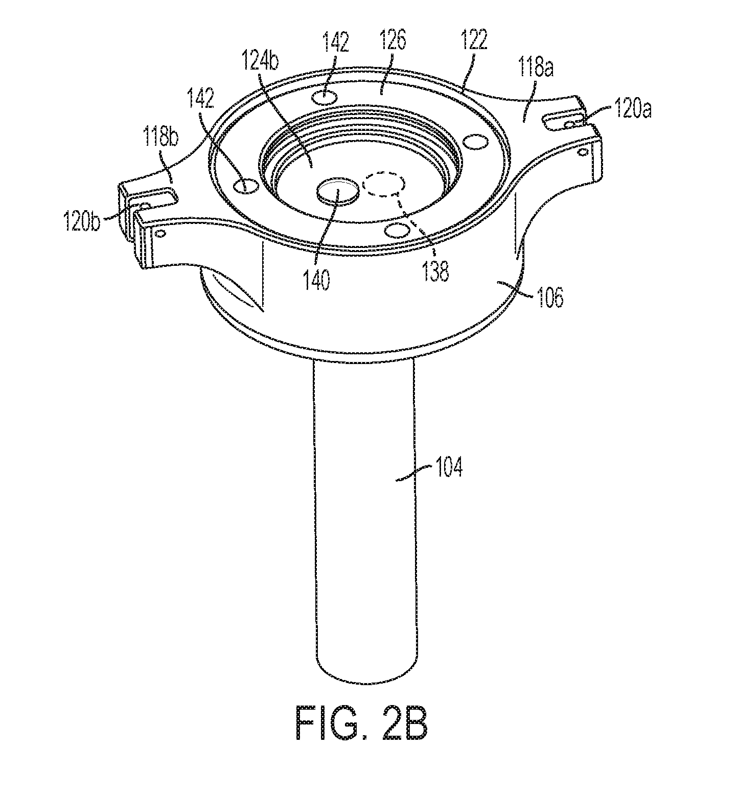
[0057] FIGS. 2B and 2C are perspective and top views, respectively, of the lower cannula housing of FIG. 2A showing the membranes 124a and 124b and the retaining ring 126 installed. In the installed configuration, the membranes 124a and 124b block the passage 145, and the apertures 138 and 140 in membranes 124a and 124b do not overlap. The lack of an overlap between apertures 138 and 140 provides a torturous path for gases or fluids between the passage 145 and the proximal opening 122 in the lower cannula housing 106. To escape from the cannula tube 104 to the proximal opening 122 in the lower cannula housing 106, gas (generally, an insufflation gas, such as carbon dioxide) must pass through the aperture 138 in the first membrane 124a (which is pressed against the second membrane 124b), travel through the space between the two sandwiched membranes 124a and 124b, and then pass through the aperture 140 in the second membrane. Because the membranes 124a and 124b are stacked on top of each other and because each membrane 124a and 124b is stretched across the anchors 144, the membranes are in close contact with each other. Also, the differential pressure of the insufflation gases in the cannula tube 104 over atmospheric pressure at the proximal opening 122 in the lower cannula housing 106 presses membrane 124a into membrane 124b, thereby maintaining membrane 124a in contact with membrane 124b. This tight path between the membranes 124a and 124b through which the insufflation gases must pass to get from aperture 138 to aperture 140 is a torturous path that inhibits leakage of the insufflation gases.
[0058] The membranes 124a and 124b preferably may be made of compliant materials, described above, which enable endoscopic tools to be pushed through the apertures 138, 140 without requiring alignment of a distal end of a tool with the apertures 138, 140. For example, if the obturator shaft 115 and obturator tip 116 are reinserted into the cannula tube, they must pass through the membranes 124a and 124b. The obturator tip 116 pressing on the membranes 124a and 124b will cause the membranes 124a and 124b to stretch, and the stretching will cause the apertures 138, 140 to shift towards the obturator tip 116. Thus, by pushing the obturator tip 116 into the membranes 124a and 124b, the apertures 138, 140 in the membranes 124a and 124b automatically align with the obturator tip 116, thereby enabling the obturator tip 116 and the obturator shaft 115 to pass therethrough.
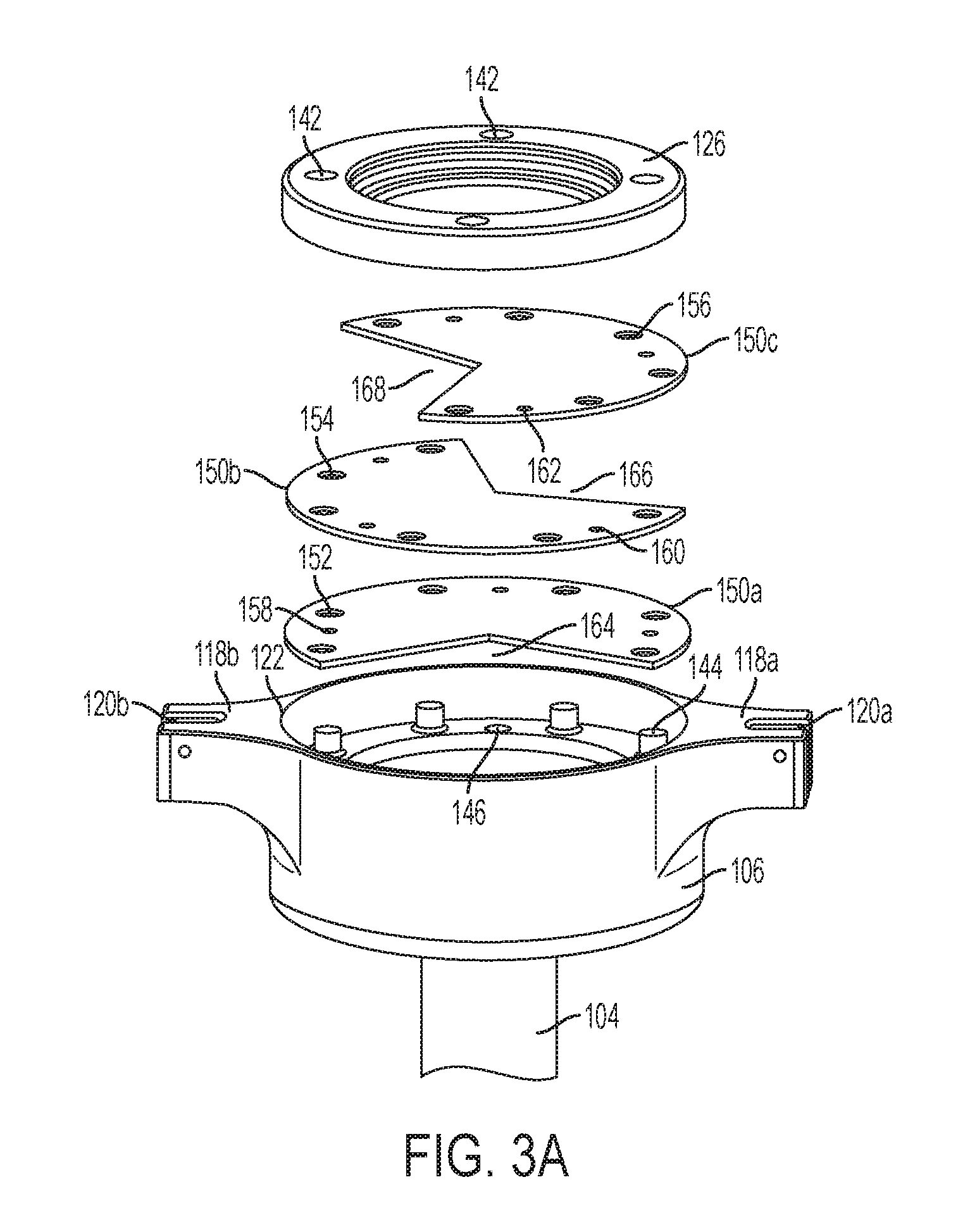
[0059] FIG. 3A is a perspective exploded view of a second embodiment in which there are more than two, for example, three membranes 150a-c. In certain embodiments, such as that shown in FIG. 3A, the membranes have wedge-shaped apertures 164, 166, and 168, respectively. FIG. 3B is a perspective view of the embodiment in FIG. 3A in an installed configuration. Each wedge-shaped aperture 164, 166, 168 does not overlap apertures of adjacent layers and may not overlap the apertures 164, 166, 168 of any other membrane layer. Thus, insufflation gases from the cannula tube 104 must pass between the first membrane 150a and the second membrane 150b, and then between the second membrane 150b and the third membrane 150 to escape to the proximal opening 122 in the lower cannula housing 106 through the apertures 164, 166, and 168. Furthermore, the wedge-shaped apertures 164, 166, 168 preferably do not extend over the center point of the respective membranes 150a-c so that the wedge-shaped apertures 164, 166, 168 do not overlap in any way to form a direct path through which insufflation gases may escape.
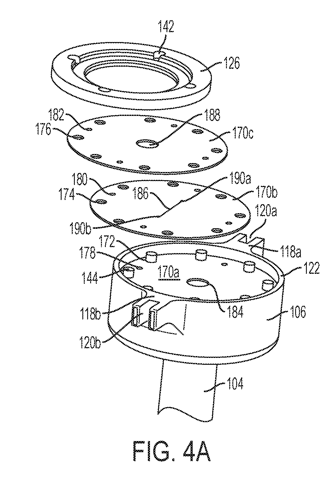
[0060] FIG. 4A is a perspective partially-exploded view of another embodiment in which there are three membranes 170a (shown installed), 170b, and 170c. Membrane 170a has a circular aperture 184 proximate to its center and membrane 170c also has a circular aperture 188 proximate to its middle. Membrane 170b has a slit 186 as an aperture. For clarity, the slit 186 is shown with a gap between its sides. However, the slit may be formed by cutting a line in the membrane 170b, removing no membrane material or a negligible amount of membrane material such that the slit 186 has no gap when the membrane 170b is not deformed. Additionally, the slit 186 may include relief cuts 190a and 190b at its ends. The relief cuts 190a,b provide for stress relief at ends of the slit 186 when the slit is stretched and enables the slit 186 to stretch to a larger shape without tearing the membrane. FIG. 4D shows a slit 186 without relief cuts 190a and 190b stretched open, e.g., by an endoscopic tool. The size of the opening of slit 186 is limited by the ends. FIG. 4E shows the slit 186 with relief cuts 190a and 190b at end. The relief cuts 190a and 190b enable the slit 186 to open to a larger size.
[0061] In certain embodiments, such as that shown in FIG. 4B, the apertures 184, 186, and 188 may be arranged on their respective membranes 170a, 170b, and 170c such that the apertures 184, 186, and 188 overlap when the membranes 170a, 170b, and 170c are stacked in the lower cannula housing 106. In certain embodiments, such as that shown in FIG. 4C, the apertures 184, 186, and 188 may be arranged on their respective membranes 170a, 170b, and 170c such that the apertures do not overlap when the membranes 170a, 170b, and 170c are stacked in the lower cannula housing 106. In certain embodiments, the apertures 184, 186, and 188 may be arranged on their respective membranes 170a, 170b, and 170c such that the apertures partially overlap when the membranes 170a, 170b, and 170c are stacked in the lower cannula housing 106. As described above, differential pressure of the insufflation gas over atmospheric pressure presses the membranes against each other. The slit 186 in membrane 170b is assisted in remaining closed by being sandwiched between membranes 170a and 170c.
[0062] FIG. 5 shows a cannula tube 104 inserted through tissue 102 with membranes, such as any of the membranes described above in FIGS. 2A-4C, installed in the lower cannula housing 106. FIGS. 6A-B show a magnetic camera 212 placed in the abdominal cavity 103 through the lower cannula housing 106 and the cannula tube 104. The camera 212 may be attached to a tether 210. The tether includes one or more strands, for example, one strand may carry power to the camera, another strand carries image data from the camera, and another strand possibly carries gases or fluids to ports attached to the camera. The tether 210 runs from the camera 212 through the cannula tube 104 and the lower cannula housing 106. The tether 210 also passes through apertures 214 in membranes 212, such as, for example, the membranes 124a-b, 150a-c, and 170a-c described above. FIGS. 5 and 6A-B also show thumb screws 114a and 114b mounted on respective posts 200a and 200b. The posts 200a and 200b include threaded ends (not shown) onto which the thumb screws 114a and 114b are mounted. The posts 200a and 200b are connected to respective buttresses 118a and 118b by pins 202a and 202b. When the thumb screws are in a loose position, the thumb screws 114a and 114b may be rotated about pins 202a and 202b in the direction of arrows labeled "A" and "A'" about axes of rotation "B-B" and "B'-B", respectively, in FIG. 5, to be out of the way of the upper cannula housing 108 being placed on top of the lower cannula housing 106. After the upper cannula housing 108 is placed on top of the lower cannula housing 106, the thumb screws 114a and 114b may be rotated in directions opposite to arrows "A" and "A'". Then, the thumb screws 114a and 114b may be turned on their respective posts 200a and 200b such the thumb screws 114a and 114b clamp down on respective buttresses 109a and 109b of the upper cannula housing 108.
[0063] FIG. 7 shows the upper cannula housing 108 and the cannula head 110 mounted on top of the lower cannula housing 106. The upper cannula housing 108 includes a port housing 216 that includes one or more ports 218a and 218b. The ports 218a and 218b provide a path for the tether 210 to exit the cannula tube 104 and the cannula housing 106, 108. The number of ports may correspond to the number of strands making up the tether 210, wherein each strand may pass through a distinct port. The ports 218a and 218b are sized to accommodate the tether 210. The ports 218a and 218b may be sized such that the tether 210 fits snugly therethrough or the ports 218a and 218b may include an additional gasket through which the tether 210 runs. For example, the gasket may be a compliant membrane that covers a port, such as, for example, port 218a, and the compliant membrane may include an aperture through which the tether may pass. The gasket also may be an o-ring positioned within a port, such as, for example, port 218a, that snugly fits with a tether passing therethrough. The snug fit of the gasket further retards leakage of insufflation gases. When the tether 210 is drawn through the ports 218a and 218b, the tether 210 is biased to a side of the cannula tube 104, i.e., away from the center of the cannula tube 104 nearest to the ports 218a and 218b. Consequently, the tether 210 is out of the way of any additional endoscopic tools passing through the cannula tube 104.
[0064] FIG. 8 shows another embodiment of a cannula tube 220 having a slot 226 defining an opening running along the length of the cannula tube 220, generally, and preferably substantially parallel to its longitudinal axis. The slot 226 enables the tether 220 to exit the cannula tube 220 at a more proximal point 224 than the distal end 222 of the cannula tube 220. Removing the tether 210 from the cannula tube 220 at the more proximal point 224 minimizes interactions between the tether 210 and other endoscopic devices (not shown) in the cannula tube 220, which may cause tugging on the tether 210 (and inadvertent movement of the camera 212) or cause inadvertent movement of endoscopic tools.
[0065] In various embodiments, the cannula housing may be structured for movement to reposition the openings to the passage. For example, FIGS. 9A-9I show an embodiment of a cannula including a bracket 230 and a rotating housing 233. The rotating housing 233 includes a passage 276 (FIG. 9B) that is in fluid communication with a bracket opening 270 (FIG. 9D) in the bracket 230. The rotating housing 233 may also include a first opening 272 and a second opening 274, each of which can be in fluid communication with the passage 276. The first opening 272 may include first membranes 236 and respective apertures 238. The second opening 274 may include second membranes 244 and respective apertures 246. In certain embodiments, the first membranes 236 and the second membranes 244 can include a plurality of membranes, similar to the membranes shown in FIGS. 2A-4E. The apertures 238 and 246 can be in fluid communication with the passage 276. The bracket 230 may be coupled to a hollow cannula tube 220 and the bracket opening 270 may be in fluid communication with the cannula tube 220. The cannula tube 220 may include a longitudinal slot 226. Alternatively, the cannula tube 220 can be similar to those shown above with respect to FIGS. 1A-7, for example. The rotating housing 233 is rotationally coupled to the cannula bracket 230 by bearings 240. The bearings 240 may be any type of bearings, such as ball bearings, planar bearings, and/or journal bearings, for example.
[0066] A seal housing 260 can be positioned intermediate the bracket 230 and the rotating housing 233. Referring particularly to FIG. 9E, the seal housing 260 can include an interior surface 262 that includes a slightly larger profile than an exterior cylindrical surface of the rotating housing 233. The seal housing 260 also includes a seal passage 266 in fluid communication with the bracket opening 270 and the passage 276 in the rotating housing 233. When assembled, the close fit between the rotating housing 233 and the seal housing 260 provides a seal for the passage 276 and/or the first and second openings 272 and 274 that can inhibit the escape of gases. For example, in use, insufflation gases in a patient's abdomen can be inhibited from escaping through the cannula tube 220 and the passage 276 by the interior surface 262 of the seal housing 260. The interior surface 262 of the seal housing 260 can also inhibit the escape of insufflation gases through the first opening 272 when the rotating housing 233 is rotated such that the first opening 272 is aligned with a portion of the interior surface 262, an example of which is illustrated in FIG. 9H. The interior surface 262 of the seal housing 260 can also inhibit the escape of insufflation gases through the second opening 274 when the rotating housing 233 is rotated such that the second opening 274 is aligned with a portion of the interior surface 262, an example of which is illustrated in FIG. 9D.
[0067] Referring to FIG. 9H, the aperture 238 is shown as a slit that is aligned with a slit 264 in the seal housing 260. The slit 264 in the seal housing 260 can accommodate the tether 210 of the camera. In certain embodiments, the aperture 238 may not be aligned with the slit 264 in the seal housing 260 to further inhibit the escape of insufflation gases. For example, if the aperture 238 is a slit, such as the slit shown in FIG. 9H, then the aperture 238 may be rotated ninety degrees relative to the slit 264 in the seal housing 260. As another example, if the aperture 238 is a circular hole, then the hole may be offset from the slit 264 in the seal housing 260.
[0068] Referring to FIG. 9C, in use, the rotating housing 233 can be oriented such that the first opening 272 is aligned with a longitudinal axis of the cannula tube 220 and the bracket opening 270. An obturator shaft and tip, such as obturator shaft 115 and obturator tip 116, shown in FIG. 1A, may be inserted through the first opening 272 and the apertures 238 in the membranes 236 therein such that the obturator top 116 protrudes from the distal end of the cannula tube 220. An obturator grip, such as obturator grip 112, may be attached to a proximal end of the obturator shaft 115, and may couple to the cannula housing 233 and/or the bracket 230. The obturator tip 116 may guide the cannula tube 220 through an otomy in a patient. Then, the obturator shaft 115 and obturator tip 116 can be removed from the cannula tube 220, bracket 230, and rotating housing 233. As illustrated in FIG. 9I, the close spacing between the seal housing 260 and the rotating housing 233 can inhibit the escape of insufflation gases through the passage 276 in the rotating housing. A camera can be passed through the apertures 238 in the first membranes 236 and through the cannula tube 220 and into a body cavity. Referring to FIGS. 9C-9F, a tether 210 of the camera is shown passing through the first apertures 238 and out through the cannula tube 220.
[0069] Referring to FIG. 9G, after the camera is positioned in the body cavity and the tether 210 passes through the cannula tube 220 and the first opening 272 in the rotating housing 233, the rotating housing 233 can be rotated in the direction of arrow B. In the rotated configuration, the first opening 272 is not aligned with the longitudinal axis of the cannula tube 220. As a result, the tether 210 is biased toward a perimeter of the cannula tube 220. If the cannula tube 220 includes a longitudinal slot 226, then it can be advantageous for the tether 210 to be biased toward a side of the cannula tube 220 on which the longitudinal slot 226 is located. With the tether 210 biased towards the perimeter of the cannula tube 220, additional surgical instruments can be inserted through the apertures 246 in the second membranes 244 and the cannula tube 220 while minimizing interference between the tether 210 and the surgical instrument. Any interference can cause tugging of the tether, which may cause undesired movement of the camera in the patient. Any interference can also cause unwanted movement of the surgical instrument. In the rotated configuration, the first opening 272 is adjacent to the interior surface 262 of the seal housing 260. The slit 264 or similar opening in the seal housing 260 can accommodate the tether 210 of the camera as shown in FIGS. 9G and 9H.
[0070] In various embodiments, a cannula sleeve may be provided for enhanced sealing. Referring to FIG. 10A, a perspective view of another embodiment of a trocar assembly 301 passing through a cannula sleeve is shown. The trocar assembly 301 includes a cannula head 306 attached to a cannula tube 304. An obturator shaft 307 and obturator tip 308 are attached to an obturator grip 310, and the obturator shaft 307 and obturator grip 308 pass through the cannula head 306 and cannula tube 304. A cannula sleeve 300 surrounds or encases the cannula tube 304. The cannula sleeve 300 includes a seal 302 at its distal end. When the trocar assembly 301 penetrates tissue 102, the cannula sleeve 300 also penetrates the tissue 102.
[0071] FIG. 10D shows the cannula sleeve 300 alone. The cannula sleeve 300 includes a sleeve seal 302 at its distal end. In FIG. 10D, the sleeve seal 302 is shown in its open configuration. The sleeve seal 302 preferably is biased in a closed position (as shown in FIG. 10E). The sleeve seal 302 may be a duckbill seal, a clamshell seal, or any other type of seal. The cannula sleeve 300 generally comprises a substantially rigid or semi-rigid material, such as, for example, plastic or stainless steel. The sleeve seal 302 comprises a compliant material, such as, for example, silicone or rubber. The sleeve seal 302 may be attached to the cannula sleeve 300 by, for example, overmolding, adhesives, fasteners, welding, or the like. The cannula sleeve 300 may include a sleeve flange 312. The sleeve flange 312 provides a surface that can stops the cannula sleeve 300 from accidentally passing completely through an otomy in tissue. The cannula sleeve 300 also includes a tether channel 316. As shown in FIGS. 10D and 10G, the tether channel 316 may be outside of the periphery of the cannula tube 300 but also is in fluid communication with the hollow interior of the cannula tube 300. The tether channel 316 may include an open end 318a at its proximal end and an open end 318b at its distal end. The tether channel 316 and the open ends 318a and 318b can receive a camera tether, enabling the camera tether to pass through the cannula sleeve 300 without intruding on the hollow interior of the cannula tube 300. The open end 318b at the distal end of the cannula tube 300 also enables a camera tether to bypass the sleeve seal 302. As shown in FIG. 10E, when the sleeve seal 302 is closed, the hollow interior of the cannula tube 300 substantially is not in fluid communication with a body cavity into which it is inserted. The open end 318 is outside of the sleeve seal 302 and enables the camera tether to bypass the sleeve seal 302.
[0072] In use, after the obturator shaft 307 and obturator tip 308, cannula tube 304, and sleeve seal 300 have been inserted through tissue 102, the obturator tip 308 and shaft 307 may be removed, as shown in FIG. 10B. The cannula tube 304 still extends through the cannula sleeve 300, and the sleeve seal 302 therefore remains open.
[0073] In FIG. 10C, the cannula tube 304 has been partially withdrawn from the tissue 102 and from the cannula sleeve 300. The cannula sleeve 300 remains inserted in the body cavity through the tissue 102. Because the cannula tube 304 has been withdrawn from the distal end of the cannula sleeve 300, the sleeve seal 302 is able to close. The closed sleeve seal 302 inhibits the escape of insufflation gases. As described above, the sleeve seal 302 may be biased in a closed position such that it closes in the absence of the cannula tube 304 or other endoscopic device passing through the cannula tube 304. Because the cannula sleeve 300 is made of a rigid or semi-rigid material, it maintains its shape (in other words, the cannula sleeve 300 does not collapse) when the cannula tube 304 is removed.
[0074] FIG. 10H shows the cannula sleeve 300 with the camera 212 inserted therethrough. In addition, the cannula tube 304 has been reinserted into the cannula sleeve 300. Because the tether 210 is in the tether channel 316 outside of the passage 320 in the cannula sleeve 300, the cannula tube 304 can pass through the passage 320, and the cannula tube 304 does not pull on the tether 210.
[0075] FIG. 11 shows the steps performed by a surgeon to insert and use the trocar assembly 301 shown in FIGS. 10A-10H. In step 402, the surgeon inserts the trocar assembly 301 through the patient's tissue 102. After the trocar assembly 301 is inserted and properly positioned, in step 404, the obturator grip 310, shaft 307, and tip 308 are removed. Then, in step 406, the cannula head 306 and tube 304 are removed, leaving the cannula sleeve 300. Alternatively, steps 404 and 406 may be combined such that the obturator 310 and cannula 304 are removed from the cannula sleeve 300 simultaneously. In step 408, the surgeon inserts the camera 212 into the passage 320 of the cannula sleeve 300. The surgeon pushes the camera 212 past the sleeve seal 302 so that the camera 212 and a portion of the camera's tether 210 are in the interior body cavity 103. Then, in step 410, the surgeon locates the portion of the tether 210 passing through the cannula sleeve 300 into the tether channel 316. Then, in step 412, the surgeon reinserts the cannula tube 304 or another endoscopic surgical instrument into the cannula sleeve 300.
[0076] While the present invention has been illustrated by description of several embodiments and while the illustrative embodiments have been described in considerable detail, it is not the intention of the applicant to restrict or in any way limit the scope of the appended claims to such detail. Additional advantages and modifications may readily appear to those skilled in the art.
[0077] Endoscopic minimally invasive surgical and diagnostic medical procedures are used to evaluate and treat internal organs by inserting a small tube into the body. The endoscope may have a rigid or a flexible tube. A flexible endoscope may be introduced either through a natural body opening (e.g., mouth, nose, anus, and/or vagina) or via a trocar through a relatively small--keyhole--incision incisions (usually 0.5-2.5 cm). The endoscope can be used to observe surface conditions of internal organs, including abnormal or diseased tissue such as lesions and other surface conditions and capture images for visual inspection and photography. The endoscope may be adapted and configured with working channels for introducing medical instruments to the treatment region for taking biopsies, retrieving foreign objects, and/or performing surgical procedures.
[0078] All materials used that are in contact with a patient are preferably made of biocompatible materials.
[0079] Preferably, the various embodiments of the devices described herein will be processed before surgery. First, a new or used instrument is obtained and if necessary cleaned. The instrument can then be sterilized. In one sterilization technique, the instrument is placed in a closed and sealed container, such as a plastic or TYVEK.RTM. bag. The container and instrument are then placed in a field of radiation that can penetrate the container, such as gamma radiation, x-rays, or high-energy electrons. The radiation kills bacteria on the instrument and in the container. The sterilized instrument can then be stored in the sterile container. The sealed container keeps the instrument sterile until it is opened in the medical facility. Other sterilization techniques can be done by any number of ways known to those skilled in the art including beta or gamma radiation, ethylene oxide, and/or steam.
[0080] Although the various embodiments of the devices have been described herein in connection with certain disclosed embodiments, many modifications and variations to those embodiments may be implemented. For example, different types of end effectors may be employed. Also, where materials are disclosed for certain components, other materials may be used. The foregoing description and following claims are intended to cover all such modification and variations.
[0081] Any patent, publication, or other disclosure material, in whole or in part, that is said to be incorporated by reference herein is incorporated herein only to the extent that the incorporated materials does not conflict with existing definitions, statements, or other disclosure material set forth in this disclosure. As such, and to the extent necessary, the disclosure as explicitly set forth herein supersedes any conflicting material incorporated herein by reference. Any material, or portion thereof, that is said to be incorporated by reference herein, but which conflicts with existing definitions, statements, or other disclosure material set forth herein will only be incorporated to the extent that no conflict arises between that incorporated material and the existing disclosure material.
* * * * *
D00000
D00001
D00002
D00003
D00004
D00005
D00006
D00007
D00008
D00009
D00010
D00011
D00012
D00013

D00014

D00015
D00016
D00017
D00018

D00019

D00020
D00021

D00022

D00023

D00024
D00025

D00026

D00027
D00028
D00029
D00030
D00031
D00032
D00033
XML
uspto.report is an independent third-party trademark research tool that is not affiliated, endorsed, or sponsored by the United States Patent and Trademark Office (USPTO) or any other governmental organization. The information provided by uspto.report is based on publicly available data at the time of writing and is intended for informational purposes only.
While we strive to provide accurate and up-to-date information, we do not guarantee the accuracy, completeness, reliability, or suitability of the information displayed on this site. The use of this site is at your own risk. Any reliance you place on such information is therefore strictly at your own risk.
All official trademark data, including owner information, should be verified by visiting the official USPTO website at www.uspto.gov. This site is not intended to replace professional legal advice and should not be used as a substitute for consulting with a legal professional who is knowledgeable about trademark law.