Ligation Clip With Retention Features
Thomas; Justin ; et al.
U.S. patent application number 16/261803 was filed with the patent office on 2019-10-24 for ligation clip with retention features. The applicant listed for this patent is Covidien LP. Invention is credited to Saumya Banerjee, Eric Brown, Matthew A. Dinino, Gregory R. Morck, Roy J. Pilletere, Justin Thomas.
| Application Number | 20190321047 16/261803 |
| Document ID | / |
| Family ID | 68236154 |
| Filed Date | 2019-10-24 |


| United States Patent Application | 20190321047 |
| Kind Code | A1 |
| Thomas; Justin ; et al. | October 24, 2019 |
LIGATION CLIP WITH RETENTION FEATURES
Abstract
A surgical ligation clip includes a first jaw and a second jaw pivotably coupled to the first jaw. The first and second jaws define first and second clamping surfaces, respectively, and have longitudinal ribs and transverse ribs that define first and second recesses on the first and second clamping surfaces. The second jaw is pivotable in relation to the first jaw from an open position to a clamped position to clamp tissue between the first and second clamping surfaces. In the clamped position, each of the longitudinal ribs on the first jaw is axially aligned with one of the longitudinal ribs on the second jaw and each of the transverse ribs on the first jaw is axially offset from each of the transverse ribs on the second jaw.
| Inventors: | Thomas; Justin; (New Haven, CT) ; Brown; Eric; (Haddam, CT) ; Morck; Gregory R.; (Middletown, CT) ; Pilletere; Roy J.; (North Haven, CT) ; Banerjee; Saumya; (Hamden, CT) ; Dinino; Matthew A.; (Newington, CT) | ||||||||||
| Applicant: |
|
||||||||||
|---|---|---|---|---|---|---|---|---|---|---|---|
| Family ID: | 68236154 | ||||||||||
| Appl. No.: | 16/261803 | ||||||||||
| Filed: | January 30, 2019 |
Related U.S. Patent Documents
| Application Number | Filing Date | Patent Number | ||
|---|---|---|---|---|
| 62661842 | Apr 24, 2018 | |||
| Current U.S. Class: | 1/1 |
| Current CPC Class: | A61B 17/122 20130101 |
| International Class: | A61B 17/122 20060101 A61B017/122 |
Claims
1. A ligation clip comprising: a first jaw defining a first clamping surface, the first clamping surface supporting first longitudinal ribs that extend along at least a portion of a length of the first clamping surface and first transverse ribs that extend across at least a portion of a width of the first clamping surface, the first longitudinal ribs and the first transverse ribs defining first recesses on the first clamping surface; and a second jaw pivotably supported in relation to the first jaw and defining a second clamping surface, the second clamping surface supporting second longitudinal ribs that extend along at least a portion of a length of the second clamping surface and second transverse ribs that extend across at least a portion of a width of the second clamping surface, the second longitudinal ribs and the second transverse ribs defining second recesses on the second clamping surface, the second jaw being pivotable in relation to the first jaw from an open position to a clamped position to clamp tissue between the first and second clamping surfaces, wherein in the clamped position, each of the first longitudinal ribs is aligned with one of the second longitudinal ribs and each of the first transverse ribs is axially offset from each of the second transverse ribs.
2. The ligation clip of claim 1, wherein the ligation clip defines a longitudinal axis and the first and second longitudinal ribs each include a central rib that extends along the longitudinal axis and side ribs that extend along outer edges of the first and second clamping surfaces.
3. The ligation clip of claim 2, wherein each of the first and second transverse ribs are formed in groups of two, the groups being spaced from adjacent groups along each of the first and second clamping surfaces.
4. The ligation clip of claim 3, wherein each of the transverse ribs in each group of transverse ribs is spaced closer to the other transverse rib within the group of transverse ribs than to the transverse ribs in adjacent groups of transverse ribs.
5. The ligation clip of claim 2, wherein each of the longitudinal ribs is defined by a radiused side wall.
6. The ligation clip of claim 5 wherein each of the first and second transverse ribs is defined by a radiused side wall.
7. The ligation clip of claim 1, wherein the first jaw is secured to the second jaw by a living hinge.
8. The ligation clip of claim 1, wherein the ligation clip is formed of a polymeric material.
9. The ligation clip of claim 1, wherein the first and second jaws support bosses, the bosses being configured to engage a clip applier.
10. The ligation clip of claim 1, wherein the first jaw includes a first locking element and the second jaw includes a second locking element, the second locking element being movable into engagement with the first locking element as the ligation clip is moved towards the clamped position to retain the ligation clip in the clamped position.
11. The ligation clip of claim 1, wherein the second jaw includes a distal portion, the distal portion including spaced teeth that are configured to penetrate tissue.
12. The ligation clip of claim 10, wherein the second jaw includes a biasing member that is positioned to engage the first locking element in the clamped position to retain the first locking element in engagement with the second locking element.
13. The ligation clip of claim 12, wherein the first and second recesses are rectangular.
14. The ligation clip of claim 1, wherein each of the recesses has a bottom surface, the bottom surface being defined by the radiused side walls of the first and second longitudinal ribs.
Description
CROSS-REFERENCE TO RELATED APPLICATION
[0001] This application claims the benefit of and priority to U.S. Provisional Patent Application No. 62/661,842 filed Apr. 24, 2018, the entire disclosure of which is incorporated by reference herein.
BACKGROUND
1. Technical Description
[0002] The present disclosure is directed to ligation clips for sealing body vessels and, more particularly, to ligation clips that include clamping surfaces with tissue retention features for sealing body vessels.
2. Background of Related Art
[0003] Ligation clips are commonly used during a variety of surgical procedures to ligate tissue, e.g., a body vessel. Typically, ligation clips include first and second jaws that include clamping surfaces. The jaws are pivotably connected to each other at one end and are movable between open and clamped positions. When the ligation clip is applied to a portion of a body vessel, the body vessel is clamped between the clamping surfaces of the first and second jaws. After the ligation clip is applied to the body vessel, any movement of the ligation clip in relation to the body vessel may have a negative impact on the performance of the ligation clip.
[0004] A continuing need exists in the art for ligation clips that have clamping surfaces with improved retention characteristics to prevent movement of the ligation clip in relation to a body vessel after the ligation clip is applied to the body vessel.
SUMMARY
[0005] One aspect of the disclosure is directed to a ligation clip that includes a first jaw and a second jaw pivotably coupled to the first jaw. The first jaw defines a first clamping surface that supports first longitudinal ribs that extend along at least a portion of the length of the first clamping surface and first transverse ribs that extend across at least a portion of the width of the first clamping surface. The first longitudinal ribs and the first transverse ribs define first recesses on the first clamping surface. The second jaw defines a second clamping surface that supports second longitudinal ribs that extend along at least a portion of the length of the second clamping surface and second transverse ribs that extend across at least a portion of the width of the second clamping surface. The second longitudinal ribs and the second transverse ribs define second recesses on the second clamping surface. The second jaw is pivotable in relation to the first jaw from an open position to a clamped position to clamp tissue between the first and second clamping surfaces. In the clamped position, each of the first longitudinal ribs is aligned with one of the second longitudinal ribs and each of the first transverse ribs is axially offset from each of the second transverse ribs.
[0006] In embodiments, the ligation clip defines a longitudinal axis and the first and second longitudinal ribs each include a central rib that extends along the longitudinal axis and side ribs that extend along outer edges of the first and second clamping surfaces.
[0007] In some embodiments, each of the first and second transverse ribs are formed in groups of two, wherein each group of transverse ribs is spaced from adjacent groups along the respective first and clamping surfaces.
[0008] In certain embodiments, each of the transverse ribs in each group of transverse ribs is spaced closer to the other transverse rib within the group than to the transverse ribs in adjacent groups of transverse ribs.
[0009] In embodiments, each of the longitudinal ribs is defined by a radiused side wall.
[0010] In some embodiments, each of the first and second transverse ribs is defined by a radiused side wall.
[0011] In certain embodiments, the first jaw is secured to the second jaw by a living hinge.
[0012] In embodiments, the ligation clip is formed of a polymeric material.
[0013] In some embodiments, the first and second jaws support bosses that are configured to engage a clip applier.
[0014] In certain embodiments, the first jaw includes a first locking element and the second jaw includes a second locking element that is movable into engagement with the first locking element as the ligation clip is moved towards the clamped position to retain the ligation clip in the clamped position.
[0015] In embodiments, the second jaw includes a distal portion that has spaced teeth that are configured to penetrate tissue.
[0016] In some embodiments, the second jaw includes a biasing member that is positioned to engage the first locking element in the clamped position to retain the first locking element in engagement with the second locking element.
[0017] In certain embodiments, the first and second recesses are rectangular.
[0018] In embodiments, the recesses include a bottom surface, the bottom surface being defined by the radiused side walls of the first and second longitudinal ribs.
BRIEF DESCRIPTION OF THE DRAWINGS
[0019] Various exemplary embodiments of the presently disclosed ligation clip are described herein below with reference to the drawings, wherein:
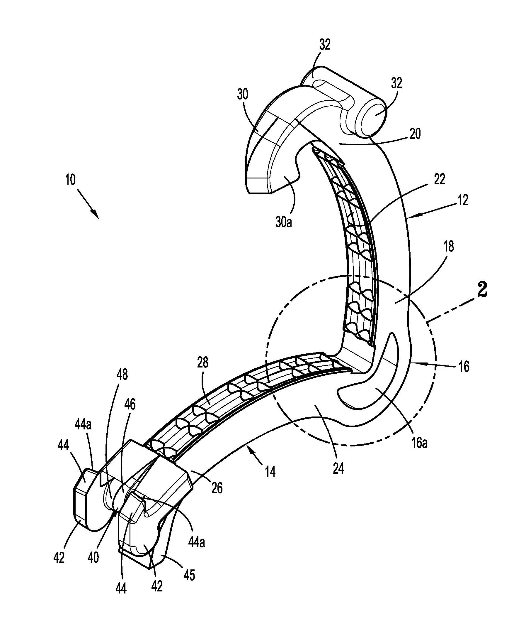
[0020] FIG. 1 is a side perspective view of an exemplary embodiment of the presently disclosed ligation clip in an open position;
[0021] FIG. 2 is an enlarged view of the indicated area of detail shown in FIG. 1;
[0022] FIG. 3 is a cross-sectional view taken along section line 3-3 of FIG. 2;
[0023] FIG. 4 is an enlarged view of the indicated area of detail shown in FIG. 3;
[0024] FIG. 5 is a side cross-sectional view of the ligation clip shown in FIG. 1 in the clamped position;
[0025] FIG. 6 is a cross-sectional view taken along section line 6-6 of FIG. 5;
[0026] FIG. 7 is a side view of the ligation clip shown in FIG. 1 placed about tissue in the open position; and
[0027] FIG. 8 side cross-sectional view of the ligation clip shown in FIG. 1 placed about tissue in the clamped position; and
[0028] FIG. 9 is a cross-sectional view taken along section line 9-9 of FIG. 8.
DETAILED DESCRIPTION OF EMBODIMENTS
[0029] The presently disclosed ligation clip will now be described in detail with reference to the drawings in which like reference numerals designate identical or corresponding elements in each of the several views. However, it is to be understood that the disclosed embodiments are merely exemplary of the disclosure and may be embodied in various forms. Well-known functions or constructions are not described in detail to avoid obscuring the present disclosure in unnecessary detail. Therefore, specific structural and functional details disclosed herein are not to be interpreted as limiting, but merely as a basis for the claims and as a representative basis for teaching one skilled in the art to variously employ the present disclosure in virtually any appropriately detailed structure.
[0030] In this description, the term "proximal" is used generally to refer to that portion of the device that is closer to a clinician, while the term "distal" is used generally to refer to that portion of the device that is farther from the clinician. In addition, the term "clinician" is used generally to refer to medical personnel including doctors, nurses, and support personnel. Further, the term "about" is used generally to mean plus or minus 10 percent of the disclosed parameter.
[0031] FIGS. 1-6 illustrate an exemplary embodiment of the presently disclosed ligation clip shown generally as 10. The ligation clip 10 defines a longitudinal axis "X" (FIG. 5) and includes a first jaw 12, a second jaw 14, and a hinge portion 16 coupling the first jaw 12 to the second jaw 14. The first jaw 12 is pivotable in relation to the second jaw 14 about the hinge portion 16 to move the ligation clip 10 between an open position (FIG. 1) and a clamped position (FIG. 5). In embodiments, the first and second jaws 12, 14 are curved along the longitudinal axis "X" of the ligation clip 10 although other jaw configurations are envisioned. The hinge portion 16 may be integrally formed with the first and second jaws 12, 14, e.g., a living hinge, and may define a crescent shaped through bore 16a to facilitate movement of the first jaw 12 in relation to the second jaw 14 between the open and clamped positions. The through bore 16a also allows for substantially complete closure of proximal portions of the first and second jaws 12, 14.
[0032] Referring to FIG. 1, the first jaw 12 includes a proximal portion 18, a distal portion 20, and a clamping surface 22. The second jaw 14 includes a proximal portion 24, a distal portion 26, and a clamping surface 28. The proximal portions 18, 24 of the first and second jaws 12, 14, respectively, are coupled to or integrally formed with the hinge portion 16.
[0033] Referring also to FIGS. 2-6, the distal portion 20 of first jaw 12 includes a first locking element 30 and spaced bosses 32. The first locking element 30 includes a hooked portion 30a that extends downwardly and proximally from the tissue clamping surface 22 to define a portion of a latching mechanism that is configured to retain the ligation clip 10 in a clamped position as described in further detail below. The bosses 32, which may form part of a single cylindrical member supported on the first jaw 12, are positioned and configured to engage the jaws of an applicator (not shown) to facilitate application of the ligation clip 10 to tissue.
[0034] The distal portion 26 of the second jaw 14 includes a second locking element 40, spaced bosses 42, spaced teeth 44, and a biasing member 45. The spaced teeth 44 are configured to penetrate tissue. In embodiments, the teeth 44 have an apex or pointed end 44a that grips and stretches tissue as the ligation clip 10 is moved from the open position (FIG. 1) towards the clamped position (FIG. 5) to improve the ligating characteristics of the ligation clip 10. The second locking element 40 defines a recess 46 (FIG. 1) and a cam surface 48. The cam surface 48 (FIG. 5) and the recess 46 are configured to receive and guide the first locking element 30 into locking engagement with the second locking element 40 when the ligation clip 10 is moved to the clamped position (FIG. 5) to secure the ligation clip 10 in the clamped position. In particular, the cam surface 48 is configured to deflect the first locking element 30 outwardly in a distal direction as the first locking element 30 passes over the cam surface 48 such that when the first locking element 30 moves past the cam surface 48, the first locking element 30 resiliently moves into engagement with the second locking element 40 to retain the ligation clip 10 in the clamped position. The biasing member 45 is positioned to be engaged and deformed by the second locking element 40 as the second jaw 14 is moved towards the clamped position such that the biasing member 45 resiliently urges the second locking element 40 towards the first locking element 30 to a latched position (FIG. 5). The bosses 42 of the second jaw 14 are similar to the bosses 32 of the first jaw 12 and are configured to engage jaws of an applicator (not shown) to facilitate application of the ligation clip 10 to tissue.
[0035] The first and second clamping surfaces 22, 28 each include a series of longitudinal ribs 50 and transverse ribs 52 that together define recesses 54. In embodiments, the recesses 54 can have a rectangular configuration although other configurations are envisioned. The longitudinal ribs 50 include a central rib 50a that extends along the longitudinal axis "X" (FIG. 5) of the first and second jaws 12, 14 and side ribs 50b that extend along outer edges of the clamping surfaces 22, 28 of the first and second jaws 12, 14, respectively. In embodiments, the longitudinal ribs 50 have smoothly curved or radiused side walls that define the recesses 54. The radiused side walls are atraumatic to minimize tissue damage during clamping. In embodiments, the central ribs 50a on the first and second jaws 12, 14 are axially aligned with each other, and the side ribs 50b on the first and second jaws 12, 14 are axially aligned with each other. In certain embodiments, the transverse ribs 52 on the first jaw 12 are axially offset from the respective transverse ribs 52 on the second jaw 14 such that the transverse ribs 52 on the first and second jaws 12, 14 are positioned in opposition with a recess 54 on the opposing jaw 12, 14. In some embodiments, the transverse ribs 52 on the first and second jaws 12, 14 are also formed with smoothly curved or radiused walls to minimize tissue damage during clamping.
[0036] Referring to FIGS. 5 and 6, when the first jaw 12 and the second jaw 14 are moved from the open position (FIG. 1) to the clamped position (FIG. 5) in the direction indicated by arrow "A" in FIG. 5, the first jaw 12 pivots in relation to the second jaw 14 about the hinge 16 to move the hooked portion 30a of the first locking element 30 into engagement with the second locking element 40 of the second jaw 14 to secure the ligation clip 10 in the clamped position. In the clamped position, the longitudinal ribs 50 (FIG. 6) of the clamping surfaces 22, 28 of the first and second jaws 12, 14, respectively, are positioned in close approximation with each other in a position to grip tissue clamped between the first and second jaws 12, 14. In contrast, the transverse ribs 52 on the first jaw 12 are axially offset from the transverse ribs 52 on the second jaw 14 (FIG. 5) and in opposition to a respective recess 54 of the opposing jaw 12, 14. The transverse ribs 52 on the first jaw 12 are positioned in close relation to one or more of the transverse ribs 52 on the second jaw 14 such that tissue is compressed between the radiused walls of the ribs 52 of the first and second jaws 12, 14. It is envisioned that the number and spacing of the longitudinal ribs 50 and the transverse ribs 52 on each of the jaws 12, 14 can be varied. In embodiments, the transverse ribs 52 are formed in groups of two ribs 52 that are spaced from adjacent groups of transverse ribs along the respective first and second clamping surfaces 22, 28. In embodiments, the spacing between two transverse ribs 52 in a group of transverse ribs 52 is less than the spacing of transverse ribs 52 from different groups. Although the transverse ribs are shown to be positioned in groups of two, the transverse ribs 52 can be singularly positioned along the clamping surfaces 22, 28 of the first and second jaws 12, 14 or the transverse ribs 52 can be formed in groups of three or more ribs 52.
[0037] In embodiments, the surgical ligation clip 10 may be comprised of a resilient bioabsorbable or biocompatible polymeric material. Examples of suitable bioabsorbable or biocompatible polymers include acetal polyoxymethylene (POM), polyethylene terephthalate (PET), polybutylene terephthalate (PBT), polyoxymethylene, polyetheretherketone (PEEK), polypropylene, and polyethylene or other thermoplastic materials having similar properties that can be injection-molded. The ligation clip 10 may also be comprised of a polymeric material or materials in combination with radiolucent metal alloys. Alternately, other materials may be used to form the ligation clip 10 including biocompatible metals, plastics and composites.
[0038] Referring to FIG. 7-9, in use, the ligation clip 10 is positioned about tissue "T", e.g., a body vessel, such that the tissue "T" is positioned between the tissue clamping surface 22 of the first jaw 12 and the tissue clamping surface 28 of the second jaw 14. As described above, when the ligation clip 10 is moved from the open position (FIG. 7) to the closed position (FIG. 8) in the direction indicated by arrow "B" in FIG. 8, the first jaw 12 pivots in relation to the second jaw 14 about the hinge 16 to move the hooked portion 30a of the first locking element 30 into engagement with the second locking element 40 to secure the ligation clip 10 in the clamped position. As discussed above, the biasing member 45 engages and is deformed by the first locking element 30 to urge the first and second locking elements 30, 40 to the latched position.
[0039] As shown in FIGS. 8 and 9, in the clamped position, the tissue "T" is compressed between the first and second clamping surfaces 22, 28 of the first and second jaws 12, 14, respectively. More particularly, when the ligation clip 10 is moved to the clamped position, the tissue "T" is compressed between the longitudinal ribs 50 of the first and second jaws 12, 14. In addition, the tissue "T" is compressed between the transverse ribs 52 and a portion of the clamping surface 22, 28 of the opposing jaw 12, 14, respectively, defining the recesses 54. Finally, the tissue "T" is also compressed between the radiused side walls of the closely spaced transverse ribs 52 on opposing jaws 12, 14. As described above, this combination of compression forces improves retention of the ligation clip 10 about the tissue "T" and minimizes the likelihood that the ligation clip 10 will move in relation to the tissue "T" after placement of the ligation clip 10.
[0040] Persons skilled in the art will understand that the devices and methods specifically described herein and illustrated in the accompanying drawings are non-limiting exemplary embodiments. It is envisioned that the elements and features illustrated or described in connection with one exemplary embodiment may be combined with the elements and features of another without departing from the scope of the present disclosure. As well, one skilled in the art will appreciate further features and advantages of the disclosure based on the above-described embodiments. Accordingly, the disclosure is not to be limited by what has been particularly shown and described, except as indicated by the appended claims.
* * * * *
D00000
D00001
D00002
D00003
D00004
D00005
XML
uspto.report is an independent third-party trademark research tool that is not affiliated, endorsed, or sponsored by the United States Patent and Trademark Office (USPTO) or any other governmental organization. The information provided by uspto.report is based on publicly available data at the time of writing and is intended for informational purposes only.
While we strive to provide accurate and up-to-date information, we do not guarantee the accuracy, completeness, reliability, or suitability of the information displayed on this site. The use of this site is at your own risk. Any reliance you place on such information is therefore strictly at your own risk.
All official trademark data, including owner information, should be verified by visiting the official USPTO website at www.uspto.gov. This site is not intended to replace professional legal advice and should not be used as a substitute for consulting with a legal professional who is knowledgeable about trademark law.