Adjustable Passive Standing Assistance Device
Brown; Ross ; et al.
U.S. patent application number 15/957147 was filed with the patent office on 2019-10-24 for adjustable passive standing assistance device. The applicant listed for this patent is Ross Brown, Tristan Davis, Marc Lind, Sean Neal. Invention is credited to Ross Brown, Tristan Davis, Marc Lind, Sean Neal.
| Application Number | 20190320800 15/957147 |
| Document ID | / |
| Family ID | 68236105 |
| Filed Date | 2019-10-24 |


| United States Patent Application | 20190320800 |
| Kind Code | A1 |
| Brown; Ross ; et al. | October 24, 2019 |
ADJUSTABLE PASSIVE STANDING ASSISTANCE DEVICE
Abstract
The purpose of this device is to give assistance to a person that is standing in a particular area for an extended amount of time. This is achieved for people of different heights by having a rotating joint at the base. A saddle joint at the base of the housing enables this device to be adjustable. The seat portion can rotate to adjust to different people. This supporting system is designed to bear some of the load while standing, to accommodate a more ergonomic environment for the person standing.
| Inventors: | Brown; Ross; (Brownsburg, IN) ; Davis; Tristan; (Greenfield, IN) ; Lind; Marc; (Hobart, IN) ; Neal; Sean; (Eaton, IN) | ||||||||||
| Applicant: |
|
||||||||||
|---|---|---|---|---|---|---|---|---|---|---|---|
| Family ID: | 68236105 | ||||||||||
| Appl. No.: | 15/957147 | ||||||||||
| Filed: | April 19, 2018 |
| Current U.S. Class: | 1/1 |
| Current CPC Class: | A47C 7/566 20130101; A47C 7/60 20130101; A47C 3/26 20130101; A47C 9/025 20130101 |
| International Class: | A47C 9/02 20060101 A47C009/02; A47C 7/60 20060101 A47C007/60; A47C 7/56 20060101 A47C007/56 |
Claims
1. A saddle joint at the base of the housing capable of about one hundred and eighty (180) degree motion in the vertical direction and about ninety (90) degree motion in the horizontal direction. The saddle joint can be locked in place by inputting a pin to prevent the saddle joint from moving and coupled to a tertiary support that isn't included in the devices structure.
1. The device of claim 1, wherein the base further comprises a locking mechanism for locking the load bearing plate with the support beam
2. The device of claim 1, wherein the couple of the support beam and in the swivel hinge comprises a pinned joint for fastening these two components together.
3. The device of claim 1, wherein the support swivel hinge couples to the tertiary support comprises a bracket to be coupled to.
4. The device of claim 1, wherein the swiveling device for assisting contains a spring system
Description
TECHNICAL FIELD
[0001] The present application relates to seating arrangements and more particularly to passive standing systems. In particular, passive seating system arrangements to assist standing persons in a working environment.
BACKGROUND
[0002] Many types of tasks and jobs are becoming more automated and less physically demanding to be carried out. Some of these tasks and jobs require persons or laborers to interact in a stationary standing position for extended periods of time. By example and without limitation to the present disclosure, such tasks and jobs may include but not be limited to: cashier, assembly line personnel, chef, lecturer, and other similar jobs and tasks.
[0003] Typically, these tasks and jobs are carried out in shifts ranging from four to twelve hours at a time with limited opportunities for breaks, and laborers are required to remain in a standing position for the duration of the task or job due to position requirements or rules pertaining to the usage of chairs. Some possible and noncomprehensive situations are: an employee working on an assembly line where said employee must remain fully upright to fully reach their assigned area, a grocery store enforcing a rule to prohibit the use of chairs for all cashiers so that said cashiers are upright and may appear more appealing to customers, a lecturer wishing to maintain an upright position to portray a stronger stance, or other situations requiring an upright, stationary position.
[0004] Many persons performing said tasks and jobs have little to no problems completing them with ease. Unfortunately, many of these laborers have limited physical abilities due to age or other health affecting factors. Said laborers have a high risk of experiencing negative health effects from maintaining an upright, stationary position. This situation may yield a person unfit to fulfill their assigned duties, forcing them to leave the current occupation.
[0005] There is, therefore an unmet need for persons with limited physical abilities to realize a solution so such laborers may successfully complete any and all assigned tasks and jobs without facing negative health effects. The present disclosure addresses such a need.
SUMMARY
[0006] A system that provides passive assistance to standing persons. In one or more embodiments, the present disclosure provides for a rotating base that can shift to different positions to accommodate for persons of different heights. The base of the system is fastened to a vertical support and can be used placed into a seated position or collapse to be moved out of the way. The passive seating system assembly includes: [0007] A. A saddle joint at the base of the housing capable of about one hundred and eighty (180) degree motion in the vertical direction and about ninety (90) degree motion in the horizontal direction. The saddle joint can be locked in place by inputting a pin to prevent the saddle joint from moving [0008] B. A saddle joint at the connecting point between the base of the passive seating arrangement and the body of the passive seating arrangement. This saddle joint is capable of a positive rotational movement in the positive direction past the horizontal [0009] C. A spring system that allows the base of the seating arrangement to vary slightly from the horizontal position when a vertical force is input on the base of the passive seating arrangement.
BRIEF DESCRIPTION OF DRAWINGS
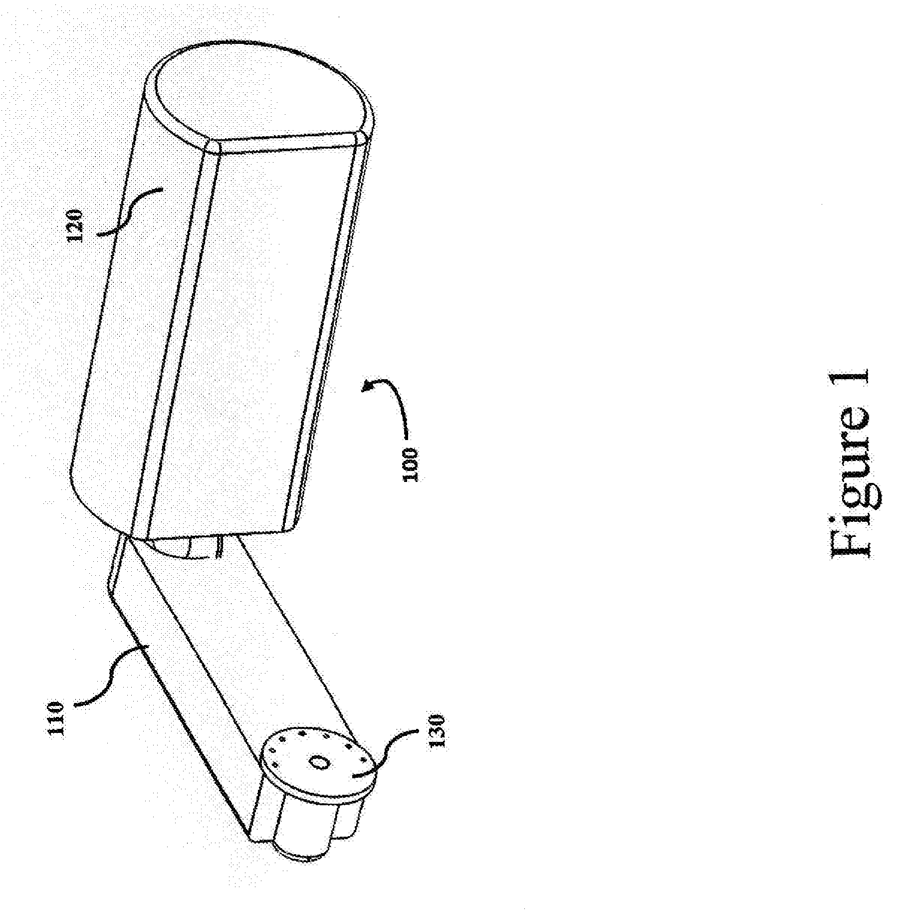
[0010] FIG. 1 is a detail of the apparatus, in accordance with one or more embodiments of the present disclosure.
[0011] FIG. 2 is a detail of the schematic of the socket mechanism, in accordance with one or more embodiments of the present disclosure.
[0012] FIG. 3A is a detail of the schematic of a various configuration of the assembly in this case a substantially 180-degree position, in accordance with one or more embodiments of the present disclosure
[0013] FIG. 3A is a detail of the schematic of a various configuration of the assembly in this case a substantially 90-degree position, in accordance with one or more embodiments of the present disclosure
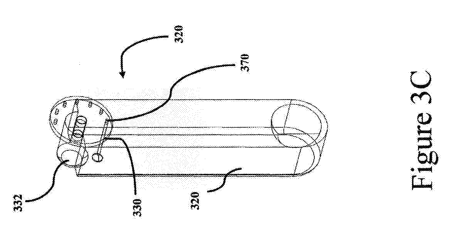
[0014] FIG. 3C is a detail of the schematic of a various configuration of the assembly in this case a substantially 270-degree position, in accordance with one or more embodiments of the present disclosure
[0015] FIG. 4A is a detail of the schematic of a various configuration of the assembly in this case a substantially 45-degree position of its substantially 360-degree capability, in accordance with one or more embodiments of the present disclosure
[0016] FIG. 4B is a detail of the schematic of a various configuration of the assembly in this case a substantially 225-degree position of its substantially 360-degree capability, in accordance with one or more embodiments of the present disclosure
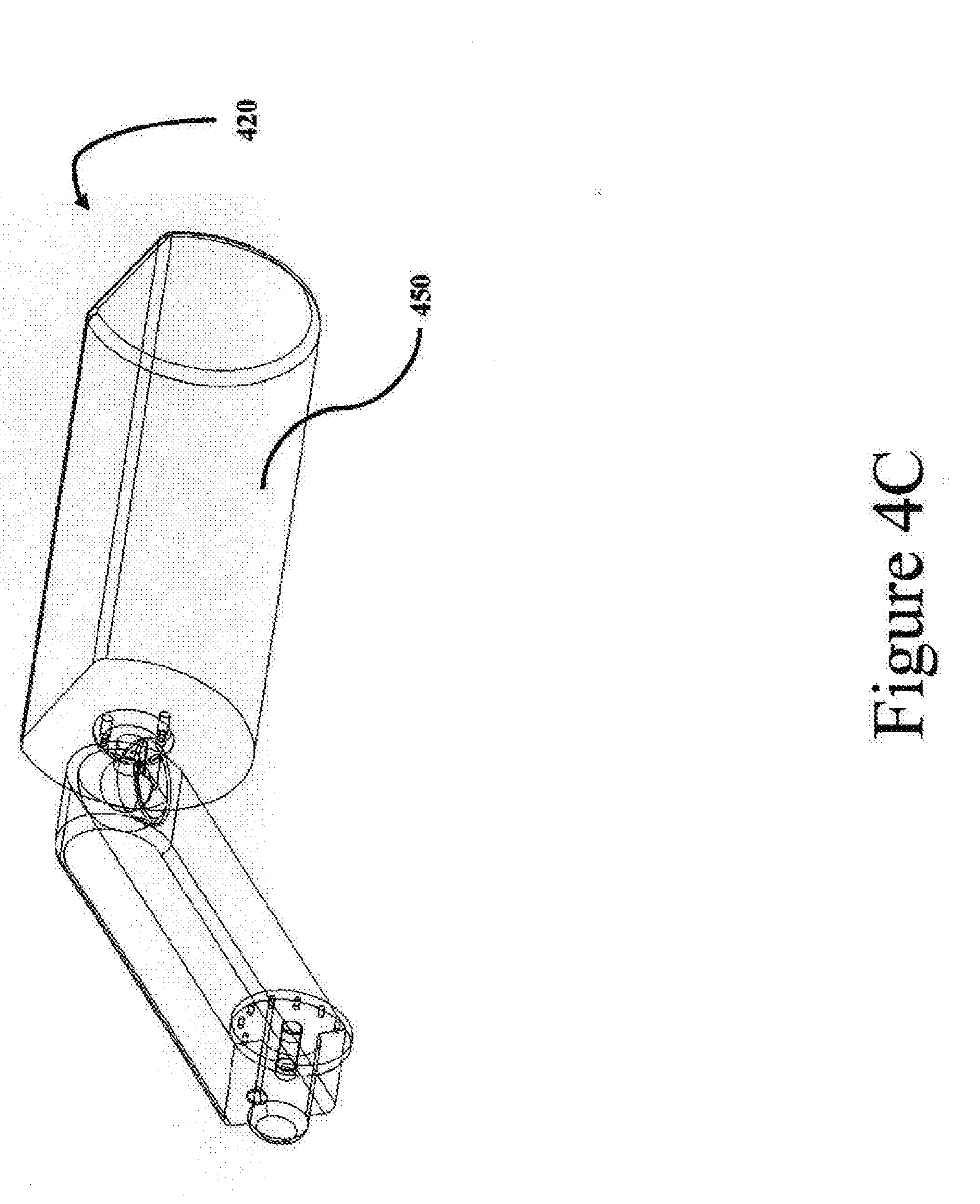
[0017] FIG. 4C is a detail of the schematic of a various configuration of the assembly in this case a substantially 135-degree position of its substantially 360-degree capability, in accordance with one or more embodiments of the present disclosure
[0018] FIG. 5A is a detail of the schematic of a various configuration of the assembly in this case the spring is shown in an uncompressed state in accordance with one or more embodiments of the present disclosure
[0019] FIG. 5B is a detail of the schematic of a various configuration of the assembly in this case the spring is shown in a compressed state due to the coupling of item, in accordance with one or more embodiments of the present disclosure
DETAILED DESCRIPTION
[0020] In the present disclosure the term "about" can allow for a degree of variability in a value or range, for example, within 10%, within 5%, or within 1% of a stated value or of a stated limit of a range.
[0021] In the present disclosure the term "substantially" can allow for a degree of variability in a value or range, for example, within 90%, within 95%, or within 99% of a stated value or of a stated limit of a range.
[0022] For the purposes of promoting an understanding of the principles of the present disclosure, reference will now be made to the embodiments illustrated in the drawings, and specific language will be used to describe the same. It will nevertheless be understood that no limitation of the scope of this disclosure is thereby intended.
[0023] The present disclosure relates to an extendable assembly for a physical fatigue reducing device and more particularly, reconfigurable body load-fatigue reducing devices. In particular, embodiments of the one or more present disclosures relate to portable attachment points on the device allowing a variety of custom configurations and to assist other disabilities to readily handle, the physical stresses of their jobs though out a hour work day.
[0024] Those skilled in the art will recognize that numerous modifications can be made to the specific implementations described above. The implementations should not be limited to the particular limitations described. Other implementations may be possible.
[0025] FIG. 1 is a detail of the apparatus 100 in a compressed locked position, in accordance with one or more embodiments of the present disclosure.
[0026] FIG. 2 is a detail of the schematic of the ball for a socket mechanism 210, in accordance with one or more embodiments of the present disclosure, the adjustable socket mechanism, in one or more embodiments, includes a ball 210, a coupled spring 220, and the socket as shown in FIG. 5A 540.
[0027] FIG. 3A is a detail of the schematic of the swiveling mechanism 332, shown pinned in the substantially 90-degree position 340 in accordance with one or more embodiments of the present disclosure. From FIG. 3A, the adjustable swivel mechanism, in one or more embodiments, includes a male rod portion 432 and recessed female mating portion in 320. In one embodiment, the male rod portion is situated within the recessed female mating portion 320 where it may rotate and be temporarily positioned in one or more locked states. In a further embodiment, a pin 330 is used to configure the position of the armature 320 in various positions in the range between about 0-degrees to 180-degrees by increments of about 7-degrees for each, 340, 345, 350, 355, 360, 365, 370, by inserting the pin 330 into holes in the tertiary support mount 332.
[0028] FIG. 3B is a detail of the schematic of the swiveling mechanism 332, shown pinned in the substantially 180-degree position 355 in accordance with one or more embodiments of the present disclosure. From FIG. 3A, the adjustable swivel mechanism, in one or more embodiments, includes a male rod portion 432 and recessed female mating portion in 320. In one embodiment, the male rod portion is situated within the recessed female mating portion 320 where it may rotate and be temporarily positioned in one or more locked states. In a further embodiment, a pin 330 is used to configure the position of the armature 320 in various positions in the range between about 0-degrees to 180-degrees by increments of about 7-degrees for each, 340, 345, 350, 355, 360, 365, 370, by inserting the pin 330 into holes in the tertiary support mount 332.
[0029] FIG. 3C is a detail of the schematic of the swiveling mechanism 332, shown in the substantially 270-degree position 370 in accordance with one or more embodiments of the present disclosure. From FIG. 3A, the adjustable swivel mechanism, in one or more embodiments, includes a male rod portion 432 and recessed female mating portion in 320. In one embodiment, the male rod portion is situated within the recessed female mating portion 320 where it may rotate and be temporarily positioned in one or more locked states. In a further embodiment, a pin 330 is used to configure the position of the armature 320 in various positions in the range between about 0-degrees to 180-degrees by increments of about 7-degrees for each, (340, 345, 350, 355, 360, 365, 370), by inserting the pin 330 into holes in the tertiary support mount 332.
[0030] FIG. 4A is a detail of the schematic of the socket mechanism 432, in accordance with one or more embodiments of the present disclosure. From FIG. 4A, the adjustable socket mechanism, in one or more embodiments, includes a ball 432 and socket mechanism 434. In one embodiment, the ball 434 is situated within the socket 434 where it may rotate and be temporarily positioned in one or more locked states. In a further embodiment, the ball 432 is configured so the spring 530 from FIG. 5B is coupled with the ball wherein the ball and spring may move in a synchronized manner. In a further embodiment, the socket is configured to be attached or integral with a base 434.
[0031] FIG. 4B is a detail of the apparatus 440 in a further rotated position of substantially 225-degree of the about possible 360-degree range, in accordance with one or more embodiments of the present disclosure. In one embodiment, the base of 440 of the apparatus further comprises a ball joint 432 allowing rotation within the socket joint 434, wherein the distal plate may be locked, fully or temporarily, with the base by twisting the load bearing surface in relation to the armature 436.
[0032] FIG. 4C is a detail of the apparatus 440 in a further rotated position of substantially 135-degree of the possible about 360-degree range, in accordance with one or more embodiments of the present disclosure. In one embodiment, the base of 440 of the apparatus further comprises a ball joint 432 allowing rotation within the socket joint 434, wherein the distal plate may be locked, fully or temporarily, with the base by twisting the load bearing surface in relation to the armature 436.
[0033] FIG. 5A is a detail of the apparatus 530 in a compressed locked position, in accordance with one or more embodiments of the present disclosure. In one embodiment, the base 540 of the apparatus further comprises a ball socket 545 for coupling to the base, wherein the base may be locked, fully or temporarily, with the base by twisting the plate in relation to the base 540.
[0034] FIG. 5B is a detail of the apparatus 530 in a compressed locked position, in accordance with one or more embodiments of the present disclosure. In one embodiment, the base 540 of the apparatus further comprises a ball socket 545 for coupling to the base, wherein the base may be locked, fully or temporarily, with the base by twisting the plate in relation to the base 540.
* * * * *
D00000
D00001
D00002
D00003
D00004
D00005
D00006
D00007
D00008
XML
uspto.report is an independent third-party trademark research tool that is not affiliated, endorsed, or sponsored by the United States Patent and Trademark Office (USPTO) or any other governmental organization. The information provided by uspto.report is based on publicly available data at the time of writing and is intended for informational purposes only.
While we strive to provide accurate and up-to-date information, we do not guarantee the accuracy, completeness, reliability, or suitability of the information displayed on this site. The use of this site is at your own risk. Any reliance you place on such information is therefore strictly at your own risk.
All official trademark data, including owner information, should be verified by visiting the official USPTO website at www.uspto.gov. This site is not intended to replace professional legal advice and should not be used as a substitute for consulting with a legal professional who is knowledgeable about trademark law.