Vent Pipe And Blower Comprising The Same
LIANG; Chenglin ; et al.
U.S. patent application number 16/455804 was filed with the patent office on 2019-10-17 for vent pipe and blower comprising the same. The applicant listed for this patent is Zhongshan Broad-Ocean Motor Co., Ltd.. Invention is credited to Huixiu CHEN, Wei LEI, Chenglin LIANG, Shuangxi SONG, Baixian XIAO, Hongmei ZHAO.
| Application Number | 20190316792 16/455804 |
| Document ID | / |
| Family ID | 59377404 |
| Filed Date | 2019-10-17 |


View All Diagrams
| United States Patent Application | 20190316792 |
| Kind Code | A1 |
| LIANG; Chenglin ; et al. | October 17, 2019 |
VENT PIPE AND BLOWER COMPRISING THE SAME
Abstract
A vent pipe, including: a top plate; two side plates; a base plate; and an air channel formed by the top plate, the two side plates, and the base plate; and an air deflector. The air channel includes a first air inlet and a first air outlet. The air deflector is disposed on the base plate and located on one side of the first air outlet. Also provided is a blower, including a motor; a volute; a blade wheel; and the vent pipe. The volute includes a chamber and the blade wheel is disposed in the chamber. The volute includes a second air inlet and a second air outlet both communicating with the chamber. The motor is disposed on the volute. The vent pipe communicates with the second air outlet.
| Inventors: | LIANG; Chenglin; (Zhongshan, CN) ; ZHAO; Hongmei; (Zhongshan, CN) ; LEI; Wei; (Zhongshan, CN) ; SONG; Shuangxi; (Zhongshan, CN) ; XIAO; Baixian; (Zhongshan, CN) ; CHEN; Huixiu; (Zhongshan, CN) | ||||||||||
| Applicant: |
|
||||||||||
|---|---|---|---|---|---|---|---|---|---|---|---|
| Family ID: | 59377404 | ||||||||||
| Appl. No.: | 16/455804 | ||||||||||
| Filed: | June 28, 2019 |
Related U.S. Patent Documents
| Application Number | Filing Date | Patent Number | ||
|---|---|---|---|---|
| PCT/CN2017/077743 | Mar 22, 2017 | |||
| 16455804 | ||||
| Current U.S. Class: | 1/1 |
| Current CPC Class: | F04D 29/4226 20130101; F04D 29/441 20130101; F24F 13/08 20130101; F04D 17/16 20130101; F24F 7/065 20130101 |
| International Class: | F24F 7/06 20060101 F24F007/06; F24F 13/08 20060101 F24F013/08; F04D 17/16 20060101 F04D017/16 |
Foreign Application Data
| Date | Code | Application Number |
|---|---|---|
| Dec 29, 2016 | CN | 201621462159.6 |
Claims
1. A vent pipe, comprising: 1) a top plate; 2) two side plates; 3) a base plate; 4) an air channel formed by the top plate, the two side plates, and the base plate, and the air channel comprising a first air inlet and a first air outlet; and 5) an air deflector disposed on the base plate and located on one side of the first air outlet.
2. The vent pipe of claim 1, wherein the air deflector is perpendicular to the base plate.
3. The vent pipe of claim 2, wherein one end of the base plate extends out of the air channel to form an extension plate, and the air deflector is disposed on the extension plate.
4. The vent pipe of claim 2, wherein the air deflector is disposed in the air channel.
5. The vent pipe of claim 1, wherein the two side plates are integrated with the top plate.
6. The vent pipe of claim 2, wherein the two side plates are integrated with the top plate.
7. The vent pipe of claim 3, wherein the two side plates are integrated with the top plate.
8. The vent pipe of claim 4, wherein the two side plates are integrated with the top plate.
9. The vent pipe of claim 5, wherein lower ends of the two side plates bend away from the air channel to form convex flanges; two sides of the base plate extend to form clamping units; and the convex flanges are clamped by the clamping units.
10. The vent pipe of claim 6, wherein lower ends of the two side plates bend away from the air channel to form convex flanges; two sides of the base plate extend to form clamping units; and the convex flanges are clamped by the clamping units.
11. The vent pipe of claim 7, wherein lower ends of the two side plates bend away from the air channel to form convex flanges; two sides of the base plate extend to form clamping units; and the convex flanges are clamped by the clamping units.
12. The vent pipe of claim 8, wherein lower ends of the two side plates bend away from the air channel to form convex flanges; two sides of the base plate extend to form clamping units; and the convex flanges are clamped by the clamping units.
13. The vent pipe of claim 9, wherein the air channel is rectangular in shape.
14. The vent pipe of claim 10, wherein the air channel is rectangular in shape.
15. The vent pipe of claim 11, wherein the air channel is rectangular in shape.
16. The vent pipe of claim 12, wherein the air channel is rectangular in shape.
17. A blower, comprising: a motor; a volute; a blade wheel; and a vent pipe of claim 1; wherein: the volute comprises a chamber and the blade wheel is disposed in the chamber; the volute comprises a second air inlet and a second air outlet both communicating with the chamber; the motor is disposed on the volute; and the vent pipe communicates with the second air outlet.
18. The blower of claim 17, wherein: the volute comprises a top surface provided with a plurality of mounting holes; a mounting plate is fixed on the top surface via the plurality of mounting holes and comprises a through hole; the motor is disposed on the mounting plate and comprises a revolving shaft; a front end of the revolving shaft of the motor passes through the through hole of the mounting plate to connect to the blade wheel in the chamber.
Description
CROSS-REFERENCE TO RELAYED APPLICATIONS
[0001] This application is a continuation-in-part of International Patent Application No. PCT/CN2017/077743 with an international filing date of Mar. 22, 2017, designating the United States, now pending, and further claims foreign priority benefits to Chinese Patent Application No. 201621462159.6 filed Dec. 29, 2016. The contents of all of the aforementioned applications, including any intervening amendments thereto, are incorporated herein by reference. Inquiries from the public to applicants or assignees concerning this document or the related applications should be directed to: Matthias Scholl PC., Attn.: Dr. Matthias Scholl Esq., 245 First Street, 18th Floor, Cambridge, Mass. 02142.
BACKGROUND
[0002] This disclosure relates to a vent pipe and a blower comprising the same.
[0003] Typically, a blower includes a motor, a volute including an air inlet and an air outlet, a blade wheel, and a vent pipe communicating with the air outlet. The vent pipe is composed of four flat plates, and the air volume and static pressure of the vent pipe cannot be adjustable.
SUMMARY
[0004] Disclosed is a vent pipe and a blower comprising the same. An air deflector is disposed in the vent pipe to adjust the air volume and static pressure in the vent pipe.
[0005] The disclosure provides a vent pipe, comprising: a top plate; two side plates; a base plate; an air channel formed by the top plate, the two side plates, and the base plate, and the air channel comprising a first air inlet and a first air outlet; and an air deflector disposed on the base plate and located on one side of the first air outlet.
[0006] The air deflector can be perpendicular to the base plate.
[0007] One end of the base plate can extend out of the air channel to form an extension plate, and the air deflector can be disposed on the extension plate.
[0008] The air deflector can be disposed in the air channel.
[0009] The two side plates can be integrated with the top plate.
[0010] The lower ends of the two side plates can bend away from the air channel to form convex flanges; two sides of the base plate can extend to form clamping units; and the convex flanges can be clamped by the clamping units.
[0011] The air channel can be rectangular in shape.
[0012] Also provided is a blower, comprising a motor; a volute; a blade wheel; and the aforesaid vent pipe. The volute comprises a chamber and the blade wheel is disposed in the chamber; the volute comprises a second air inlet and a second air outlet both communicating with the chamber; the motor is disposed on the volute; and the vent pipe communicates with the second air outlet.
[0013] The volute can comprise a top surface provided with a plurality of mounting holes; a mounting plate can be fixed on the top surface via the plurality of mounting holes and can comprise a through hole; the motor can be disposed on the mounting plate and can comprise a revolving shaft; the front end of the revolving shaft of the motor can pass through the through hole of the mounting plate to connect to the blade wheel in the chamber.
[0014] Advantages of the vent pipe and a blower comprising the same as described in the disclosure are summarized as follows.
[0015] 1. The base plate of the vent pipe is provided with an air deflector, so that the air volume and static pressure in the vent pipe are adjustable.
[0016] 2. The air deflector is perpendicular to the base plate. The design is cost-effective.
[0017] 3. The air deflector is disposed in the air channel or on an extension plate of the base plate. The arrangement is flexible.
[0018] 4. The lower ends of the two side plates are bent away from the air channel to form convex flanges; two sides of the base plate extend to form clamping units; and the convex flanges are clamped by the clamping units. The connection of the base plate and the two side plates is firm and reliable.
BRIEF DESCRIPTION OF THE DRAWINGS
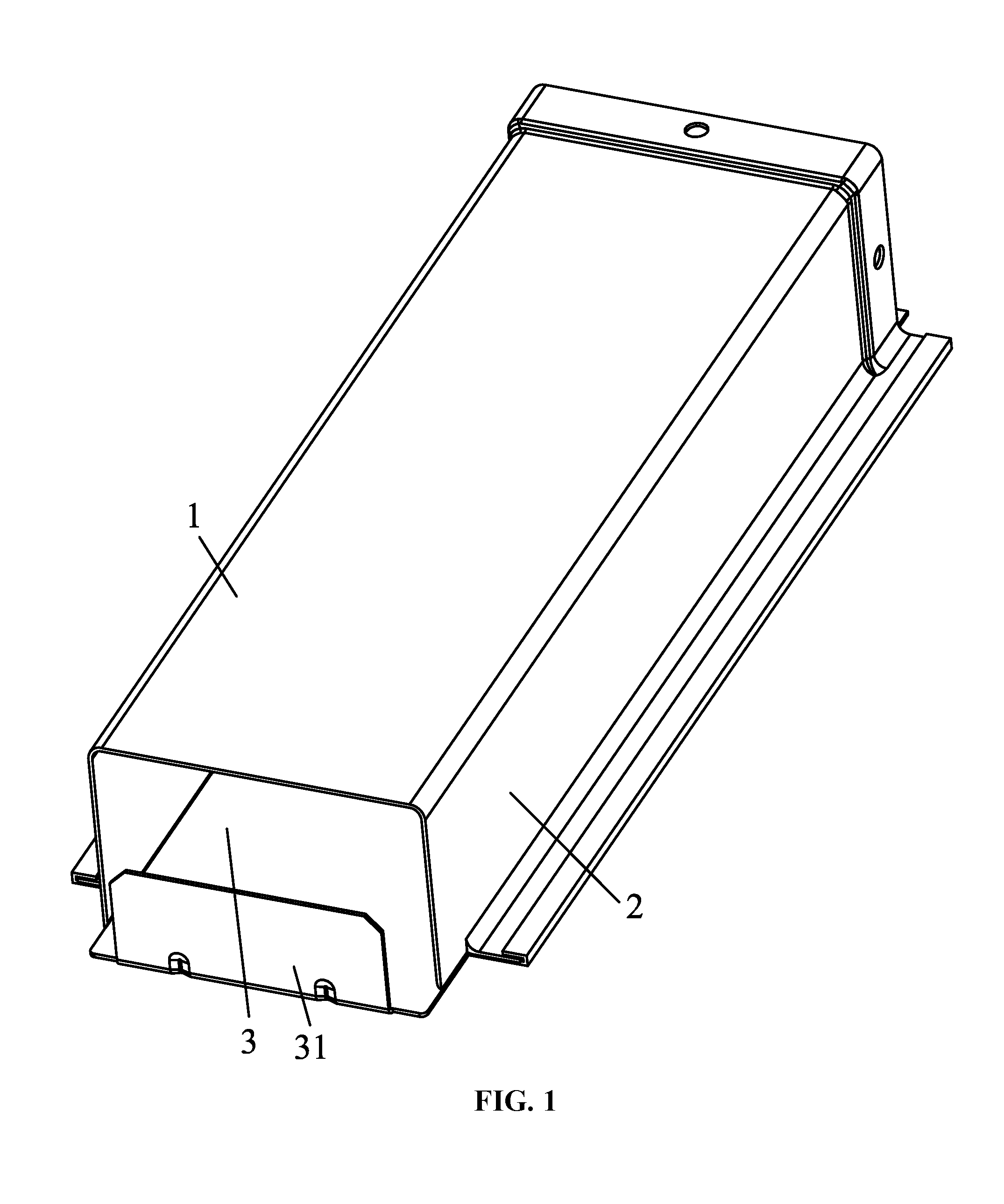
[0019] FIG. 1 is a schematic diagram of a vent pipe in Example 1;
[0020] FIG. 2 is an exploded view of a vent pipe in Example 1;
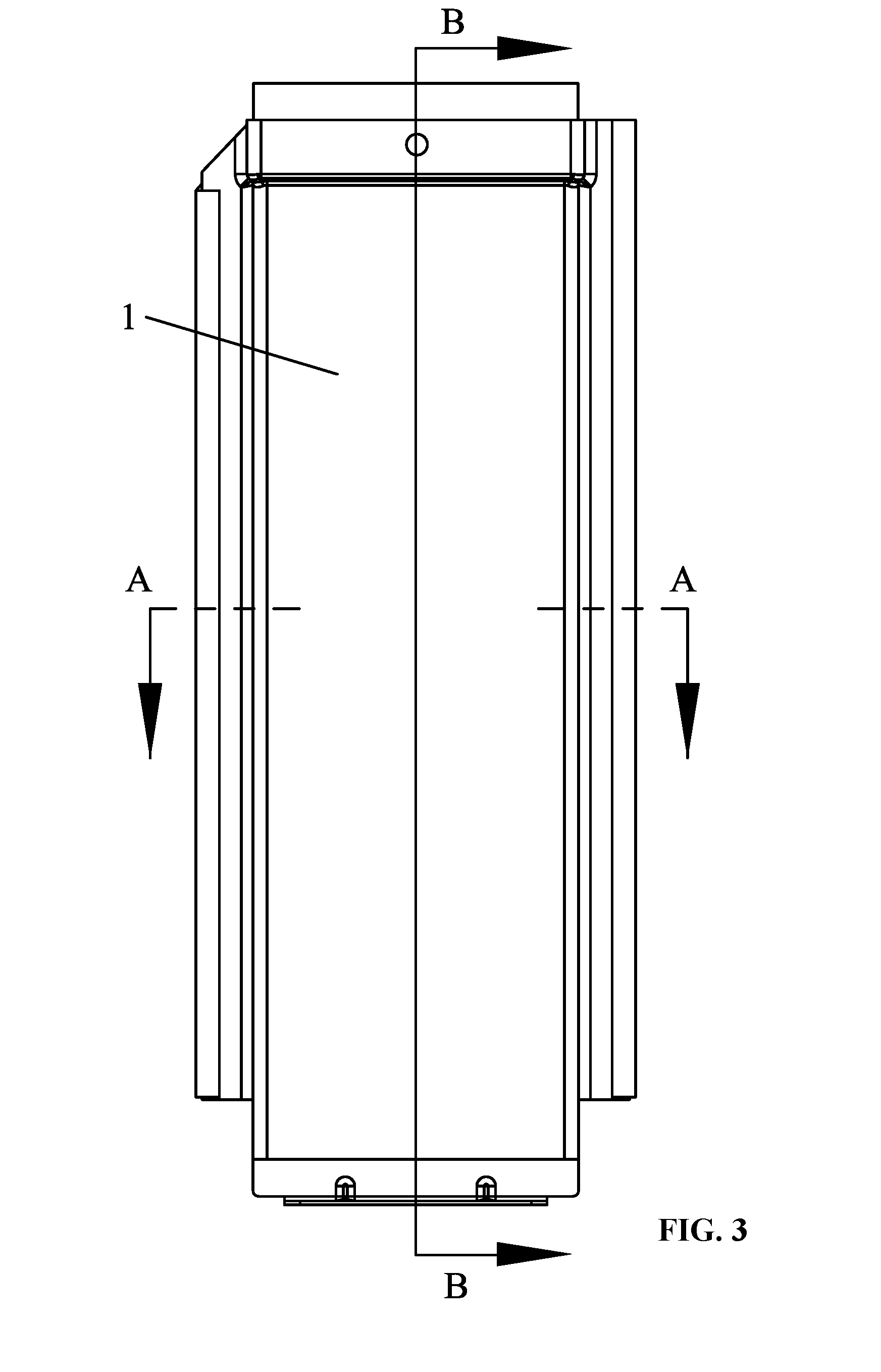
[0021] FIG. 3 is a front view of a vent pipe in Example 1;
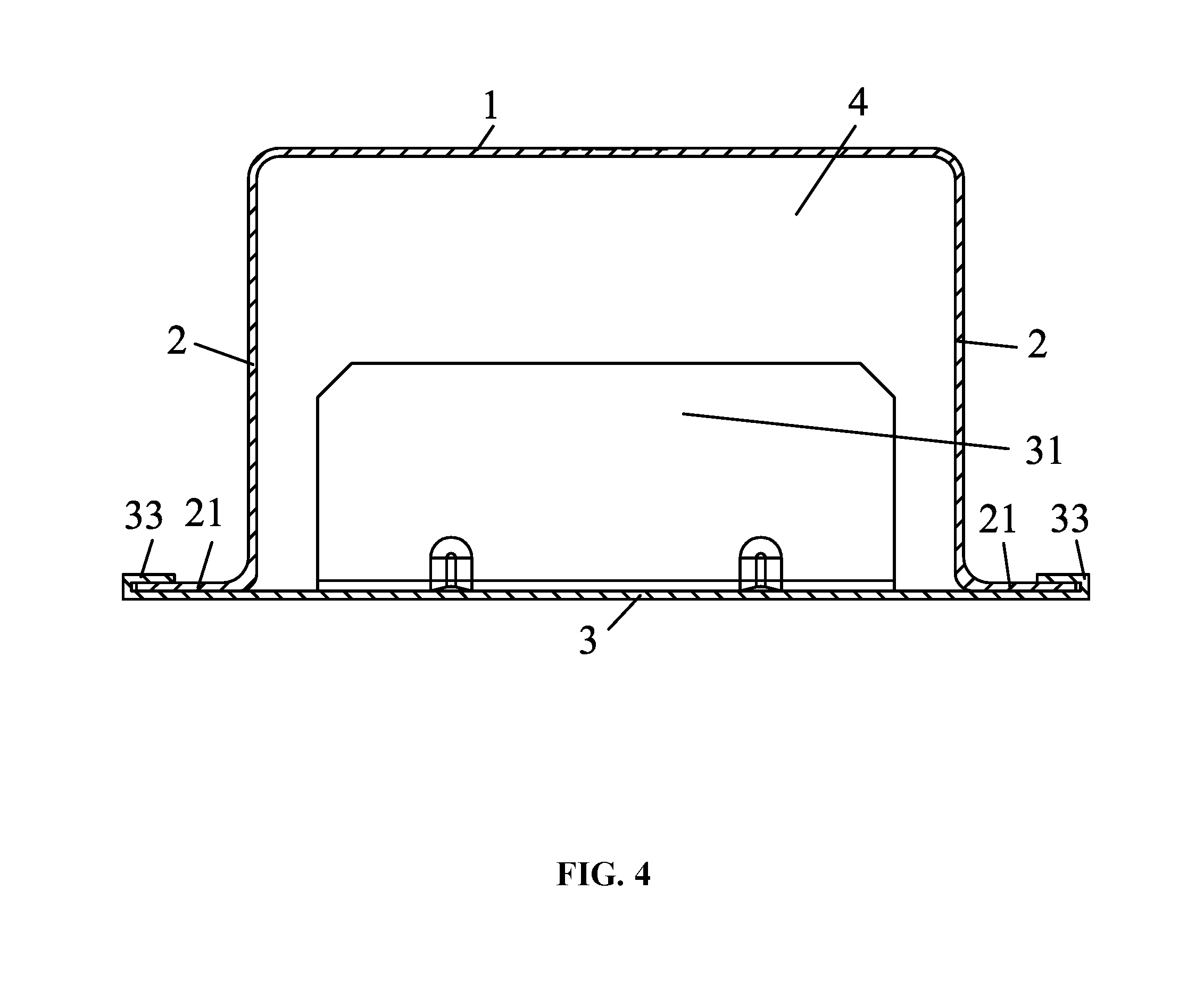
[0022] FIG. 4 is a sectional view taken from line A-A in FIG. 3;
[0023] FIG. 5 is a sectional view taken from line B-B in FIG. 3;
[0024] FIG. 6 is a schematic diagram of a vent pipe in Example 2;
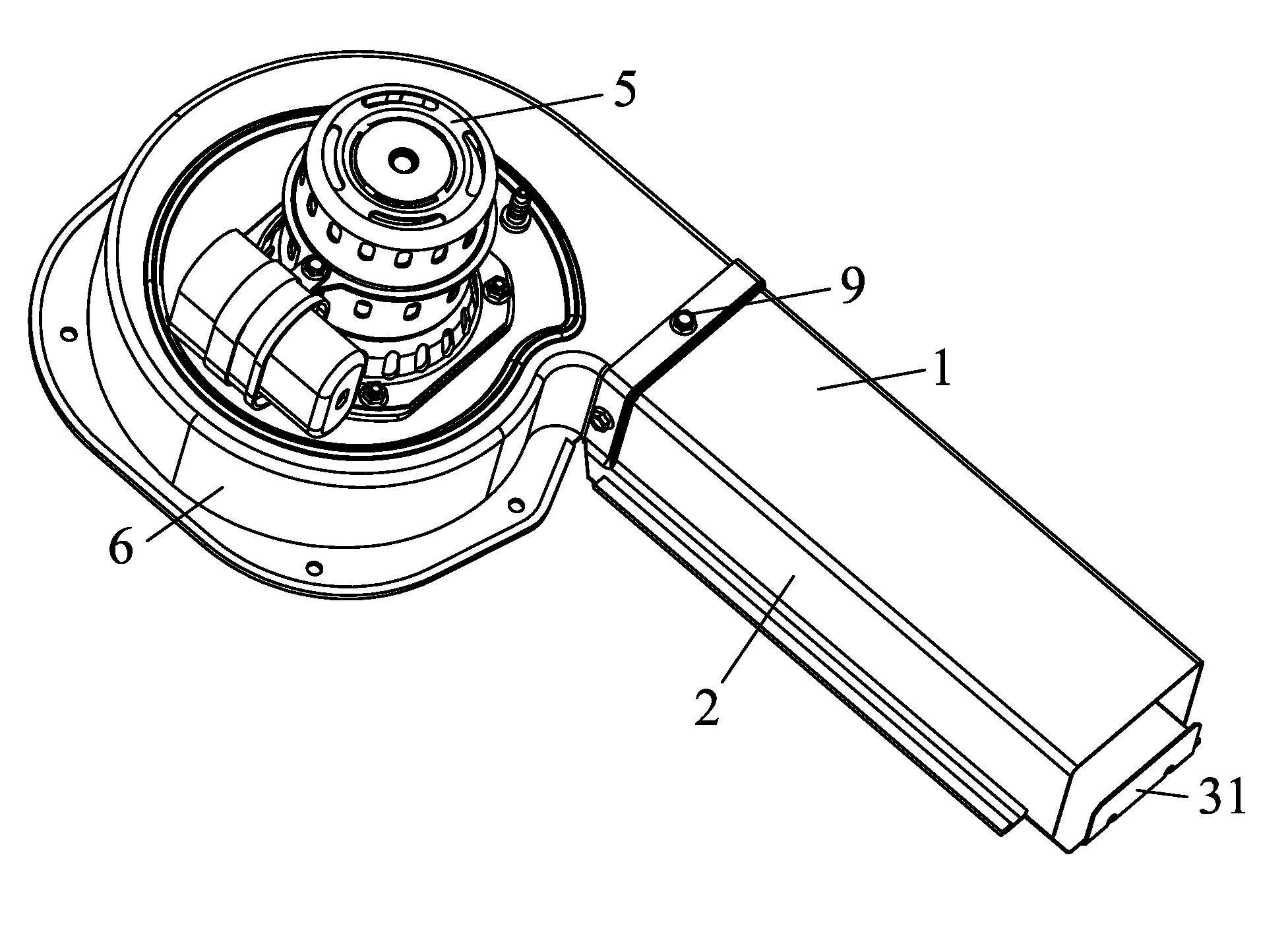
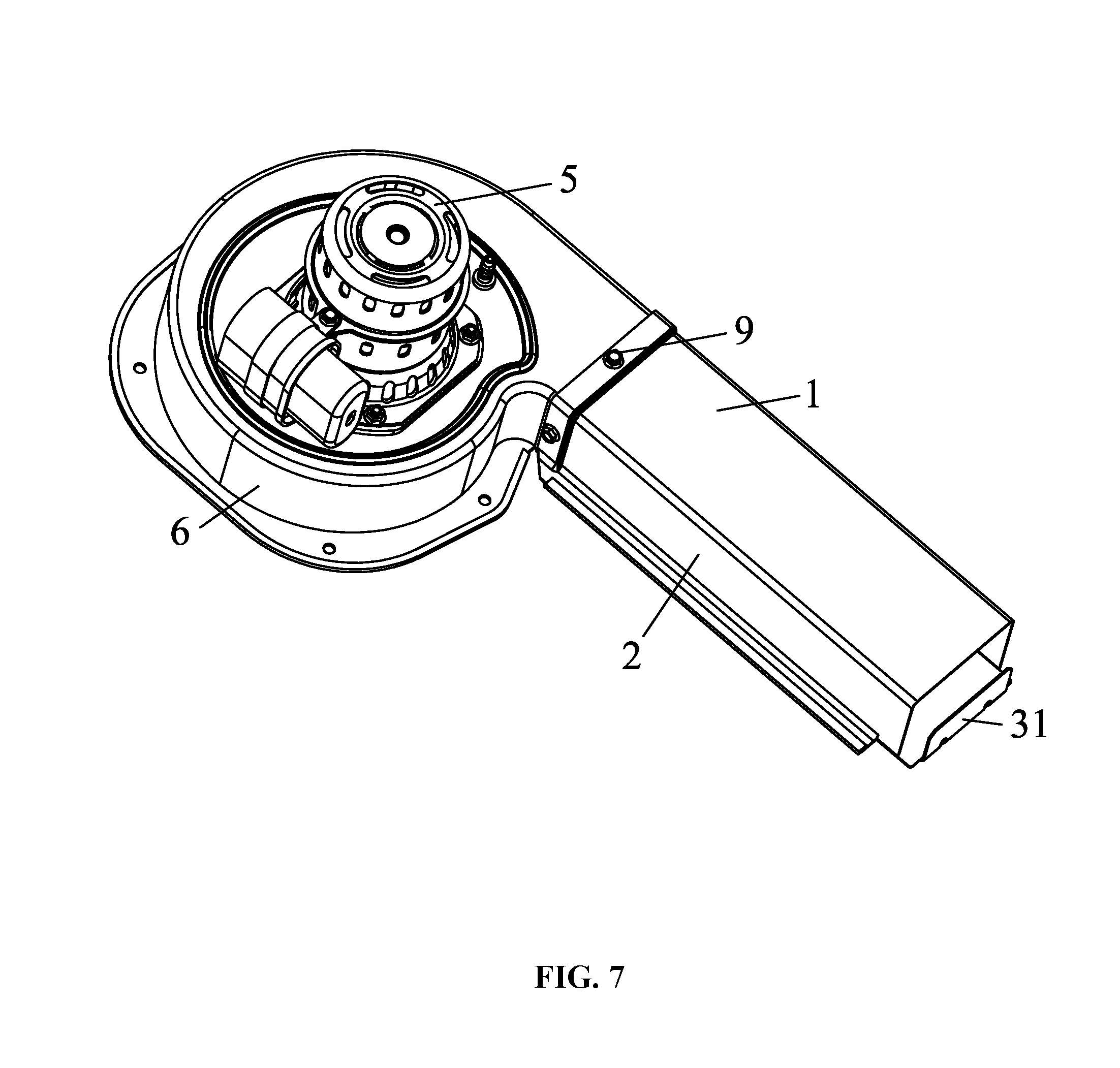
[0025] FIG. 7 is a schematic diagram of a blower in Example 3;
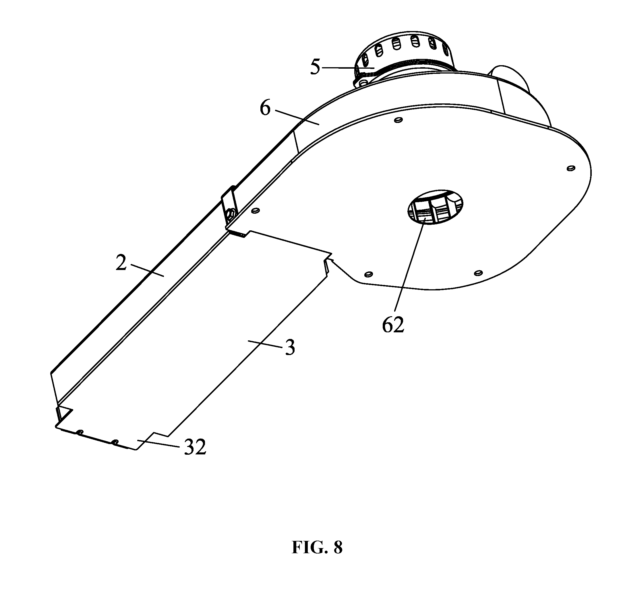
[0026] FIG. 8 is a schematic diagram of a blower in Example 3 in another angle of view;
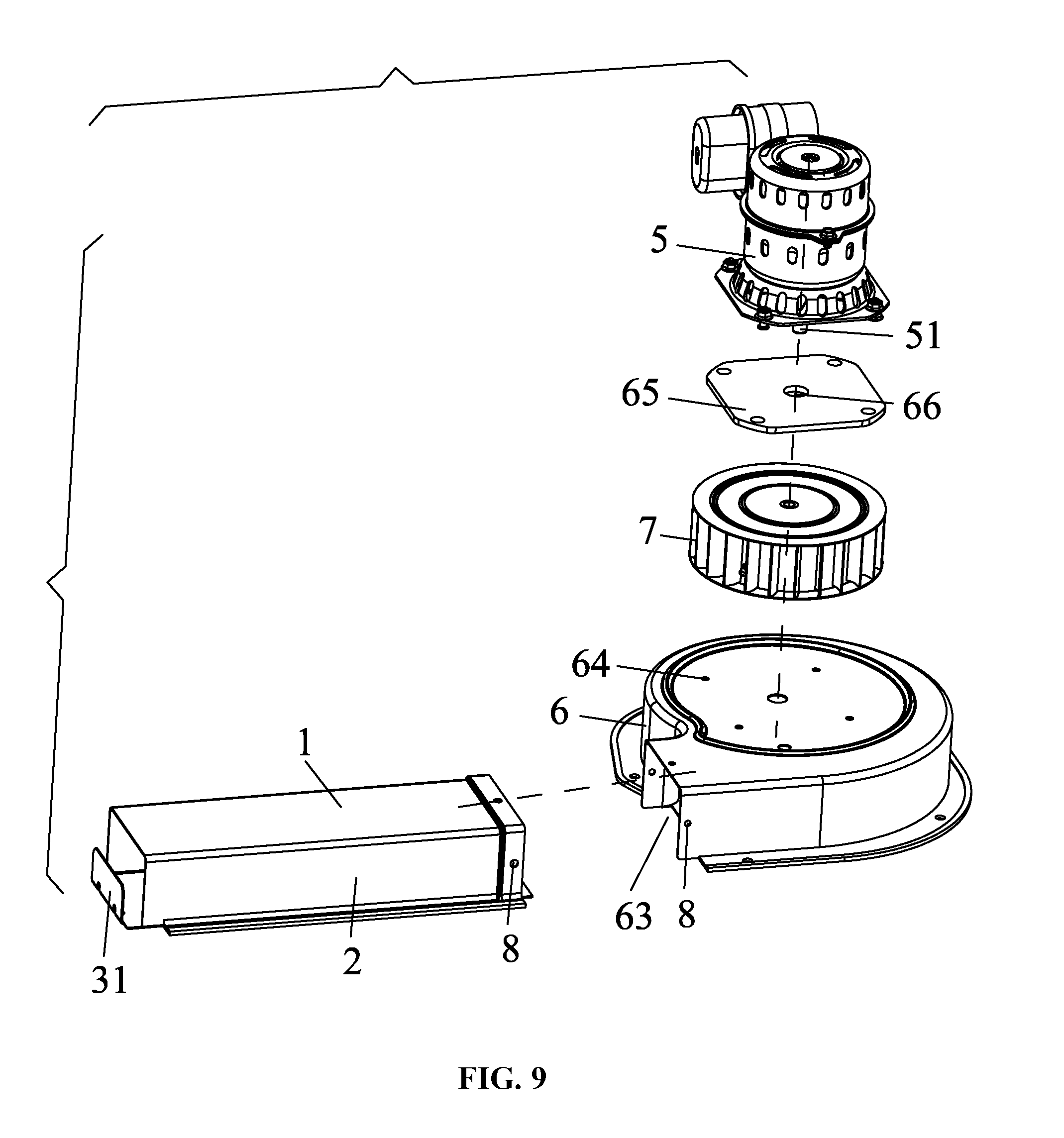
[0027] FIG. 9 is an exploded view of a blower in Example 3;
[0028] FIG. 10 is a front view of a blower in Example 3; and
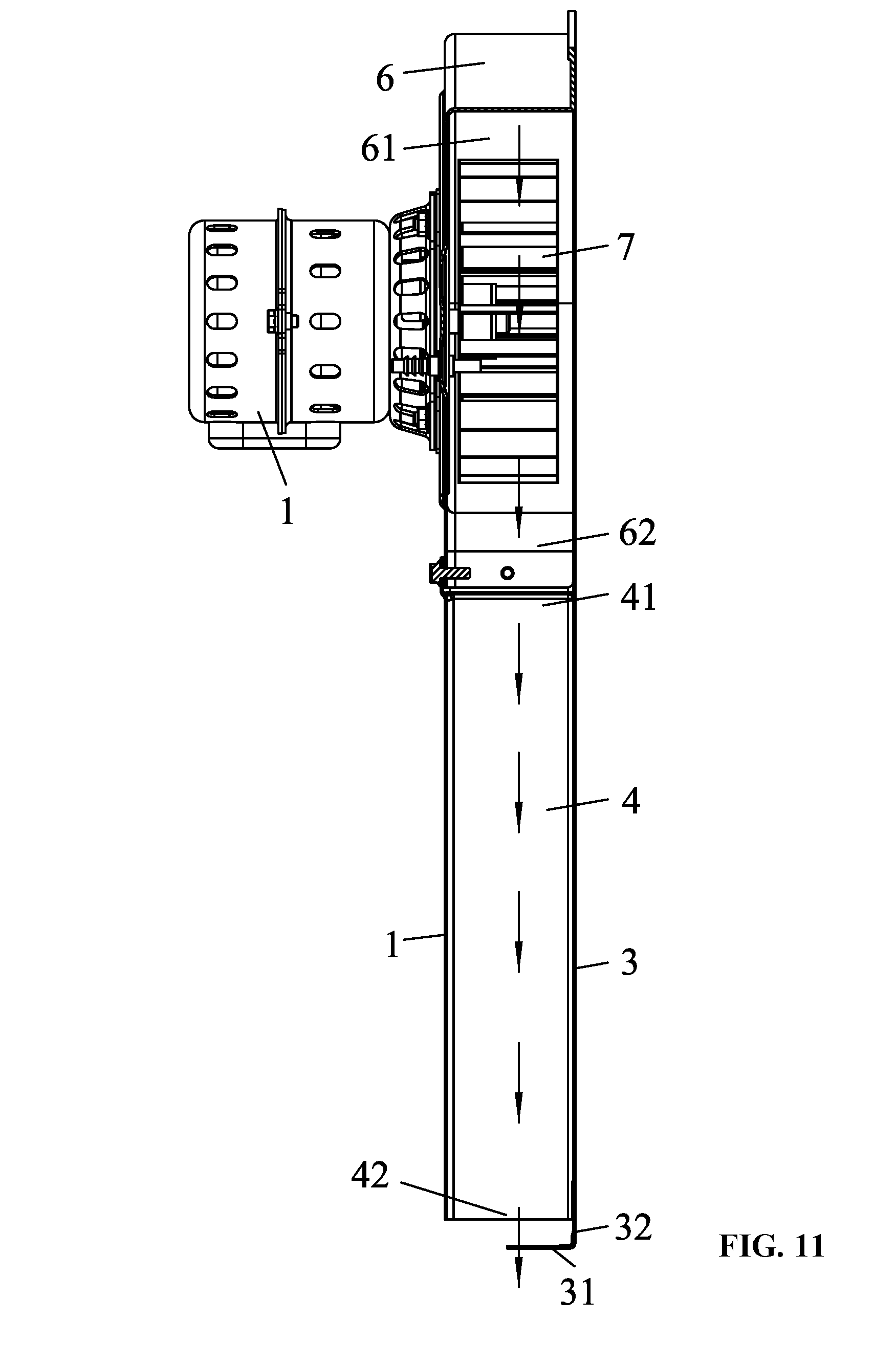
[0029] FIG. 11 is a sectional view taken from line C-C in FIG. 10.
DETAILED DESCRIPTION
[0030] To further illustrate, embodiments detailing a vent pipe and a blower comprising the same are described below. It should be noted that the following embodiments are intended to describe and not to limit the disclosure.
[0031] As shown in FIGS. 1-5, provided is a vent pipe comprising a top plate 1; two side plates 2; and a base plate 3; and an air channel 4 formed by the top plate 1, the two side plates 2, and the base plate 3. The air channel 4 comprises a first air inlet 41 and a first air outlet 42. The base plate 3 comprises an air deflector 31 disposed at the first air outlet 42.
[0032] The air deflector 31 is perpendicular to the base plate 3.
[0033] One end of the base plate 3 extends out of the air channel 4 to form an extension plate 32, and the air deflector 31 is disposed on the extension plate 32.
[0034] The two side plates 2 are integrated with the top plate 1.
[0035] The lower ends of the two side plates 2 bend away from the air channel to form convex flanges 21; two sides of the base plate 3 extend to form clamping units 33; and the convex flanges 21 are clamped by the clamping units 33.
[0036] The air channel 4 is rectangular in shape.
[0037] Optionally, the air deflector 31 is disposed in the air channel 4, as shown in FIG. 6.
[0038] As shown in FIGS. 7-11, a blower comprises a motor 5, a volute 6, a blade wheel 7, and the aforesaid vent pipe. The volute 6 comprises a chamber 61 and the blade wheel 7 is disposed in the chamber 61; the volute 6 comprises a second air inlet 62 and a second air outlet 63 both communicating with the chamber 61; the motor is disposed on the volute 6; and the vent pipe communicates with the second air outlet 63. The vent pipe is integrated with the volute or fixed on the volute via bolts. For example, the first air inlet 41 of the vent pipe is provided with a first screw hole 8, the second air outlet 63 of the volute 6 is provided with a second screw hole 8, and the first air inlet 41 of the exhaust extension pipe and the second air outlet 63 of the volute are tightly connected by the bolts 9.
[0039] The volute 6 comprises a top surface provided with a plurality of mounting holes 64; a mounting plate 65 is fixed on the top surface via the plurality of mounting holes 64 and comprises a through hole 66; the motor 5 is disposed on the mounting plate 65 and comprises a revolving shaft 51; the front end of the revolving shaft 51 of the motor 5 passes through the through hole 66 of the mounting plate 65 to connect to the blade wheel 7 in the chamber 61.
[0040] Working principle: the air channel 4 formed by the top plate 1, the two side plates 2, and the base plate 3 comprises the first air inlet 41 and the first air outlet 42; the base plate 3 comprises the air deflector 31 disposed at the first air outlet 42; the volute 6 comprises a second air inlet 62 and a second air outlet 63, and the vent pipe communicates with the second air outlet 63, so that the air volume and static pressure in the vent pipe are adjustable. The air deflector 31 is perpendicular to the base plate 3. The design is cost-effective. The air deflector 31 is disposed in the air channel 4 or on an extension plate 32 of the base plate 3, so it is flexible in arrangement. The lower ends of the two side plates 2 bend away from the air channel to form convex flanges 21; two sides of the base plate 3 extend to form clamping units 33; and the convex flanges 21 are clamped by the clamping units 33. The connection of the base plate 3 and the two side plates 2 is reliable.
[0041] It will be obvious to those skilled in the art that changes and modifications may be made, and therefore, the aim in the appended claims is to cover all such changes and modifications.
* * * * *
D00000
D00001
D00002
D00003
D00004
D00005
D00006
D00007
D00008
D00009
D00010
D00011
XML
uspto.report is an independent third-party trademark research tool that is not affiliated, endorsed, or sponsored by the United States Patent and Trademark Office (USPTO) or any other governmental organization. The information provided by uspto.report is based on publicly available data at the time of writing and is intended for informational purposes only.
While we strive to provide accurate and up-to-date information, we do not guarantee the accuracy, completeness, reliability, or suitability of the information displayed on this site. The use of this site is at your own risk. Any reliance you place on such information is therefore strictly at your own risk.
All official trademark data, including owner information, should be verified by visiting the official USPTO website at www.uspto.gov. This site is not intended to replace professional legal advice and should not be used as a substitute for consulting with a legal professional who is knowledgeable about trademark law.