Constant Efficiency Controller
Schlachter; John James ; et al.
U.S. patent application number 16/456947 was filed with the patent office on 2019-10-17 for constant efficiency controller. This patent application is currently assigned to Maxitrol Company. The applicant listed for this patent is Maxitrol Company. Invention is credited to Lynn E. Cooper, Nicholas Roth Hanawalt, Mark Geoffrey Masen, Frank P. Mimick, John James Schlachter.
| Application Number | 20190316775 16/456947 |
| Document ID | / |
| Family ID | 57015790 |
| Filed Date | 2019-10-17 |


| United States Patent Application | 20190316775 |
| Kind Code | A1 |
| Schlachter; John James ; et al. | October 17, 2019 |
CONSTANT EFFICIENCY CONTROLLER
Abstract
A system and controller where the pressure of the air is continuously monitored or read at a designated exhaust point and adjustments made to the flow of the air and gas to keep the efficiency of the appliance at a maximum to control the appliance (or the burner for an appliance) within specifications as dictated by the customer or consumer rather than training the user.
| Inventors: | Schlachter; John James; (Leonard, MI) ; Masen; Mark Geoffrey; (Leonard, MI) ; Mimick; Frank P.; (Watauga, TX) ; Hanawalt; Nicholas Roth; (Detroit, MI) ; Cooper; Lynn E.; (North Richland Hills, TX) | ||||||||||
| Applicant: |
|
||||||||||
|---|---|---|---|---|---|---|---|---|---|---|---|
| Assignee: | Maxitrol Company Southfield MI |
||||||||||
| Family ID: | 57015790 | ||||||||||
| Appl. No.: | 16/456947 | ||||||||||
| Filed: | June 28, 2019 |
Related U.S. Patent Documents
| Application Number | Filing Date | Patent Number | ||
|---|---|---|---|---|
| 15085536 | Mar 30, 2016 | |||
| 16456947 | ||||
| 62140153 | Mar 30, 2015 | |||
| Current U.S. Class: | 1/1 |
| Current CPC Class: | F23N 1/022 20130101; F23N 5/184 20130101; F04D 27/004 20130101; F04D 25/08 20130101 |
| International Class: | F23N 5/18 20060101 F23N005/18; F04D 25/08 20060101 F04D025/08; F23N 1/02 20060101 F23N001/02; F04D 27/00 20060101 F04D027/00 |
Claims
1. A circuit for a heating appliance connected to a fuel source, said circuit comprising: at least one fuel passageway coupled to the fuel source; a valve in communication with the at least one fuel passageway and configured to modulate the pressure of the fuel in said at least one fuel passageway; at least one air passageway; a fan in communication with the at least one air passageway, said fan including a variable speed motor configured to manipulate the fan to regulate the vacuum air pressure within the at least one air passageway; a fuel pressure sensor configured to measure a fuel pressure within the at least one fuel passageway; an air pressure sensor configured to measure a vacuum air pressure within the at least one air passageway; a controller in communication with said variable speed motor of the fan and said valve, said controller configured to adjust the speed of said variable speed motor and to adjust the position of said valve; a testing device configured to determine a target fuel pressure and a target air pressure to achieve a desired air to fuel ratio as defined in an optimum performance specification provided by the manufacturer of the heating appliance; a comparator configured to compare the fuel pressure measured by the fuel pressure sensor to the target fuel pressure and to compare the vacuum air pressure measured by the air pressure sensor to the target air pressure during operation of the heating appliance and determine any variance between the target fuel pressure or target air pressure as determined by the testing device; a signal generator in communication with said comparator and said controller, said signal generator configured to indicate a signal to the controller if the comparator determines there is any variance with the target fuel pressure and the fuel pressure and/or target air pressure and the vacuum air pressure as defined in the optimum performance specification; and wherein the controller is configured to adjust the fan speed and/or the valve in response to any variance of the target fuel pressure and target air pressure to the fuel pressure and vacuum air pressure to achieve the desired air to gas ratio as defined in the optimum performance specification.
2. A method of operating a burner, the burner having a controller in communication with variable speed motor coupled to a fan and a modulating valve, said method comprising the steps of: obtaining an optimum performance specification for the burner that defines an optimum operating efficiency for the burner, the optimum performance specification stored on the controller; deriving an internal vacuum air pressure target from the optimum performance specification; sensing a combustion vacuum air pressure using a first sensor; comparing the combustion vacuum air pressure to the derived internal vacuum air pressure target; manipulating the variable speed motor of the fan until the sensed combustion vacuum air pressure is within an acceptable deviation of the derived internal vacuum air pressure target; deriving a gas pressure target from the optimum performance specification; sensing a burner gas pressure using a second sensor; comparing the burner gas pressure to the derived gas pressure target; and manipulating the modulating valve until the sensed burner gas pressure is within an acceptable deviation of the derived gas pressure target.
3. A method of operating a burner used in a heating appliance having a controller, passageways for combustion air and burner gas, at least one fan having a motor to control the speed of the fan by the controller, and an air pressure sensors for measuring combustion air pressure and a fuel pressure sensor for measuring burner gas pressure, said method comprising the steps of: obtaining an optimum performance specification of the heating appliance that defines an optimum operating efficiency for the heating appliance; testing the heating appliance using a testing device to determine the combustion air pressure and burner gas pressure at an optimum operating efficiency as defined by the optimum performance specification of the heating appliance to determine a target control parameter; inputting the target control parameter into the controller; comparing the air vacuum pressure from the sensors to the target control parameter; sending a signal to the controller to generate a digital instruction to the controller to control the gas valve; sensing burner gas pressure; changing the speed of the fan motor if the signal indicates a variance from optimum operating efficiency to return to target control parameter relating to the fan motor speed; changing the position of the gas valve if the signal indicates a variance from optimum operating efficiency to return to target control parameter relating to the burner gas pressure; and further monitoring and changing as needed for further optimum operating efficiency of the heating appliance.
4. The circuit for a heating appliance of claim 1, wherein the testing device is an orifice.
Description
RELATED APPLICATIONS
[0001] This application is a continuation of U.S. patent application Ser. No. 15/085,536, filed on Mar. 30, 2016, which claims priority to and the benefit of U.S. Provisional Patent Application No. 62/140,153, filed on Mar. 30, 2015, the entire contents of which are hereby incorporated by reference.
TECHNICAL FIELD
[0002] The subject matter relates to a controller for heating operations.
BACKGROUND
[0003] In the present invention pressure of the manifold gas pressure and the vacuum air pressure are continuously monitored or read at a designated exhaust point and makes adjustments to the flow of the air and gas to keep the efficiency of the appliance at a maximum to control the appliance (or the burner for an appliance) rather than training the user.
[0004] The subject invention also provides a method that helps eliminate repetitive, unnecessary, and sometimes harmful switching of the speed of the fan. As the switching of the motor speed may cause damage to various electrical components, such as relays and transistors, the method serves to prevent optimum switching of the fan to run at an optimum speed. The method also promotes proper operation of burner at its optimum state.
BRIEF DESCRIPTION OF THE DRAWINGS
[0005] Other advantages of the present invention will be readily appreciated, as the same becomes better understood by reference to the following detailed description when considered in connection with the accompanying drawings wherein:
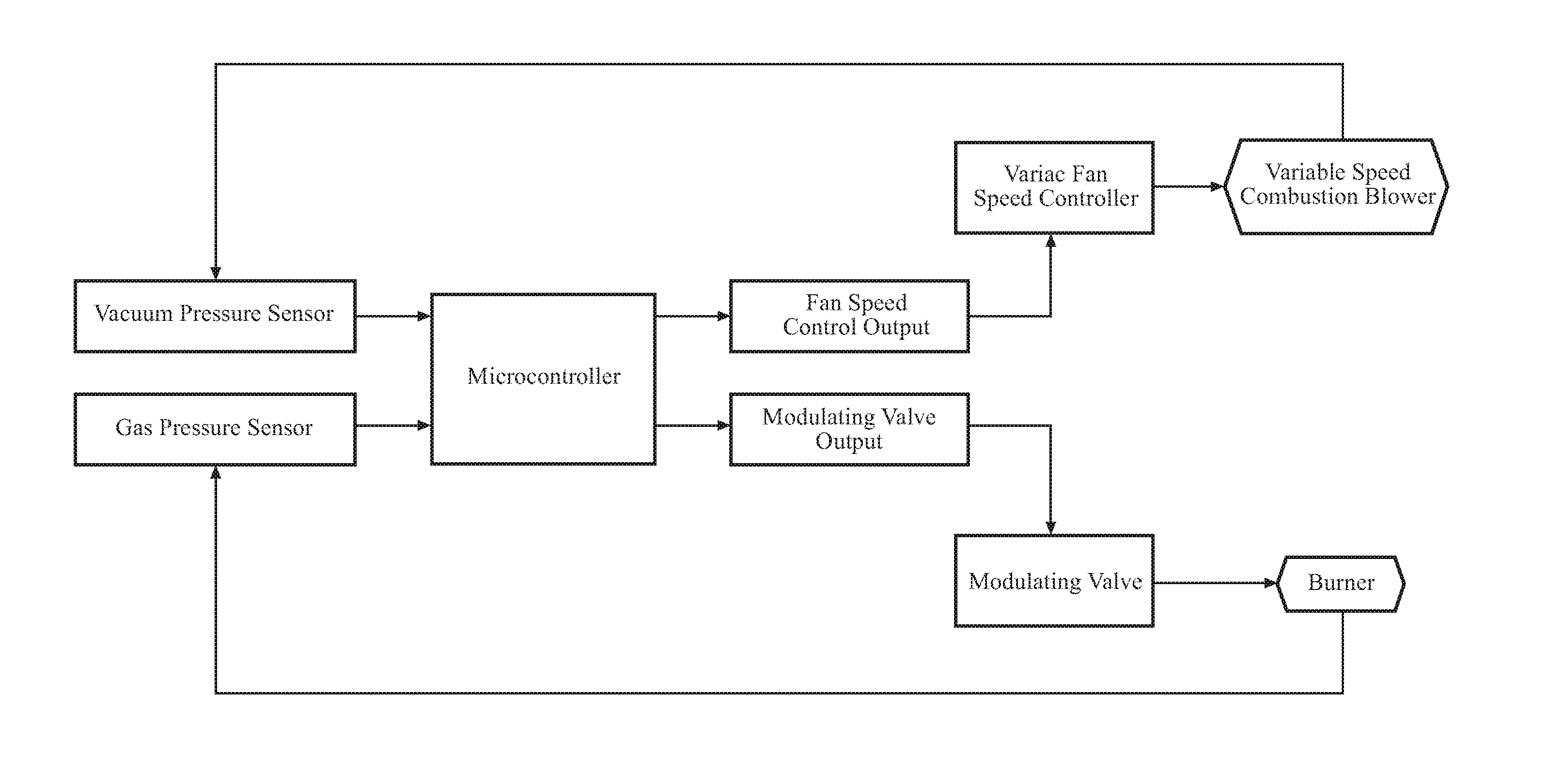
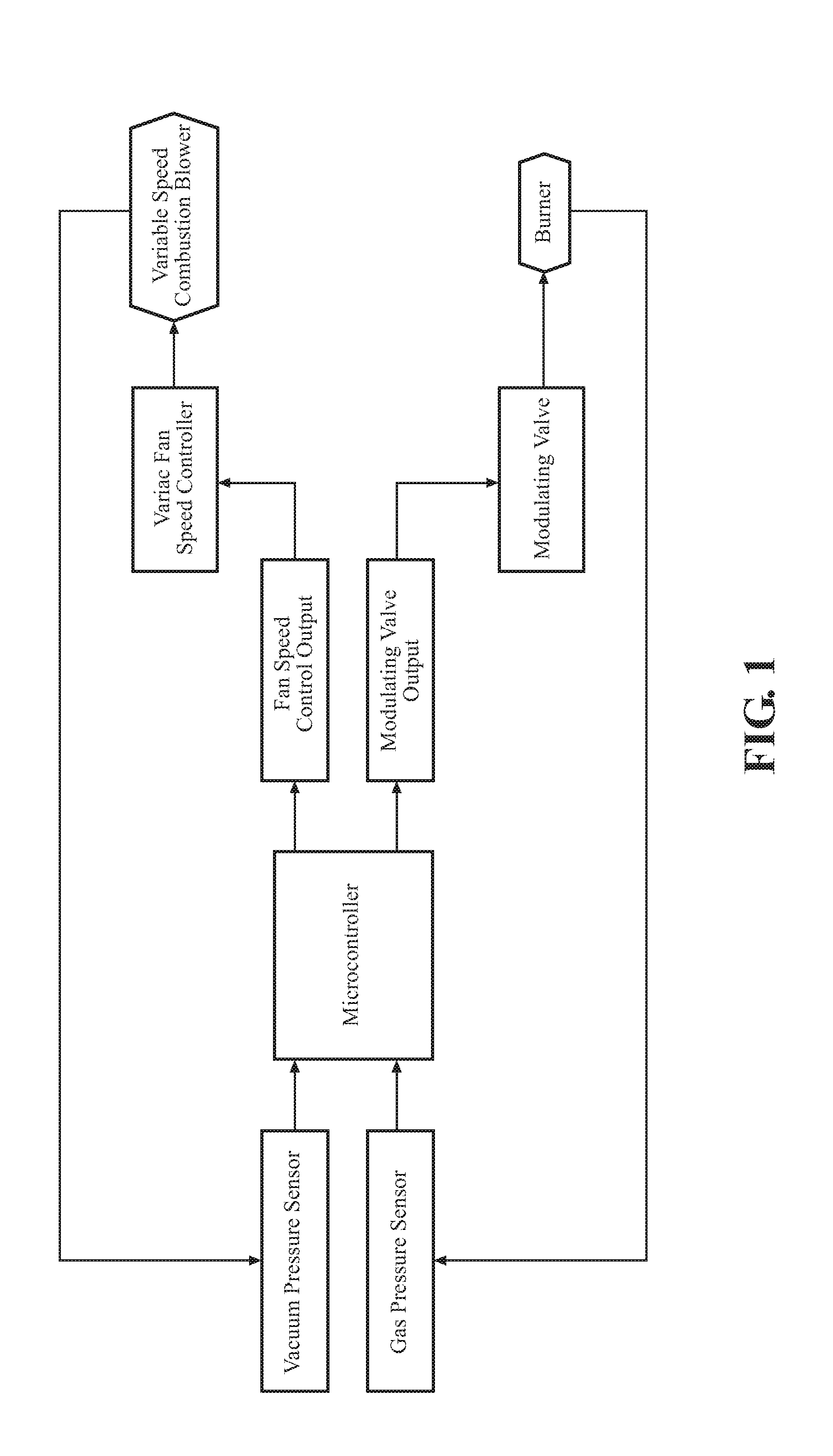
[0006] FIG. 1 is a schematic diagram showing a general representation of the system setup;
[0007] FIG. 2 is a more detailed schematic diagram of the controller in the system;
[0008] FIG. 3 is an elevated perspective view of the gas modulating valve for burner gas pressure in the system;
[0009] FIG. 4 is an elevated perspective view of a testing orifice for the system to set the flow rate equal for the customer's system specifications;
[0010] FIG. 5 is an elevated perspective view of a controller connected to all relevant input and output signals;
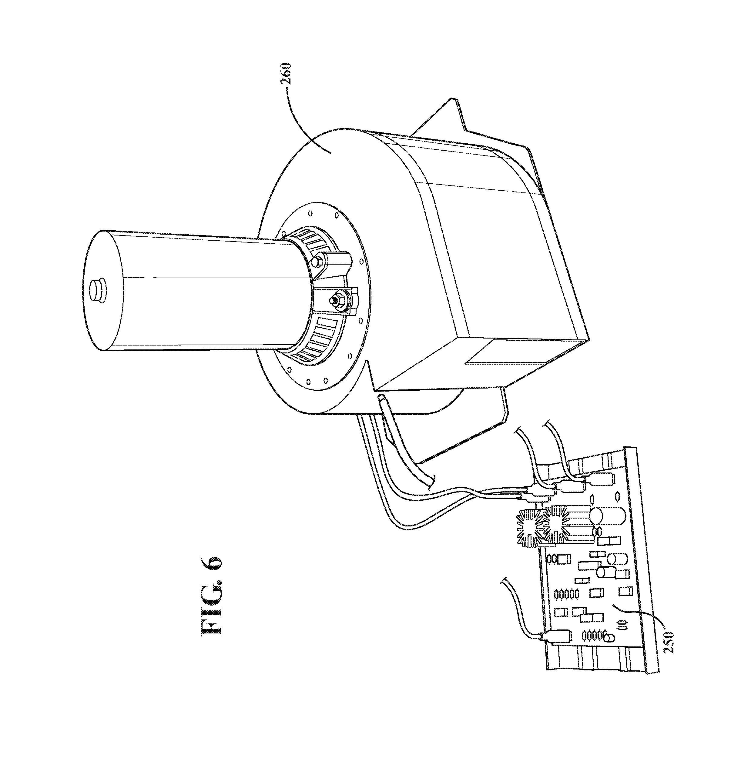
[0011] FIG. 6 is an elevated perspective view of a variac variable speed fan control board and variable speed combustion fan;
[0012] FIG. 7 is an elevated perspective view of a 0'' to 4'' w. c. gas pressure sensor in the system as described; and
[0013] FIG. 8 is an elevated perspective view of a 0''-2'' w. c. vacuum air pressure sensor in the system as described.
DETAILED DESCRIPTION OF THE INVENTION
[0014] Referring to the Figures, a controller 10 in a system 20 is shown herein. This controller 10 is designed to provide a uniform output heat pattern as called for in a specific environment to have a constant efficiency of a burner (ideal for an operating point). The efficiency of the burner is determined by customer or consumer specifications and is tested, as shown in FIG. 4, so that it feeds back to those specifications.
[0015] The controller 10 is designed, as shown in FIG. 1, to bring in two pressures (combustion air pressure and burner gas pressure) and control the fan speed to match an internal table of air pressures. The modulating valve adjusts the burner gas pressure to match the desired air/gas ratio that is programmed into the controller via a microprocessor, microcontroller or equivalent device. FIG. 1 is a general representation of the system setup.
[0016] FIG. 2 provides more detail in the various steps. After testing, an analog control parameter 100 is fed into an A/D input 102 to provide a derived internal air pressure target 104 relating to speed 103 of the fan motor. A PID controller 106 compares the current air vacuum pressure with the derived internal target and sends a control voltage to the motor speed control board 108, thus changing the speed of the fan motor and the vacuum air pressure if not at the speed or pressure needed for optimum performance. A sensor 110 monitors vacuum air pressure (controlled by the motor speed) and transmits via another A/D input 112 to an internal air pressure device for a pressure value 114 which communicates with both the PID controller 106 (to determine if it is within specifications) and also a different portion of the microcontroller to derive the gas pressure target at 116.
[0017] Once this stage is reached, the derived gas pressure target is fed into the gas pressure specification 118 to generate a digital instruction in the PID controller 119 to control the valve 120. A sensor 122 is used at the output of the valve 120 to feed information back to the A/D input 124 into a gas pressure monitor 126 for the valve, where the monitor 126 feeds back into the PID controller 119.
[0018] In operation, the system and controller controls a gas modulating valve 200 (FIG. 3), a control board 250 and variable speed combustion fan 260 (FIG. 6) as monitored by a water column gas pressure sensor 270 (FIG. 7) and a water column vacuum air pressure sensor 280 (FIG. 8). As shown in FIG. 3, a gas modulating valve 200, such as that supplied by Maxitrol under the model number EXA40 PV-7 or similar devices, modulates the burner gas pressure. An example of a 0-4'' water column gas pressure gauge is shown in FIG. 7, and was purchased as a ProSense gauge identified as P356-5026, C24. The water column vacuum air pressure sensor 280 of FIG. 8 was purchased as a ProSense product DPTA-20.
[0019] FIG. 4 illustrates an orifice 210 used in testing to set the flow rate equal to the customer's system specifications. Each customer sets their own optimum performance specifications. The invention herein takes that information and produces the derived gas pressure target, fan motor speed (or air pressure target), and any other information generated as described above.
[0020] The circuit 10 shown can provide a number of advantages. The components of the circuit 10 are preferably supported by one or more printed circuit boards. The printed circuit board 215 (FIG. 5) provides electrical connections between the components and includes the microcontroller. FIG. 5 illustrate a controller connection to all relevant input and output signals. The circuit is suited for providing voltage control signals to the other printed circuit boards for the gas modulating valve (FIG. 3) and the variac and the variable speed fan controller (FIG. 6) to control the variable speed combustion fan 260, as well as reading the sensors 270 and 280. However, those skilled in the art will appreciate other uses for the circuit 10 described herein.
[0021] The present invention has been described herein in an illustrative manner, and it is to be understood that the terminology which has been used is intended to be in the nature of words of description rather than of limitation. Many modifications and variations of the invention are possible in light of the above teachings.
* * * * *
D00000
D00001
D00002
D00003
D00004
D00005
D00006
XML
uspto.report is an independent third-party trademark research tool that is not affiliated, endorsed, or sponsored by the United States Patent and Trademark Office (USPTO) or any other governmental organization. The information provided by uspto.report is based on publicly available data at the time of writing and is intended for informational purposes only.
While we strive to provide accurate and up-to-date information, we do not guarantee the accuracy, completeness, reliability, or suitability of the information displayed on this site. The use of this site is at your own risk. Any reliance you place on such information is therefore strictly at your own risk.
All official trademark data, including owner information, should be verified by visiting the official USPTO website at www.uspto.gov. This site is not intended to replace professional legal advice and should not be used as a substitute for consulting with a legal professional who is knowledgeable about trademark law.