Rotary Cylinder Piston Compressor Pump And Compressor With Rotary Cylinder Piston Compressor Pump
Huang; Hui ; et al.
U.S. patent application number 16/314584 was filed with the patent office on 2019-10-17 for rotary cylinder piston compressor pump and compressor with rotary cylinder piston compressor pump. The applicant listed for this patent is GREE GREEN REFRIGERATION TECHNOLOGY CENTER CO., LTD. OF ZHUHAI. Invention is credited to Liying Deng, Zhongcheng Du, Yusheng Hu, Hui Huang, Jia Xu.
| Application Number | 20190316586 16/314584 |
| Document ID | / |
| Family ID | 57114560 |
| Filed Date | 2019-10-17 |

| United States Patent Application | 20190316586 |
| Kind Code | A1 |
| Huang; Hui ; et al. | October 17, 2019 |
ROTARY CYLINDER PISTON COMPRESSOR PUMP AND COMPRESSOR WITH ROTARY CYLINDER PISTON COMPRESSOR PUMP
Abstract
A rotary cylinder piston compressor pump is provided, including a rotating shaft (2), a piston (3) and a cylinder (4). A rotating shaft hole (21) is provided in the rotating shaft (2). An oil guiding channel communicated with the rotating shaft hole (21) is provided in the cylinder (4). A recess (45) is formed in the inner end face of the cylinder (4). An oil path sealed relative to a compression cavity of the cylinder (4) is formed between the recess (45) and the piston (3). The oil path is communicated with an oil path between the piston (3) and the rotating shaft (2) and is communicated with the oil guiding channel by means of an oil returning channel. Also provided is a compressor including the compressor pump.
| Inventors: | Huang; Hui; (Guangdong, CN) ; Hu; Yusheng; (Guangdong, CN) ; Deng; Liying; (Guangdong, CN) ; Du; Zhongcheng; (Guangdong, CN) ; Xu; Jia; (Guangdong, CN) | ||||||||||
| Applicant: |
|
||||||||||
|---|---|---|---|---|---|---|---|---|---|---|---|
| Family ID: | 57114560 | ||||||||||
| Appl. No.: | 16/314584 | ||||||||||
| Filed: | February 17, 2017 | ||||||||||
| PCT Filed: | February 17, 2017 | ||||||||||
| PCT NO: | PCT/CN2017/073923 | ||||||||||
| 371 Date: | December 31, 2018 |
| Current U.S. Class: | 1/1 |
| Current CPC Class: | F04C 2240/60 20130101; F04C 2210/22 20130101; F04C 18/00 20130101; F04C 15/0088 20130101; F04C 2240/603 20130101; F04C 29/023 20130101; F04C 2/344 20130101; F04C 15/06 20130101; F04C 15/0057 20130101 |
| International Class: | F04C 29/02 20060101 F04C029/02; F04C 18/00 20060101 F04C018/00 |
Foreign Application Data
| Date | Code | Application Number |
|---|---|---|
| Jul 29, 2016 | CN | 201610614674.X |
Claims
1. A rotary cylinder piston compressor pump, comprising a rotating shaft (2), a piston (3) and a cylinder (4), a rotating shaft hole (21) being provided in the rotating shaft (2), and an oil guiding channel communicated with the rotating shaft hole (21) being provided in the cylinder (4), wherein a recess (45) is formed in an inner end face of the cylinder (4), an oil path sealed relative to a compression cavity of the cylinder (4) is formed between the recess (45) and the piston (3), and the oil path is communicated with an oil path between the piston (3) and the rotating shaft (2) and is communicated with the oil guiding channel by means of an oil returning channel.
2. The rotary cylinder piston compressor pump as claimed in claim 1, wherein the oil returning channel comprises a cylinder oil hole (46) provided on the cylinder (4), and the cylinder oil hole (46) penetrates through a bottom of the recess (45) and an outer surface of the cylinder (4).
3. The rotary cylinder piston compressor pump as claimed in claim 2, wherein the cylinder (4) comprises a cylinder short shaft (42), the oil returning channel further comprises a cylinder short shaft hole (47) provided on the cylinder short shaft (42), the cylinder short shaft hole (47) is communicated with the cylinder oil hole (46), and the cylinder short shaft hole (47) penetrates through an inner surface and an outer surface of the cylinder short shaft (42).
4. The rotary cylinder piston compressor pump as claimed in claim 1, wherein an intersection area of the rotating shaft hole (21) and the oil guiding channel is not less than 20% of a cross-sectional area of the rotating shaft hole (21).
5. The rotary cylinder piston compressor pump as claimed in claim 1, wherein the cylinder (4) comprises a cylinder short shaft (42), and the oil guiding channel is a cylinder hole (43) provided in the cylinder short shaft (42).
6. The rotary cylinder piston compressor pump as claimed in claim 1, wherein the oil guiding channel is an oil guiding pipe (7); the cylinder (4) comprises a cylinder short shaft (42), the cylinder short shaft (42) is provided with a through hole structure (48) for providing a moving space for movement of the oil guiding pipe (7), and the oil guiding pipe (7) is disposed in the through hole structure (48); and one end of the oil guiding pipe (7) is mounted on the rotating shaft (2), an outlet end of the oil guiding pipe (7) is butted with the rotating shaft hole (21), and an oil guiding sheet (8) is disposed in the oil guiding pipe (7).
7. The rotary cylinder piston compressor pump as claimed in claim 1, wherein a rotating shaft hole oil guiding sheet (22) is disposed in the rotating shaft hole (21).
8. The rotary cylinder piston compressor pump as claimed in claim 1, wherein a piston oil hole (31) penetrating through an inner surface and an outer surface of the piston (3) is provided on a side wall of the piston (3).
9. The rotary cylinder piston compressor pump as claimed in claim 1, wherein an inlet end of the rotating shaft hole (21) is a tapered structure flared outward.
10. The rotary cylinder piston compressor pump as claimed in claim 4, wherein the cylinder (4) comprises a cylinder short shaft (42), and the oil guiding channel is a cylinder hole (43) provided in the cylinder short shaft (42).
11. The rotary cylinder piston compressor pump as claimed in claim 4, wherein the oil guiding channel is an oil guiding pipe (7); the cylinder (4) comprises a cylinder short shaft (42), the cylinder short shaft (42) is provided with a through hole structure (48) for providing a moving space for movement of the oil guiding pipe (7), and the oil guiding pipe (7) is disposed in the through hole structure (48); and one end of the oil guiding pipe (7) is mounted on the rotating shaft (2), an outlet end of the oil guiding pipe (7) is butted with the rotating shaft hole (21), and an oil guiding sheet (8) is disposed in the oil guiding pipe (7).
12. A compressor, comprising a rotary cylinder piston compressor pump, the rotary cylinder piston compressor pump comprising a rotating shaft (2), a piston (3) and a cylinder (4), a rotating shaft hole (21) being provided in the rotating shaft (2), and an oil guiding channel communicated with the rotating shaft hole (21) being provided in the cylinder (4), wherein a recess (45) is formed in an inner end face of the cylinder (4), an oil path sealed relative to a compression cavity of the cylinder (4) is formed between the recess (45) and the piston (3), and the oil path is communicated with an oil path between the piston (3) and the rotating shaft (2) and is communicated with the oil guiding channel by means of an oil returning channel.
Description
[0001] The present application claims benefit of Chinese Patent Application No. 201610614674.X, filed to the China Patent Office on Jul. 29, 2016, entitled "Rotary Cylinder Piston Compressor Pump and Compressor with the Rotary Cylinder Piston Compressor Pump", the contents of which are hereby incorporated in its entirety by this reference.
TECHNICAL FIELD
[0002] The present disclosure relates to a technical field of compressors, and more particularly to a rotary cylinder piston compressor pump and a compressor with the rotary cylinder piston compressor pump.
BACKGROUND
[0003] A rotary cylinder piston compressor belongs to a refrigeration piston compressor of a brand new structure, which essentially adopts a cross slider structure principle. Referring to FIG. 10, O1 is the center of a rotating shaft, O2 is the center of a cylinder, e is a center-to-center distance (i.e., eccentric amount of the compressor), and a square is the center of mass of a piston. When the rotating shaft rotates, the piston is driven to move in a circular motion, and the distance between the piston and the center of the cylinder is in the range of 0 to e. The rotating shaft is eccentrically assembled with the cylinder, and the rotating shaft drives the cylinder to rotate through the piston. Due to the eccentric relationship between the rotating shaft and the cylinder, the rotating shaft and the cylinder rotate around the respective axes during operation, and the piston reciprocates relative to the cylinder to achieve gas compression.
[0004] Specifically, the rotating shaft of the rotary cylinder piston compressor is eccentrically assembled with the cylinder, the rotating shaft drives the cylinder to rotate through the piston, and oil is pumped through a short shaft hole in a cylinder short shaft to a rotating shaft hole in the rotating shaft of the cylinder. Due to the eccentric relationship between the rotating shaft and the cylinder, the rotating shaft and the cylinder rotate around the respective axes during operation. On the one hand, the contact between the lower end surface of the rotating shaft and the end surface of the cylinder ensures the oil supply of the rotating shaft, but brings adverse influence on the circulation of an oil groove oil channel on the side surface of the rotating shaft, which is not conducive to the lubrication the kinematic pair of the rotating shaft and the piston under heavy working conditions. On the other hand, an intersection area of the inner hole of the rotating shaft and the inner hole of the cylinder rotating shaft has a great influence on the oil supply of the rotating shaft.
[0005] In view of the above problems, there is a need for a rotary cylinder piston compressor pump and a compressor with the rotary cylinder piston compressor pump, which can solve the problem in the conventional art of large circulation resistance of an oil groove oil channel on the side surface of a rotating shaft.
SUMMARY
[0006] An objective of the present disclosure is to provide a rotary cylinder piston compressor pump, which can solve the problem in the conventional art of large circulation resistance of an oil groove oil channel on the side surface of a rotating shaft.
[0007] Another objective of the present disclosure is to provide a compressor adopting the rotary cylinder piston compressor pump as described above.
[0008] In order to achieve the objectives, the present disclosure adopts the following technical solutions.
[0009] A rotary cylinder piston compressor pump includes a rotating shaft, a piston and a cylinder, wherein a rotating shaft hole is provided in the rotating shaft, an oil guiding channel communicated with the rotating shaft hole is provided in the cylinder, a recess is formed in the inner end face of the cylinder, an oil path sealed relative to a compression cavity of the cylinder is formed between the recess and the piston, and the oil path is communicated with an oil path between the piston and the rotating shaft and is communicated with the oil guiding channel by means of an oil returning channel.
[0010] As a preferred solution of the above rotary cylinder piston compressor pump, the oil returning channel includes a cylinder oil hole provided on the cylinder, and the cylinder oil hole penetrates through the bottom of the recess and the outer surface of the cylinder.
[0011] As a preferred solution of the above rotary cylinder piston compressor pump, the oil returning channel further includes a cylinder short shaft hole provided on a cylinder short shaft, the cylinder short shaft hole is communicated with the cylinder oil hole, and the cylinder short shaft hole penetrates through the inner surface and the outer surface of the cylinder short shaft.
[0012] As a preferred solution of the above rotary cylinder piston compressor pump, an intersection area of the rotating shaft hole and the oil guiding channel is not less than 20% of a cross-sectional area of the rotating shaft hole.
[0013] As a preferred solution of the above rotary cylinder piston compressor pump, the cylinder includes a cylinder short shaft, and the oil guiding channel is a cylinder hole provided in the cylinder short shaft.
[0014] As a preferred solution of the above rotary cylinder piston compressor pump, the oil guiding channel is an oil guiding pipe;
[0015] the cylinder includes a cylinder short shaft, the cylinder short shaft is provided with a through hole structure for providing a moving space for movement of the oil guiding pipe, and the oil guiding pipe is disposed in the through hole structure; and one end of the oil guiding pipe is mounted on the rotating shaft, the outlet end of the oil guiding pipe is butted with the rotating shaft hole, and an oil guiding sheet is disposed in the oil guiding pipe.
[0016] As a preferred solution of the above rotary cylinder piston compressor pump, a rotating shaft hole oil guiding sheet is disposed in the rotating shaft hole.
[0017] As a preferred solution of the above rotary cylinder piston compressor pump, a piston oil hole penetrating through the inner surface and the outer surface of the piston is provided on the side wall of the piston.
[0018] As a preferred solution of the above rotary cylinder piston compressor pump, the inlet end of the rotating shaft hole is a tapered structure flared outward.
[0019] A compressor may include the rotary cylinder piston compressor pump as described above.
[0020] The present disclosure has the beneficial effects as follows. By providing the recess and the oil returning channel, the oil discharging resistance of an oil hole in the side surface of the rotating shaft is effectively reduced, the oil discharging quantity of the oil hole of the rotating shaft is increased, and therefore, the problem of abnormal abrasion caused by insufficient lubrication between the side surface of the rotating shaft and the piston under a heavy working condition is effectively solved.
BRIEF DESCRIPTION OF THE DRAWINGS
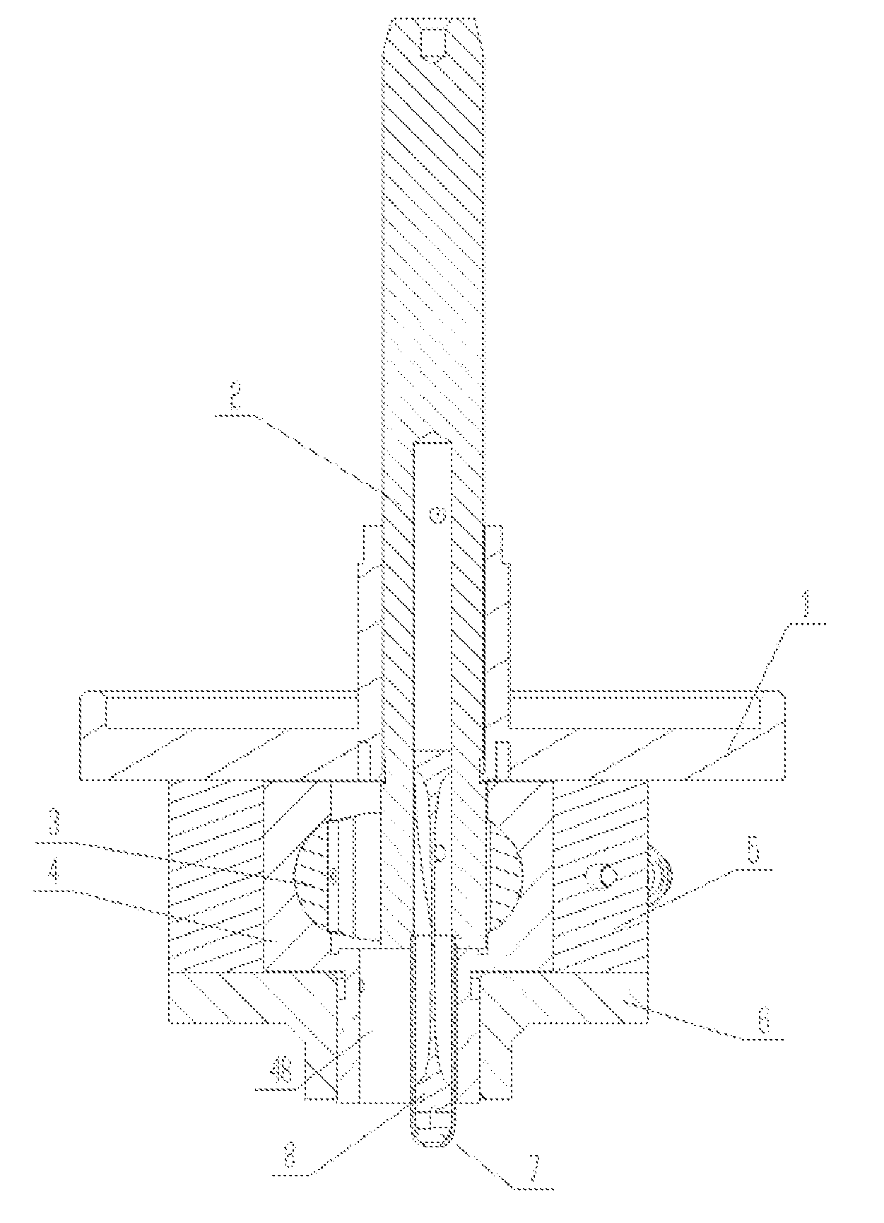
[0021] FIG. 1 is a schematic diagram illustrating an exploded state of a rotary cylinder piston compressor pump according to a first specific embodiment of the present disclosure;
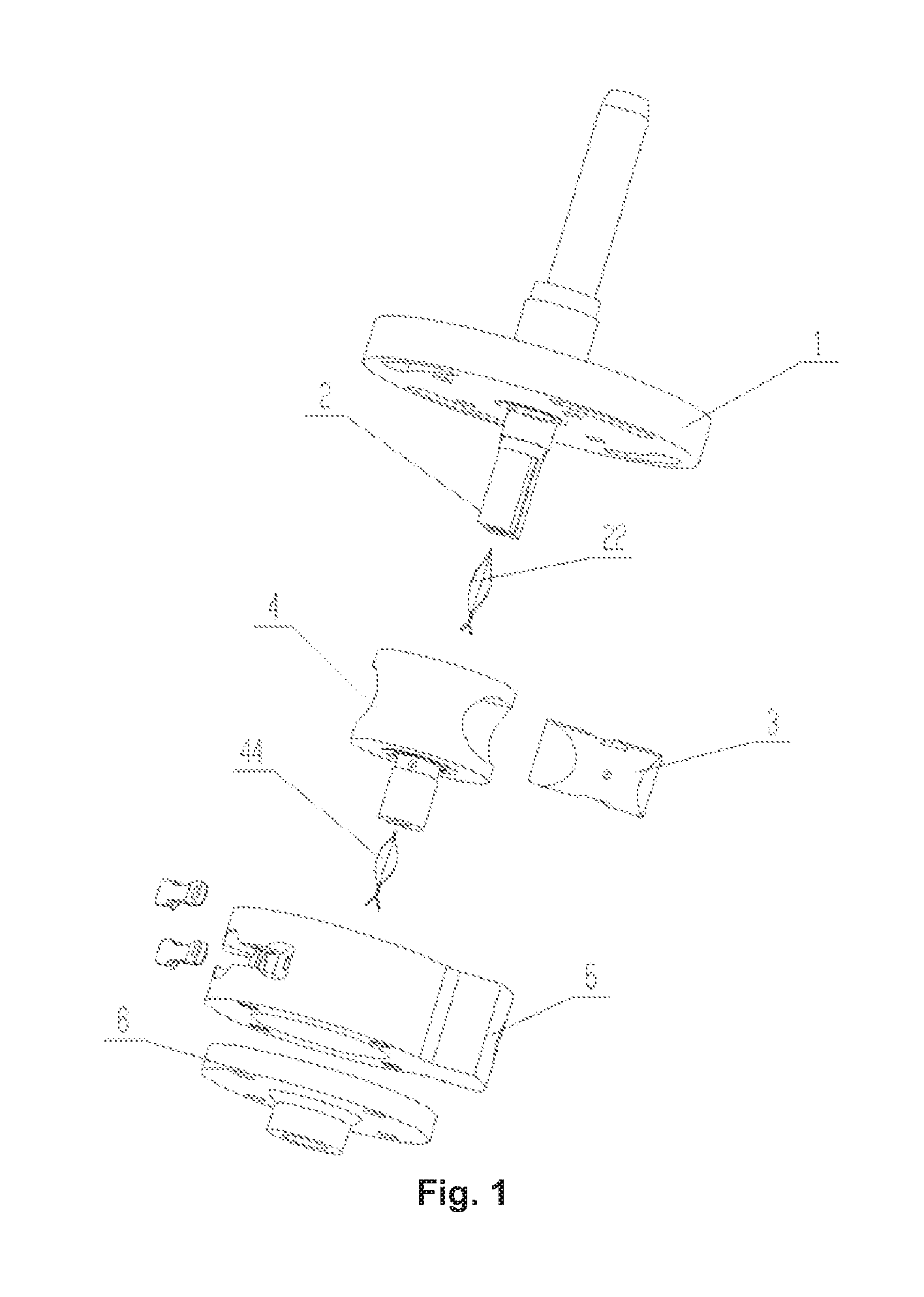
[0022] FIG. 2 is a schematic structure diagram of a rotary cylinder piston corepressor pump according to a first embodiment of the present disclosure;
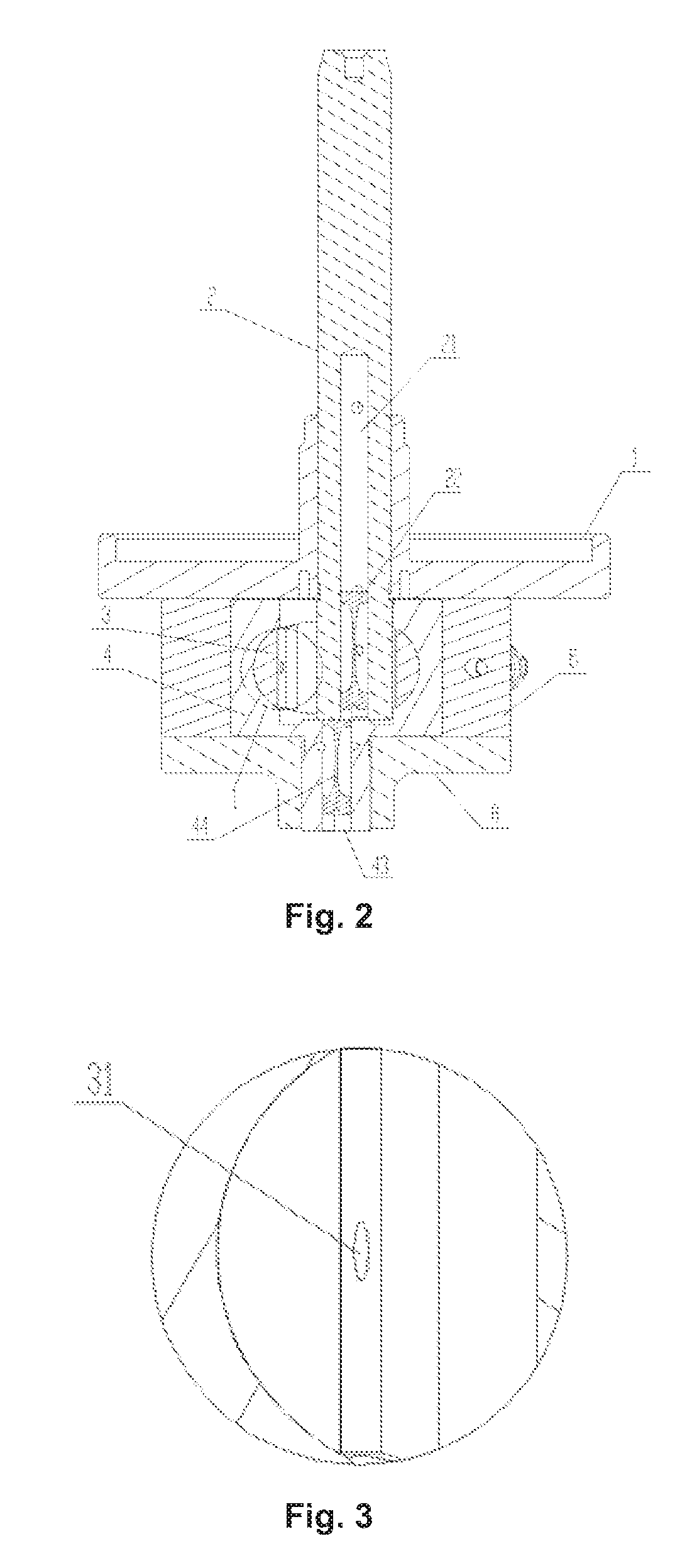
[0023] FIG. 3 is a partial enlarged view of "part I" in FIG. 2;
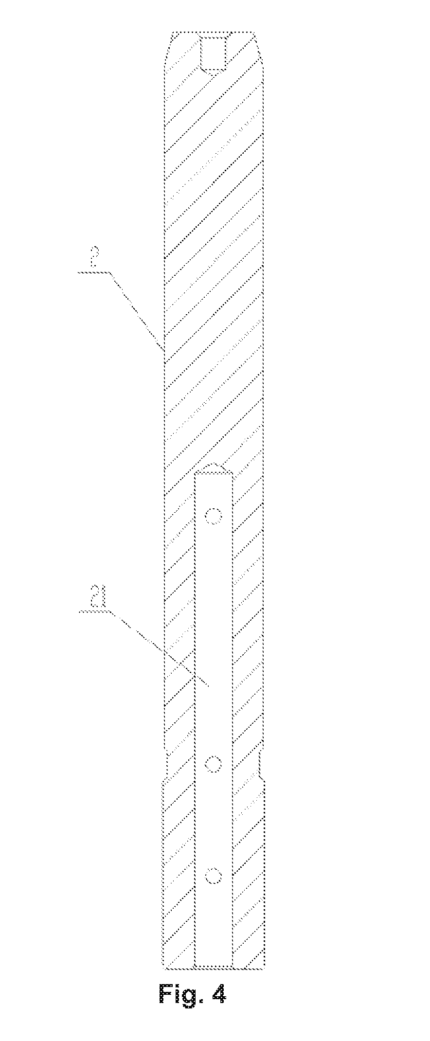
[0024] FIG. 4 is a schematic structure diagram of a rotating shaft according to a first embodiment of the present disclosure;
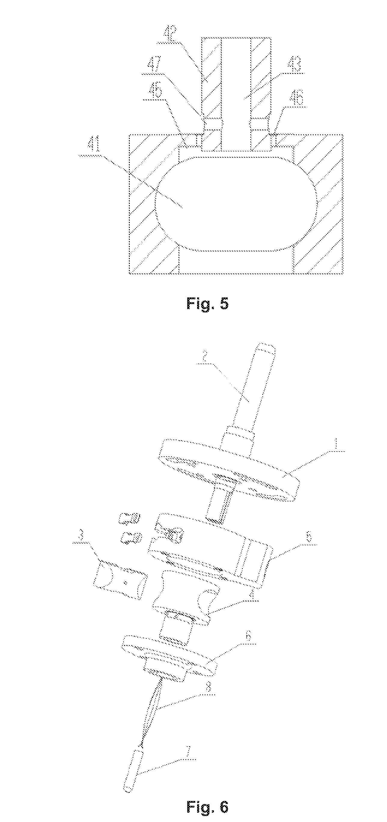
[0025] FIG. 5 is a schematic structure diagram of a cylinder according to a first embodiment of the present disclosure;
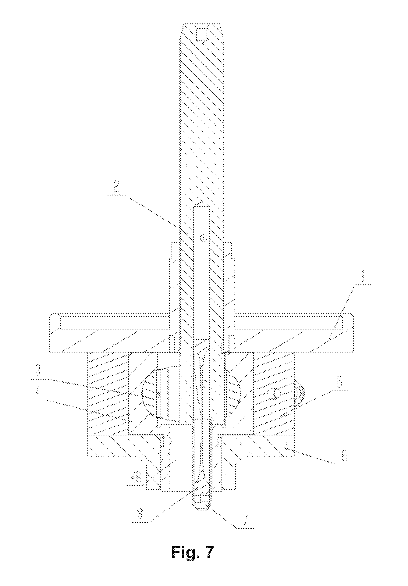
[0026] FIG. 6 is a schematic diagram illustrating an exploded state of a rotary cylinder piston compressor pump according to a second embodiment of the present disclosure;
[0027] FIG. 7 is a schematic structure diagram of a rotary cylinder piston compressor pump according to a second embodiment of the present disclosure;
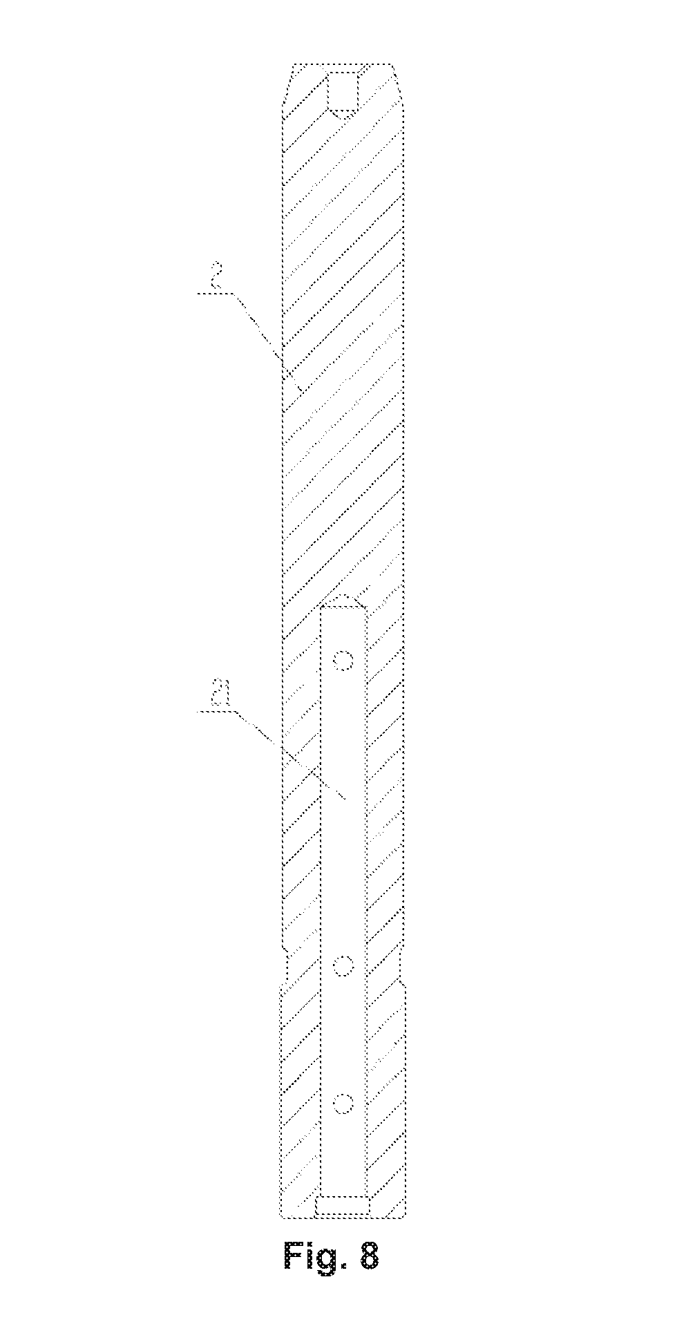
[0028] FIG. 8 is a schematic structure diagram of a rotating shaft according to a second embodiment of the present disclosure;
[0029] FIG. 9 is a schematic structure diagram of a cylinder according to a second embodiment of the present disclosure; and
[0030] FIG. 10 is a schematic structure diagram of a cross slider.
[0031] 1: Upper flange; 2: rotating shaft; 3: piston; 4: cylinder; 5: cylinder sleeve; 6: lower flange; 7: oil guiding pipe; 8: oil guiding sheet;
[0032] 21: rotating shaft hole; 22: rotating shaft hole oil guiding sheet;
[0033] 31: piston oil hole;
[0034] 41: piston hole; 42: cylinder short shaft; 43: cylinder hole; 44: cylinder hole oil guiding sheet; 45: recess; 46: cylinder oil hole; 47: cylinder short shaft hole; 48: through hole structure.
DETAILED DESCRIPTION OF THE EMBODIMENTS
[0035] The technical solutions of the present disclosure will be further described below in conjunction with the accompanying drawings and specific implementations.
First Embodiment
[0036] As shown in FIG. 1 to FIG. 5, the present embodiment provides a rotary cylinder piston compressor pump. The rotary cylinder piston compressor pump includes an upper flange 1, a rotating shaft 2, a piston 3, a cylinder 4, a cylinder sleeve 5, and a lower flange 6, wherein the piston 3 is mounted in a piston hole 41 of the cylinder 4, a cylinder short shaft 42 of the cylinder 4 is mounted on the lower flange 6, the cylinder sleeve 5 is mounted coaxially with the cylinder 4, the lower flange 6 is fixed at the lower end of the cylinder sleeve 5, a piston bearing surface of the rotating shaft 2 is fitted with a piston plane, the upper flange 1 fixes the upper half of the rotating shaft 2, and the upper flange 1 is fixed to the upper end of the cylinder sleeve 5 by screws.
[0037] Specifically, a rotating shaft hole 21 is provided in the rotating shaft 2, and an oil guiding channel communicated with the rotating shaft hole 21 is provided in the cylinder 4.
[0038] Referring to FIG. 2 and FIG. 5, a recess 45 is formed in the inner end face of the cylinder 4, an oil path sealed relative to a compression cavity of the cylinder 4 is formed between the recess 45 and the piston 3, the oil path is communicated with an oil path between the piston 3 and the rotating shaft 2 and is communicated with the oil guiding channel by means of an oil returning channel. Specifically, referring to FIG. 5, the recess 45 is an annular oil groove provided around the cylinder short shaft 42, and the provision of the recess 45 does not affect the air tightness between the cylinder short shaft 42 and the rotating shaft 2.
[0039] By providing the recess 45 and the oil returning channel, the oil discharging resistance of an oil hole in the side surface of the rotating shaft 2 is reduced, the oil discharging quantity of the oil hole of the rotating shaft 2 is increased, and therefore, the problem of abnormal abrasion caused by insufficient lubrication between the side surface of the rotating shaft 2 and the piston 3 under a heavy working condition is effectively solved.
[0040] The oil returning channel includes a cylinder oil hole 46 provided on the cylinder 4, and the cylinder oil hole 46 penetrates through the bottom of the recess 45 and the outer surface of the cylinder 4.
[0041] The oil returning channel further includes a cylinder short shaft hole 47 provided on the cylinder short shaft 42, the cylinder short shaft hole 47 is communicated with the cylinder oil hole 46, and the cylinder short shaft hole 47 penetrates through the inner surface and the outer surface of the cylinder short shaft 42.
[0042] By providing the recess 45, the cylinder oil hole 46 and the cylinder short shaft hole 47, the oil discharging resistance of the oil hole in the side surface of the rotating shaft 2 is further reduced, the oil discharging quantity of the oil hole of the rotating shaft 2 is increased, and therefore, the problem of abnormal abrasion caused by insufficient lubrication between the side surface of the rotating shaft 2 and the piston 3 under a heavy working condition is effectively solved.
[0043] An intersection area of the rotating shaft hole 21 and the oil guiding channel is not less than 20% of a cross-sectional area of the rotating shaft hole 21. By increasing the intersection area of the rotating shaft hole 21 and the oil guiding channel, the oil pumping amount of the rotating shaft 2 is able to be increased.
[0044] A specific means of increasing the intersection area of the rotating shaft hole 21 and the oil guiding channel is to increase the diameter of the rotating shaft hole 21 of the rotating shaft 2. Preferably, the ratio of the inner diameter of the rotating shaft hole 21 to the outer diameter of the rotating shaft 2 ranges from 0.3 to 0.6. Further preferably, the ratio of the inner diameter of the rotating shaft hole 21 to the outer diameter of the rotating shaft 2 is 0.35, 0.4 or 0.5. In the present embodiment, the inner diameter of the rotating shaft hole 21 is 6 mm, and the outer diameter of the rotating shaft 2 is 16.5 mm.
[0045] Referring to FIG. 2, in the present embodiment, the cylinder 4 includes a cylinder short shaft 42, and the oil guiding channel is a cylinder hole 43 provided in the cylinder short shaft 42. The cylinder hole 43 is provided with a cylinder hole oil guiding sheet 44. The cylinder hole oil guiding sheet 44 rotates in synchronism with the cylinder 4 and pumps oil into the rotating shaft hole 21 by a centrifugal force. Preferably, an intersection area of the rotating shaft hole 21 and the cylinder hole 43 is not less than one-third or one-fifth of the cross-sectional area of the rotating shaft hole 21.
[0046] Referring to FIG. 1 and FIG. 2, in order to further increase the oil pumping amount of the rotating shaft 2, a rotating shaft hole oil guiding sheet 22 is disposed in the rotating shaft hole 21. The rotating shaft hole oil guiding sheet 22 has the same structure as the conventional cylinder hole oil guiding sheet 44 disposed in the cylinder hole 43, and has a spiral blade type structure.
[0047] A piston oil hole 31 penetrating through the inner surface and the outer surface of the piston 3 is provided on the side wall of the piston 3. The piston oil hole 31 can lubricate the outer wall surface of the piston 3 and the inner wall surface of the cylinder 4 while reducing the oil loss caused by the reciprocating motion of the rotating shaft 2 in the piston hole.
[0048] The inlet end of the rotating shaft hole 21 is a tapered structure flared outward. By arranging the end portion of the rotating shaft hole 21 into a tapered structure, an intersection area of the rotating shaft hole 21 and the oil guiding channel can be effectively increased under the premise of the same hole diameter of the rotating shaft hole 21.
[0049] In order to further explain the above rotary cylinder piston compressor pump, the present embodiment also provides the working process of the above pump:
[0050] A motor drives the rotating shaft 2 to rotate, and the piston supporting surface of the rotating shaft 2 drives the piston 3 to rotate, but the piston 3 only reciprocates relative to the rotating shaft 2; the non-circular (or circular) side of the piston further drives the cylinder 4 to rotate, at this time, the piston 3 only reciprocates relative to the cylinder 4, and the reciprocating direction of the piston 3 to the cylinder 4 is perpendicular to the reciprocating direction of the piston 3 to the rotating shaft 2; during the reciprocating motion, the entire pump structure completes the process of suction, compression and exhaust.
[0051] The present embodiment also provides a compressor, which includes the rotary cylinder piston compressor pump as described above.
Second Embodiment
[0052] As shown in FIG. 6 to FIG. 9, in the present embodiment, another structural form of an oil guiding channel is provided. Referring to FIG. 6 and FIG. 7, the oil guiding channel is an oil guiding pipe 7. The cylinder 4 includes a cylinder short shaft 42, the cylinder short shaft 42 is provided with a through hole structure 48 for providing a moving space for movement of the oil guiding pipe 7, and the oil guiding pipe 7 is disposed in the through hole structure 48. One end of the oil guiding pipe 7 is mounted on the rotating shaft 2, the outlet end of the oil guiding pipe 7 is butted with the rotating shaft hole 21, and an oil guiding sheet 8 is disposed in the oil guiding pipe 7. The structure of the oil guiding sheet is the same as that of the rotating shaft oil guiding sheet 22 mentioned in the first embodiment.
[0053] In order to provide a moving space for the oil guiding pipe 7, the inner diameter of the cylinder short shaft 42 is larger than the inner diameter of the cylinder short shaft 42 in the first embodiment, and the corresponding inner diameter of a bearing on a lower flange 6 is also increased. Specifically, the ratio of the inner diameter of the through hole structure 48 to the outer diameter of the cylinder short shaft 42 ranges from 0.6 to 0.8. Preferably, the ratio of the inner diameter of the through hole structure 48 to the outer diameter of the cylinder short shaft 42 is 0.65, 0.7 or 0.75. In the present embodiment, the inner diameter of the through hole structure 48 is 14 mm, and the outer diameter of the cylinder short shaft 42 is 20 mm.
[0054] One end of the oil guiding pipe 7 is inserted into the rotating shaft hole 21, and the end portion of the rotating shaft hole 21 is arranged in a tapered structure. When the oil guiding pipe 7 is assembled into the rotating shaft hole 21, the tapered structure can play a guiding role, which is convenient for assembly of the oil guiding pipe 7. Referring to FIG. 8, the lower end of the rotating shaft hole 21 is a stepped hole for inserting the oil guiding pipe 7. By using the oil guiding pipe 7 as the oil guiding channel, the intersection area of the rotating shaft hole 21 and the oil guiding channel can be made the same as the cross-sectional area of the rotating shaft hole 21, whereby the oil pumping effect of the rotating shaft 2 can be remarkably improved.
[0055] It is to be noted that in this embodiment, other structures are the same as that of the first embodiment except that the structural form of the oil guiding channel is different from that of the first embodiment.
[0056] The technical principles of the present disclosure have been described above in connection with specific embodiments. The descriptions are only intended to explain the principles of the present disclosure and are not to be construed as limiting the scope of protection of the present disclosure. Based on the explanation herein, those skilled in the art can associate other specific implementations of the present disclosure without making creative works. These modes fall within the scope of protection of the present disclosure.
* * * * *
D00000
D00001
D00002
D00003
D00004
D00005
D00006
D00007
XML
uspto.report is an independent third-party trademark research tool that is not affiliated, endorsed, or sponsored by the United States Patent and Trademark Office (USPTO) or any other governmental organization. The information provided by uspto.report is based on publicly available data at the time of writing and is intended for informational purposes only.
While we strive to provide accurate and up-to-date information, we do not guarantee the accuracy, completeness, reliability, or suitability of the information displayed on this site. The use of this site is at your own risk. Any reliance you place on such information is therefore strictly at your own risk.
All official trademark data, including owner information, should be verified by visiting the official USPTO website at www.uspto.gov. This site is not intended to replace professional legal advice and should not be used as a substitute for consulting with a legal professional who is knowledgeable about trademark law.