Thermal Barrier For Downhole Flasked Electronics
RAFIE; SAEED ; et al.
U.S. patent application number 15/954176 was filed with the patent office on 2019-10-17 for thermal barrier for downhole flasked electronics. This patent application is currently assigned to Baker Hughes, a GE company, LLC. The applicant listed for this patent is Baker Hughes, a GE company, LLC. Invention is credited to RICHARD E. BAILEY, SAEED RAFIE.
| Application Number | 20190316442 15/954176 |
| Document ID | / |
| Family ID | 68161481 |
| Filed Date | 2019-10-17 |


| United States Patent Application | 20190316442 |
| Kind Code | A1 |
| RAFIE; SAEED ; et al. | October 17, 2019 |
THERMAL BARRIER FOR DOWNHOLE FLASKED ELECTRONICS
Abstract
Apparatus including an assembly associated with a downhole tool and configured to thermally isolate a thermally sensitive component. Components of the assembly include a thermal housing; a chassis interior to the thermal housing; at least one thermally sensitive component mounted on the chassis; and a thermal isolation support connecting the chassis to the tool. The thermal isolation support comprises an elongated thermal isolator having a first end and a second end opposite the first end, the thermal isolator connected to the tool at the first end and connected to the chassis at the second end, and a heat sink thermally coupled to the elongated thermal isolator at the second end. The second end of the elongated thermal isolator may comprise the only points of thermal coupling between the heat sink and the components other than the heat sink.
| Inventors: | RAFIE; SAEED; (Houston, TX) ; BAILEY; RICHARD E.; (The Woodlands, TX) | ||||||||||
| Applicant: |
|
||||||||||
|---|---|---|---|---|---|---|---|---|---|---|---|
| Assignee: | Baker Hughes, a GE company,
LLC Houston TX |
||||||||||
| Family ID: | 68161481 | ||||||||||
| Appl. No.: | 15/954176 | ||||||||||
| Filed: | April 16, 2018 |
| Current U.S. Class: | 1/1 |
| Current CPC Class: | E21B 47/017 20200501; E21B 36/001 20130101 |
| International Class: | E21B 36/00 20060101 E21B036/00; E21B 47/01 20060101 E21B047/01 |
Claims
1. An apparatus for use in a borehole intersecting an earth formation, the apparatus comprising: an assembly associated with a downhole tool and configured to thermally isolate a thermally sensitive component, the assembly comprising components including: a thermal housing; a chassis interior to the thermal housing; at least one thermally sensitive component mounted on the chassis; a thermal isolation support connecting the chassis to the tool, wherein the thermal isolation support comprises: an elongated thermal isolator having a first end and a second end opposite the first end, the thermal isolator connected to the tool at the first end and connected to the chassis at the second end, and a heat sink thermally coupled to the elongated thermal isolator at the second end.
2. The apparatus of claim 1, wherein the second end of the elongated thermal isolator comprises the only points of thermal coupling between the heat sink and the components other than the heat sink.
3. The apparatus of claim 1, wherein a center of mass of the heat sink is oriented further from the thermally sensitive component than the second end.
4. The apparatus of claim 1, wherein the heat sink is elongated and comprises: a coupled end coupled to the second end of the elongated thermal isolator, and a decoupled end opposite the coupled end, the decoupled end thermally decoupled from the elongated thermal isolator.
5. The apparatus of claim 4, wherein the decoupled end is oriented further from the thermally sensitive component than the coupled end.
6. The apparatus of claim 4, wherein the decoupled end is located proximate the first end of the elongated thermal isolator.
7. The apparatus of claim 1, wherein the elongated thermal isolator comprises a sleeve.
8. The apparatus of claim 1, wherein the heat sink is interior to the elongated thermal isolator.
9. The apparatus of claim 1, wherein a length of the heat sink is substantially the same as a length of the elongated thermal isolator.
10. The apparatus of claim 1, wherein the heat sink is a substantially solid cylinder.
11. The apparatus of claim 1, wherein the at least one thermally sensitive component comprises at least one downhole electronic component.
12. The apparatus of claim 1, wherein the chassis is supported substantially exclusively by the thermal isolation support.
13. The apparatus of claim 1, wherein the heat sink is thermally coupled to the elongated thermal isolator only at the second end.
14. The apparatus of claim 1, wherein the elongated thermal isolator comprises a mesh tube of connected members.
15. An apparatus for use in a borehole intersecting an earth formation, the apparatus comprising: an assembly associated with a downhole tool and configured to thermally isolate a thermally sensitive component, the assembly comprising components including: a thermal housing; a chassis interior to the thermal housing; at least one thermally sensitive component mounted on the chassis; a thermal isolation support connecting the chassis to the tool, wherein the thermal isolation support comprises: an elongated thermal isolator having a first end and a second end opposite the first end, the thermal isolator connected to the tool at the first end and connected to the chassis at the second end, and wherein the elongated thermal isolator comprises a mesh tube of connected members.
16. The apparatus of claim 15, wherein the thermal isolation support comprises a heat sink thermally coupled to the elongated thermal isolator at the second end.
17. The apparatus of claim 15, wherein a majority of the connected members of the mesh tube are substantially non-parallel with a longitudinal axis of the downhole tool.
Description
FIELD OF THE DISCLOSURE
[0001] In one aspect, this disclosure relates generally to thermally isolating heat sensitive components used in downhole applications in a borehole in an earth formation.
BACKGROUND OF THE DISCLOSURE
[0002] Drilling wells for various purposes is well-known. Such wells may be drilled for geothermal purposes, to produce hydrocarbons (e.g., oil and gas), to produce water, and so on. Well depth may range from a few thousand feet to 25,000 feet or more. Downhole tools, used during and after drilling, often incorporate various sensors, instruments and control devices in order to carry out any number of downhole operations. Thus, the tools may include sensors and/or electronics for formation evaluation, fluid analysis, monitoring and controlling the tool itself, and so on.
[0003] Borehole temperatures can vary from ambient up to about 500.degree. F. (260.degree. C.) and pressures from atmospheric up to about 30,000 psi (206.8 mega pascals). Temperature and pressure conditions such as these can have an adverse effect on instruments used downhole. Heat especially can be undesirable for tools having electronic components. Elevated temperatures in the borehole ("downhole heat") may cause thermally sensitive electronic components to work inaccurately or even fail.
[0004] One historical method for dealing with downhole heat is to avoid it. For example, it is known in the art that a system that includes a plurality of temperature sensors distributed in an oil well in the wellbore where at least some of the sensors are in a heat affected zone can be monitored using a downhole processor positioned proximate and substantially outside of the heat affected zone to receive and digitize temperature measurements. Elevated temperature (or "hot") conditions, as referred to herein may be defined as an ambient temperature which compromises or impairs the structural integrity, operating efficient, operating life, or reliability of a given tool, device, or instrument.
[0005] Other methods of dealing with downhole heat are also known. Available techniques may include eliminating the incoming heat to the system and cooling the heat sensitive components using either active or passive cooling methods. Due to the nature of the operation, since the earth temperature gets hotter as true depth increases, the first option is not feasible. A tool configured for either active or passive cooling may operate in a hot downhole environment, including logging and drilling operations.
SUMMARY OF THE DISCLOSURE
[0006] Aspects of the disclosure include apparatus for use in a borehole intersecting an earth formation. The apparatus may comprise an assembly associated with a downhole tool and configured to thermally isolate a thermally sensitive component. The assembly may comprise components including: a thermal housing; a chassis interior to the thermal housing; at least one thermally sensitive component mounted on the chassis; and a thermal isolation support connecting the chassis to the tool. The chassis may be supported substantially exclusively by the thermal isolation support. The thermal isolation support may comprise an elongated thermal isolator having a first end and a second end opposite the first end, the thermal isolator connected to the tool at the first end and connected to the chassis at the second end; and a heat sink thermally coupled to the elongated thermal isolator at the second end.
[0007] The second end of the elongated thermal isolator may comprise the only points of thermal coupling between the heat sink and the components other than the heat sink. A center of mass of the heat sink may be oriented further from the thermally sensitive component than the second end. The heat sink may be interior to the elongated thermal isolator.
[0008] The heat sink may be thermally coupled to the elongated thermal isolator only at the second end. The heat sink may be elongated and comprise a coupled end coupled to the second end of the elongated thermal isolator and a decoupled end opposite the coupled end, with the decoupled end thermally decoupled from the elongated thermal isolator. The decoupled end may be oriented further from the thermally sensitive component than the coupled end. The decoupled end may be located proximate the first end of the elongated thermal isolator.
[0009] The elongated thermal isolator may comprise a sleeve. The length of the heat sink may be substantially the same as the length of the elongated thermal isolator. The heat sink maybe a substantially solid cylinder. The at least one thermally sensitive component may comprise at least one downhole electronic component. The elongated thermal isolator may comprise a mesh tube of connected members.
[0010] In other general embodiments, the apparatus comprises an assembly associated with a downhole tool and configured to thermally isolate a thermally sensitive component. The assembly comprises components including: a thermal housing; a chassis interior to the thermal housing; at least one thermally sensitive component mounted on the chassis; and a thermal isolation support connecting the chassis to the tool. The thermal isolation support comprises an elongated thermal isolator having a first end and a second end opposite the first end, the thermal isolator connected to the tool at the first end and connected to the chassis at the second end. The elongated thermal isolator may comprise a mesh tube of connected members. The thermal isolation support may comprise a heat sink thermally coupled to the elongated thermal isolator at the second end. A majority of the connected members of the mesh tube may be substantially non-parallel with a longitudinal axis of the downhole tool.
[0011] Examples of some features of the disclosure may be summarized rather broadly herein in order that the detailed description thereof that follows may be better understood and in order that the contributions they represent to the art may be appreciated.
BRIEF DESCRIPTION OF THE DRAWINGS
[0012] For a detailed understanding of the present disclosure, reference should be made to the following detailed description of the embodiments, taken in conjunction with the accompanying drawings, in which like elements have been given like numerals, wherein:
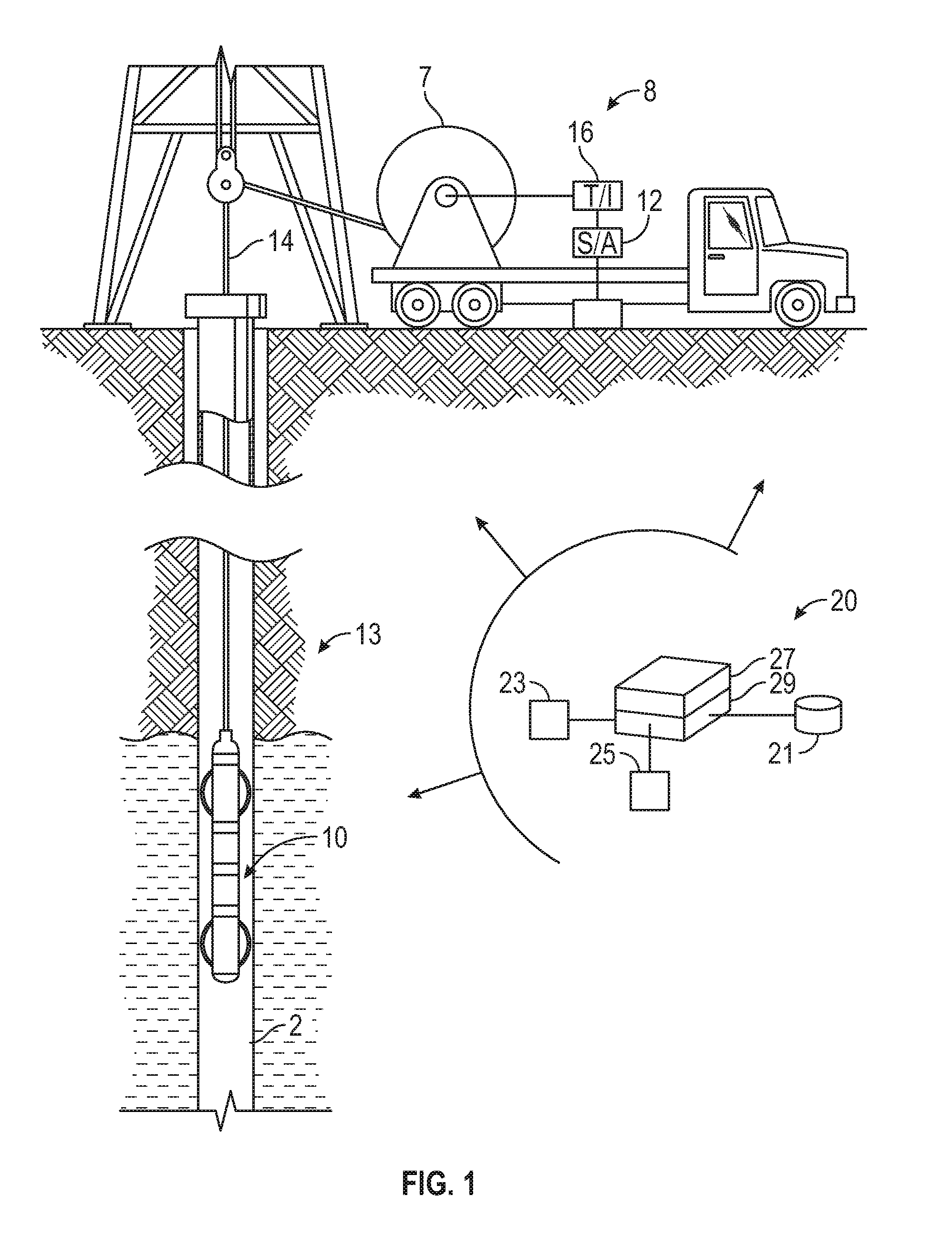
[0013] FIG. 1 shows a schematic diagram illustrating downhole tool systems in accordance with embodiments of the present disclosure;
[0014] FIG. 2 illustrates example assemblies for isolating an electronics package from heat;
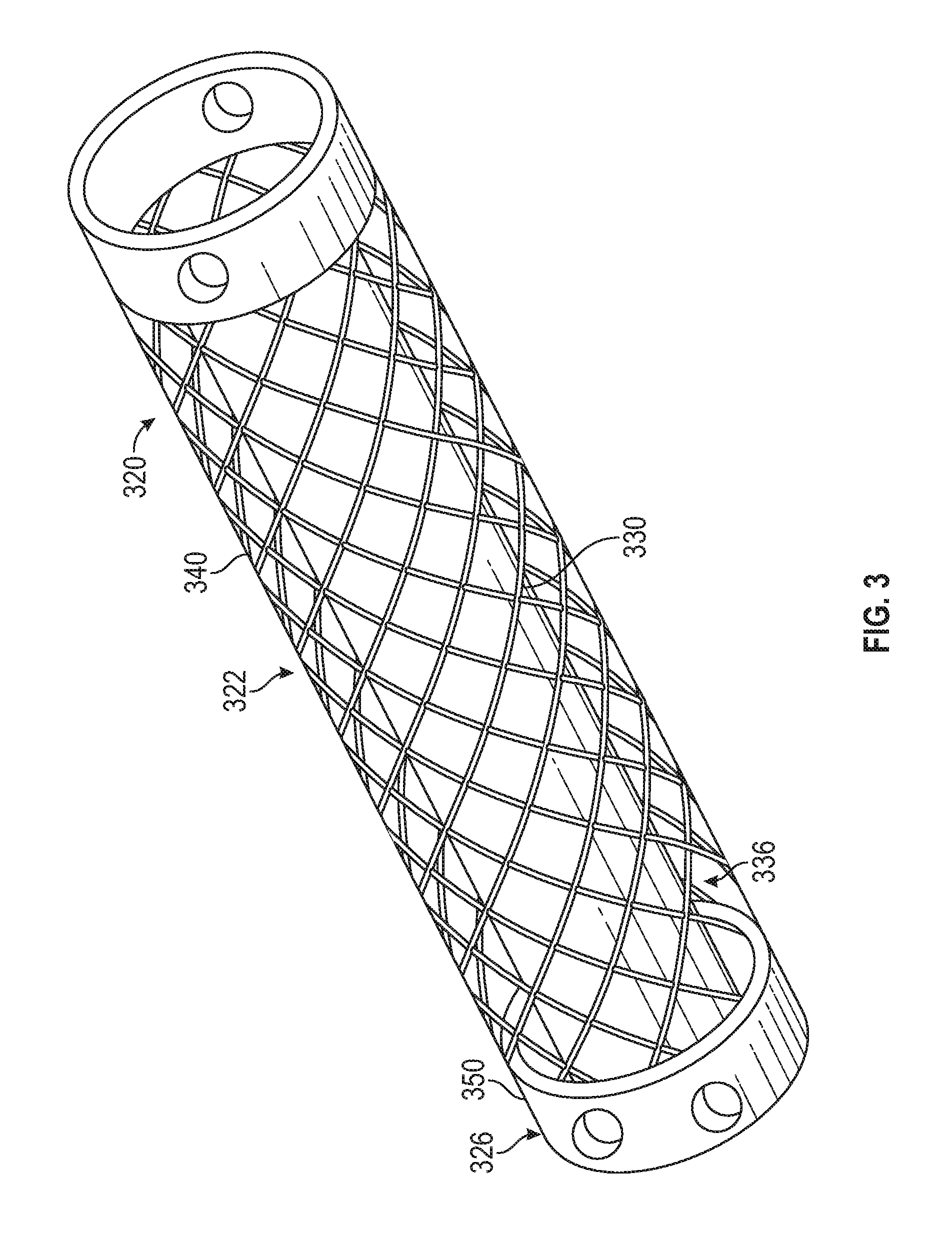
[0015] FIG. 3 shows a perspective view of an example thermal isolation support in accordance with embodiments of the present disclosure;
[0016] FIG. 4 shows a schematic tool diagram illustrating additional assemblies in accordance with embodiments of the present disclosure.
DETAILED DESCRIPTION
[0017] Aspects of the present disclosure relate to thermally isolating a thermally sensitive component in a tool downhole from a high-temperature environment. The present disclosure relates to devices and methods isolating heat sensitive components from a wellbore environment and/or heat generated by downhole components. In particular, aspects of the disclosure relate to flask-type thermal isolation systems. Aspects include apparatus for investigating a borehole or other use in a borehole intersecting an earth formation.
[0018] Aspects of the present disclosure provide a novel way of thermally isolating electronics inside downhole drilling or logging tools. Embodiments disclosed herein may include an assembly associated with a downhole tool and configured to thermally isolate a thermally sensitive component. The assembly may include a thermal housing; a chassis interior to the thermal housing; at least one thermally sensitive component mounted on the chassis; and a thermal isolation support connecting the chassis to the tool. In aspects, the present disclosure includes apparatuses related to drilling a borehole in an earth formation, performing well logging in a borehole intersecting an earth formation, and so on.
[0019] The thermal isolation support may include an elongated thermal isolator having a first end and a second end opposite the first end, the thermal isolator connected to the tool at the first end and connected to the chassis at the second end; and a heat sink thermally coupled to the elongated thermal isolator at the second end. The thermal isolator and heat sink may be integrated. The heat sink may be thermally decoupled from the elongated thermal isolator proximate the first end. Thus, the heat sink is thermally isolated from the elongated thermal isolator proximate the first end. The second end of the elongated thermal isolator may be the only points of thermal coupling between the heat sink and the components of the assembly other than the heat sink. A center of mass of the heat sink may be oriented further from the thermally sensitive component than the second end.
[0020] Thus, the elongated thermal isolator experiences a graduated elevation in temperature along its length as the tool is exposed to elevated temperatures, with the first end experiencing greater changes in temperature (and more quickly) than the second end. The heat sink coupled at the second end functions as a spillover reservoir for environmental heat absorbed by the elongated thermal isolator, by efficiently absorbing thermal energy at the second end of the isolator and thereby vastly reducing thermal energy absorbed by the chassis.
[0021] The term "thermally sensitive component" (or "heat sensitive component") shall hereinafter be used to refer to any tool, electrical component, sensor, electronic instrument, structure, or material that degrades either in performance or in integrity when exposed to temperatures above 200 degrees centigrade. For purposes of discussion, a wellbore may be considered "hot" if the ambient temperature compromises or impairs the structural integrity, operating efficient, operating life, or reliability of a given tool, device, or instrument.
[0022] Techniques described herein are particularly suited for use in measurement of values of properties of a formation downhole or of a downhole fluid while drilling, through the use of instruments which may utilize components as described herein, or otherwise for use in conducting operations downhole. These values may be used to evaluate and model the formation, the borehole, and/or the fluid, and for conducting further operations in the formation or the borehole.
[0023] Conventionally, Dewar vacuum-type flasks (e.g., AWS flask- or NKW flask-style housing) are used to protect the heat sensitive components from high downhole temperatures for a short period of time (e.g., approximately 8-10 hours). Although, these flasks provide a thermal barrier, some undesirable external heat can leak into the flask. The traditional thermal isolators are designed based on a slotted tube filled with felt. This slotted-tube design provided a tortuous path for the heat to reach sensitive components. In addition to the improved heat sink configuration, a thermal isolator in accordance with embodiments of the present disclosure may be implemented in the form of a meshed tube or cylinder. The heat sink may be inserted inside the tube (e.g., the heat sink may be encircled by the cylinder), so the new thermal isolator is shorter and more efficient than the existing thermal isolators.
[0024] Referring to FIG. 1, a wireline well logging tool 10 is shown being lowered into a wellbore 2 penetrating earth formations 13. The tool 10 may be lowered into the wellbore 2 and withdrawn therefrom by a carrier 14 (e.g., an armored electrical cable). In one embodiment, circuitry associated with the tool may be configured to take measurements using instruments associated with the tool as the tool moves along the longitudinal axis of the borehole (`axially`). The cable 14 can be spooled by a winch 7 or similar device known in the art. The cable 14 may be electrically connected to a surface recording system 8 of a type known in the art which can include a signal decoding and interpretation unit 16 and a recording unit 12. Signals transmitted by the logging tool 10 along the cable 14 can be decoded, interpreted, recorded and processed by the respective units in the surface system 8.
[0025] Systems in accordance with the present disclosure may alternatively include a conventional derrick and a conveyance device, which may be rigid or non-rigid, which may be configured to convey the downhole tool 10 in the wellbore. Drilling fluid (`mud`) may be present in the borehole. The carrier may be a drill string, coiled tubing, a slickline, an e-line, a wireline, etc. Downhole tool 10 may be coupled or combined with additional tools, including, e.g., some or all the information processing system as implemented by hardware environment 20. Thus, depending on the configuration, the tool 10 may be used during drilling and/or after the wellbore has been formed. While a land system is shown, the teachings of the present disclosure may also be utilized in offshore or subsea applications. The carrier may include a bottom hole assembly, which may include a drilling motor for rotating a drill bit.
[0026] Aspects of the present disclosure are subject to application in various different embodiments. In some general embodiments, the carrier is implemented as a tool string of a drilling system, and the acoustic wellbore logging may be characterized as "logging-while-drilling" (LWD) or "measurement-while-drilling" (MWD) operations.
[0027] The toolstring as well as the logging tool may include thermally sensitive components. Such components include those that incorporate transistors, integrated circuits, resistors, capacitors, and inductors, as well as electronic components such as sensing elements, including accelerometers, magnetometers, photomultiplier tubes, and strain gages. The thermal isolation systems provided by the present disclosure, such as those shown in the Figures, may be utilized to protect these components from the hot wellbore environment. The toolstring may also include communication devices, transmitters, repeaters, processors, power generation devices, or other devices that may incorporate heat sensitive components. In many applications, the drilling system may be operated for well over eight hours downhole.
[0028] Conventional systems for thermal isolation are known. One type of conventional system employs a container designed to protect heat sensitive components from high temperature environments, such as a Dewar-like vacuum flask. The sensitive components may be positioned within the container and conveyed into a wellbore. The container may be directly inserted into a wellbore tool string, or may be positioned in a housing (e.g., a sub, a module or other suitable structure). The container provides a thermal barrier that isolates heat sensitive components from ambient wellbore temperatures. The container may employ a conventional double wall construction with an interstitial vacuum typical of Dewar flasks, but may be of any suitable configuration that prevents or reduces heat transfer from the downhole environment to the electronics package.
[0029] More recently, an improved thermal isolation device, described in U.S. Pat. No. 7,440,283 to Rafie, commonly owned with the present application and incorporated herein by reference in its entirety, includes one or more heat sinks and a thermal isolator. The thermal isolator mechanically connects an assembly including the internal components to the container. The heat sinks are positioned in a chain between the isolator and electronic components. Traditionally, heat sinks provide thermal storage by diverting heat flow away from heat sensitive components. A first heat sink may be configured to absorb heat primarily from an electronics package and a second heat sink may be configured to primarily absorb heat applied by the wellbore environment. The heat sinks may be configured to have the same thermal response or different thermal responses or absorb the same or different amounts of heat (e.g., a stepped thermal response or a graduated thermal response). It should be noted that the heat sinks of Rafie are connected in a linear fashion, such that the heat sink operatively closest to the container heats up first and the furthermost position of the heat sink (which experiences the latest temperature increase) is proximate the chassis housing the electronic components.
Improved Thermal Isolation for Vacuum-Flask Type Isolation Systems
[0030] General embodiments of the present disclosure may include a tool for performing well logging in a borehole intersecting an earth formation. Aspects of the present disclosure may be utilized to increase temperature survival time of downhole tools and thereby increase the time heat sensitive equipment may be deployed in a wellbore. As will be appreciated, the present invention is susceptible to embodiments of different forms. There are shown in the drawings, and herein will be described in detail, specific embodiments of the present invention with the understanding that the present disclosure is to be considered an exemplification of the principles of the invention, and is not intended to limit the invention to that illustrated and described herein. Further, while embodiments may be described as having one or more features or a combination of two or more features, such a feature or a combination of features should not be construed as essential unless expressly stated as essential.
[0031] FIG. 2 shows a schematic tool diagram illustrating assemblies in accordance with embodiments of the present disclosure. FIG. 2 illustrates an exemplary assembly 200 for isolating an electronics package 202 from applied heat and/or generated heat. The electronics package 202 may include one or more heat sensitive components 202a and may be mounted on and supported by a chassis 203. In one arrangement, the heat sensitive components 202a communicates with external devices via a cable 204. The components 202a may be positioned within a thermal housing 208 and conveyed into a wellbore. The thermal housing 208 provides a thermal barrier that isolates heat sensitive components from ambient wellbore temperatures.
[0032] The thermal housing 208 may comprise a container 206 positioned within an outer member 209, such as a sub, a module or other suitable structure (e.g., tubular), or may consist of the container or outer member alone. The thermal housing 208 may include multiple containers. In some embodiments, the container 206 may be a Dewar-like vacuum flask employing a conventional double wall construction with an interstitial vacuum typical of Dewar flasks, and the outer member 209 may be a steel tubular that is adapted for conveyance in the borehole and protects the electronics from damage. However, the thermal housing 208 may be of any suitable configuration that prevents or reduces heat transfer from the downhole environment to the electronics package 202.
[0033] As will be discussed in greater detail below, the assembly 200 provides passive cooling for the electronics package 202 by isolating the electronics package 202 from applied heat and/or heat generated from other tool components. The mechanisms for providing thermal isolation include providing a barrier to heat flow and absorbing heat. The thermal housing 208 and other elements of the downhole tool may also cooperate to provide active cooling for the electronics package 202.
[0034] A thermal isolation support 220 connects the chassis 203 to the tool 201. The thermal isolation support 220 mechanically connects the internal components, such as the chassis 203 and electronics package 202 (and, optionally, heat sinks 210) to the container 206. The chassis may be supported substantially exclusively by the thermal isolation support. The chassis 203 may include a metallic plate to support a printed circuit board (PCB), electronics and sensors. The thermal isolation support 220 may include an elongated thermal isolator 222 having a first end 224 and a second end 226 opposite the first end. The thermal isolator 222 is connected to the tool 201 at the first end 224 and connected to the chassis 203 at the second end. The thermal isolator 222 may be made of a material having a relatively low thermal conductivity, such as titanium, or a composite material.
[0035] The thermal isolation support 220 may include a heat sink 230 thermally coupled to the elongated thermal isolator 222 at the second end 226. The heat sink 230 may be elongated, and may be a substantially solid cylinder made of a material having a high thermal capacity, such as copper or stainless steel. The elongated thermal isolator maybe implemented using a sleeve with the heat sink interior to the sleeve. The length of the heat sink 230 may be substantially the same as a length of the elongated thermal isolator 222.
[0036] As described above, the second end 226 of the elongated thermal isolator 222 has the only points of thermal coupling between the heat sink 230 and the components other than the heat sink (e.g., elongated thermal isolator 222, chassis 203, components 202a, container 206). In particular implementations, a center of mass of the heat sink is oriented further from the thermally sensitive component 202a) than the second end 226. Thus, the heat sink may include a coupled end 236 coupled to the second end 226 of the elongated thermal isolator 222, and a decoupled end 234 opposite the coupled end 236. The decoupled end 234 is thermally decoupled from the elongated thermal isolator, and may be oriented further from thermally sensitive components 202a than the coupled end 236. The isolator 222 is configured to minimize axial heat transfer from other tool components to the chassis 203.
[0037] FIG. 3 shows a perspective view of an example thermal isolation support in accordance with embodiments of the present disclosure. The thermal isolation support 320 includes an elongated thermal isolator 322 comprising a mesh tube 340 of connected members (e.g., a mesh sleeve) 340, attached to a base 350 for connection with the tool. All or a portion of the elongated thermal isolator 322 may be generated using additive manufacturing. The spiral mesh structure may be manufactured at an angle to increase the heat path distance through the part. A second end 336 of the heat sink 330 is coupled to the second end 326 of the elongated thermal isolator 322.
[0038] In operation, a considerable temperature difference may develop between the ends of the thermal isolation support 320. While using a sleeve alone may result in the temperature of the sleeve being substantially uniform along the length of the sleeve (e.g., a difference of less than five or ten degrees F. over the length), modeled results for the thermal isolation support 320 of FIG. 3 show differences of 50 degrees F. or more. That is, the end of the support closer to the heat sensitive components increases in temperature more slowly than the end proximate the tool coupling. The lower temperature is desirable in logging instruments to prolong the logging time.
[0039] FIG. 4 shows a schematic tool diagram illustrating additional assemblies in accordance with embodiments of the present disclosure. Tool 401 includes similar features to tool 201. In embodiments, however, the assembly 400 includes one or more additional heat sinks 410. The chassis 403 may also provide a medium to conduct heat from the electronics package 404 to the heat sinks 410 and therefore may be formed of a relatively high thermal conductivity material such as aluminum. The heat sinks 410 may be an object or mass configured to absorb and store thermal energy from internal heat-generating components and/or from the outside environment. Thus, the heat sinks 410 provide thermal isolation by diverting heat flow away from heat sensitive components.
[0040] Heat sinks described herein (e.g., heat sinks 230, 430, 410) may be solid elements or include cavities such as bores. In one embodiment, the heat sinks are made from a eutectic phase changing material, such as bismuth alloys or lead with a high latent heat and low melting temperature. Eutectic materials change phase between their solid and liquid phases at the eutectic temperature (phase change temperature). The eutectic temperature stays substantially constant until the material completely changes the phase. In other embodiments, metals such as stainless steel may be used. The heat sinks may be configured to have the same thermal response or different thermal responses or absorb the same or different amounts of heat. For example, a first heat sink may be configured to have a stepped thermal response and a second heat sink may be configured to have a graduated (gradient) thermal response. Additionally, a first heat sink may be configured to absorb heat primarily from the electronics package and a second heat sink may be configured to primarily absorb a heat applied by the wellbore environment. For instance, the heat sink 430 that is positioned proximate the thermal isolator 422 may be configured to absorb the heat applied by the wellbore environment whereas the heat sink 410 that is positioned distant from the thermal isolation support 420 may be configured to absorb heat from the electronics package 402.
[0041] In one embodiments, the heat sinks may be formed of two or more masses 412 that are separated by spaces 414. In some embodiments, the spaces 414 include air or other gases. In other embodiments, the spaces 414 have a vacuum. In still other embodiments, the spaces 414 include a material having a low thermal conductivity, e.g., felt. Other such materials include nanoporous material. Nanoporous thermal insulating material is available from ASPEN AEROGELS and is commercially available under the trademark "PYROGEL". Nanoporous materials have an open cell structure that provide a relatively high proportion of free void volume (typically greater than 90 percent) compared to conventional solid materials. Their high pore volume, low solid content, and torturous path amorphous structure give rise to lower values for thermal conductivity. Other suitable materials exhibiting low thermal conductivity include ceramics. In one sense, the structure of the heat sink 110 may be described as a segmented body having a plurality of elements formed of material that have high thermal energy absorption properties, each of the plurality of elements being separated by an element having low thermal conductivity.
[0042] In embodiments, the tool 401 includes strategically positioned nanoporous material within the container 406 to reduce heat transfer to the electronics package 402. One exemplary location is between adjacent masses 412. Another is the space between 430 and 422. Another exemplary location is around the heat sinks 410 or otherwise where the nanoporous material reduces heat transfer from the walls of the container 406 to the electronics package 402. Another exemplary location includes open spaces which may otherwise be filled with air, which can be filled with a layer of nanoporous material instead.
[0043] The heat sensitive components associated with the logging tool are protected from the downhole environment using any of the thermal isolation devices previously described in connection with the electronics package 202. The logging tool may be in the wellbore for eight hours or longer. During this time, the tool may be subjected to temperatures in excess of 200 degrees Celsius. Components 202a are initially protected from the high wellbore temperatures by the container 206, 406, which functions as a heat shield or barrier. Heat flow from the thermal isolation support 220 at the end of the container 206 to the container interior is impeded in at least two ways. First, in embodiments where the thermal isolation support 220 is formed of titanium or other material having low thermal conductivity, or is otherwise designed to prevent heat transfer, the thermal isolation support 220 itself impedes heat transfer. Second, the heat sink 230, 330, 430 thermally coupled to the thermal isolation support 220 mitigates heat transferred along the thermal isolation support 220.
[0044] The foregoing description is directed to particular embodiments of the present invention for the purpose of illustration and explanation. It will be apparent, however, to one skilled in the art that many modifications and changes to the embodiment set forth above are possible without departing from the scope of the invention. It is intended that the following claims be interpreted to embrace all such modifications and changes.
[0045] The term "conveyance device" or "carrier" as used above means any device, device component, combination of devices, media and/or member that may be used to convey, house, support or otherwise facilitate the use of another device, device component, combination of devices, media and/or member. Exemplary non-limiting conveyance devices include drill strings of the coiled tube type, of the jointed pipe type and any combination or portion thereof. Other conveyance device examples include casing pipes, wirelines, wire line sondes, slickline sondes, drop shots, downhole subs, BHA's, drill string inserts, modules, internal housings and substrate portions thereof, self-propelled tractors. As used above, the term "sub" refers to any structure that is configured to partially enclose, completely enclose, house, or support a device. The term "information" as used above includes any form of information (Analog, digital, EM, printed, etc.). The term "processor" or "information processing device" herein includes, but is not limited to, any device that transmits, receives, manipulates, converts, calculates, modulates, transposes, carries, stores or otherwise utilizes information. An information processing device may include a microprocessor, resident memory, and peripherals for executing programmed instructions. The processor may execute instructions stored in computer memory accessible to the processor, or may employ logic implemented as field-programmable gate arrays (`FPGAs`), application-specific integrated circuits (`ASICs`), other combinatorial or sequential logic hardware, and so on. Thus, configuration of the processor may include operative connection with resident memory and peripherals for executing programmed instructions.
[0046] Given the extended time that the logging tool may be exposed to the downhole environment, a strictly passive thermal isolation system may not be sufficient to fully protect heat sensitive components from the heat applied by the downhole environment and/or the heat generated by devices such as electrical components. Thus, in embodiments, in conjunction with the thermal isolation systems previously described, an active cooling system may be utilized to cool heat sensitive components. In one arrangement, heat sensitive electronic components are juxtaposed with one or more refrigeration devices such as sorbent coolers. The active cooling system may be a powered device selected from a group consisting of a: (i) Peltier cooler; (ii) closed-loop cooling unit; and (iii) heat pump that employs one of: (a) Joule-Thompson effect and (b) Stirling Engine. Of course, active cooling may also be utilized with heat sensitive components conveyed by non-rigid conveyance devices.
[0047] While the foregoing disclosure is directed to the one mode embodiments of the disclosure, various modifications will be apparent to those skilled in the art. It is intended that all variations be embraced by the foregoing disclosure.
* * * * *
D00000
D00001
D00002
D00003
D00004
XML
uspto.report is an independent third-party trademark research tool that is not affiliated, endorsed, or sponsored by the United States Patent and Trademark Office (USPTO) or any other governmental organization. The information provided by uspto.report is based on publicly available data at the time of writing and is intended for informational purposes only.
While we strive to provide accurate and up-to-date information, we do not guarantee the accuracy, completeness, reliability, or suitability of the information displayed on this site. The use of this site is at your own risk. Any reliance you place on such information is therefore strictly at your own risk.
All official trademark data, including owner information, should be verified by visiting the official USPTO website at www.uspto.gov. This site is not intended to replace professional legal advice and should not be used as a substitute for consulting with a legal professional who is knowledgeable about trademark law.