Element
Parekh; Yash ; et al.
U.S. patent application number 15/955265 was filed with the patent office on 2019-10-17 for element. This patent application is currently assigned to Baker Hughes, a GE company, LLC. The applicant listed for this patent is Yash Parekh, Barbara Pratt, Ronnie Russell, YingQing Xu. Invention is credited to Yash Parekh, Barbara Pratt, Ronnie Russell, YingQing Xu.
| Application Number | 20190316438 15/955265 |
| Document ID | / |
| Family ID | 68160235 |
| Filed Date | 2019-10-17 |
| United States Patent Application | 20190316438 |
| Kind Code | A1 |
| Parekh; Yash ; et al. | October 17, 2019 |
ELEMENT
Abstract
An element including an undercut in the element extending from an innermost surface of the element radially outwardly into the element, and a pathway intersecting the undercut and extending from the undercut to an outermost surface of the element, the pathway fluidly connecting the outermost surface of the element to the undercut prior to setting of the seal.
| Inventors: | Parekh; Yash; (Houston, TX) ; Xu; YingQing; (Tomball, TX) ; Russell; Ronnie; (Cypress, TX) ; Pratt; Barbara; (Pearland, TX) | ||||||||||
| Applicant: |
|
||||||||||
|---|---|---|---|---|---|---|---|---|---|---|---|
| Assignee: | Baker Hughes, a GE company,
LLC Houston TX |
||||||||||
| Family ID: | 68160235 | ||||||||||
| Appl. No.: | 15/955265 | ||||||||||
| Filed: | April 17, 2018 |
| Current U.S. Class: | 1/1 |
| Current CPC Class: | F16J 15/18 20130101; E21B 33/128 20130101; E21B 33/12 20130101; E21B 33/1291 20130101; E21B 33/134 20130101; F16L 55/11 20130101; E21B 33/1208 20130101 |
| International Class: | E21B 33/12 20060101 E21B033/12 |
Claims
1. An element comprising: an undercut in the element extending from an innermost surface of the element radially outwardly into the element; and a pathway intersecting the undercut and extending from the undercut to an outermost surface of the element, the pathway fluidly connecting the outermost surface of the element to the undercut prior to setting of the seal.
2. The element as claimed in claim 1 further comprising a lip that is dimensioned to be 0.1% to 70% of the radial thickness of a remainder of the element.
3. The element as claimed in claim 1 wherein the lip includes an undersurface that creates a fluid tight fit with a separate component.
4. The element as claimed in claim 2 further comprising a ramp extending from the lip to an outside surface of the element, the undercut being at least partially located radially inwardly of the ramp.
5. The element as claimed in claim 1 wherein the undercut is fully annular.
6. The element as claimed in claim 1 wherein the undercut is part annular.
7. The element as claimed in claim 1 wherein the pathway is a plurality of pathways.
8. The element as claimed in claim 1, further including a fluid path at a trailing end of the element.
Description
BACKGROUND
[0001] In the resource recovery industry seals are used for many different duties. Some seals are used to occlude or reduce flow in an annular space between a borehole tool and a casing or open hole. These can be for setting the tool temporarily or permanently in a way to prevent all annular flow or can be used to reduce a radial dimension of the annulus about the tool to a smaller measurement for such things as conveying tools to their intended destination using fluid flow past the tool. This is the case in such tools as fracture plugs and liners, for example, and especially in highly deviated or horizontal wells. While the practice of flowing tools to target is common place, and regularly successful, it is also measurably subject to failures in the form of swab offs of the seal and consequent reduction in efficiency or failure of utility of the particular tool when flow rates exceed a value of about 8 BBL per minute. Higher flow rates are desirable to reduce transit time to target but with increasing flow rate there is an increasing failure rate. In view hereof, the art would welcome alternative constructions that improve reliability and reduce cost.
SUMMARY
[0002] An element including an undercut in the element extending from an innermost surface of the element radially outwardly into the element, and a pathway intersecting the undercut and extending from the undercut to an outermost surface of the element, the pathway fluidly connecting the outermost surface of the element to the undercut prior to setting of the seal.
BRIEF DESCRIPTION OF THE DRAWINGS
[0003] The following descriptions should not be considered limiting in any way. With reference to the accompanying drawings, like elements are numbered alike:
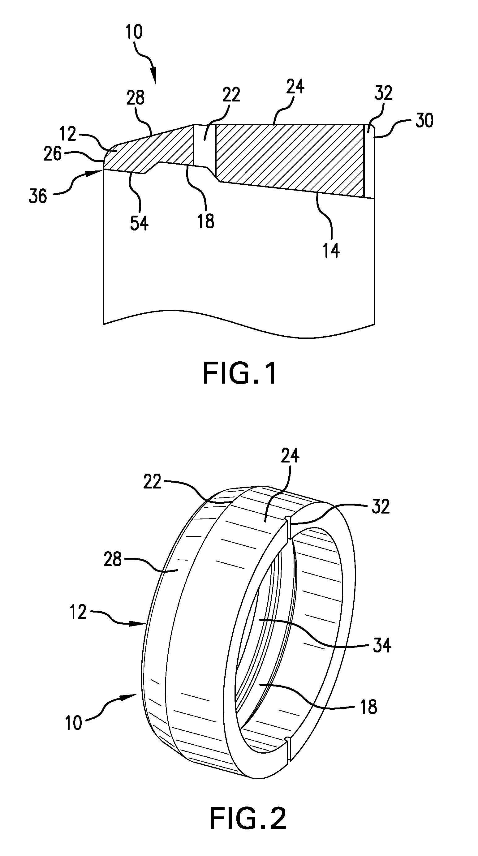
[0004] FIG. 1 is a cross sectional view of a seal element as disclosed herein;
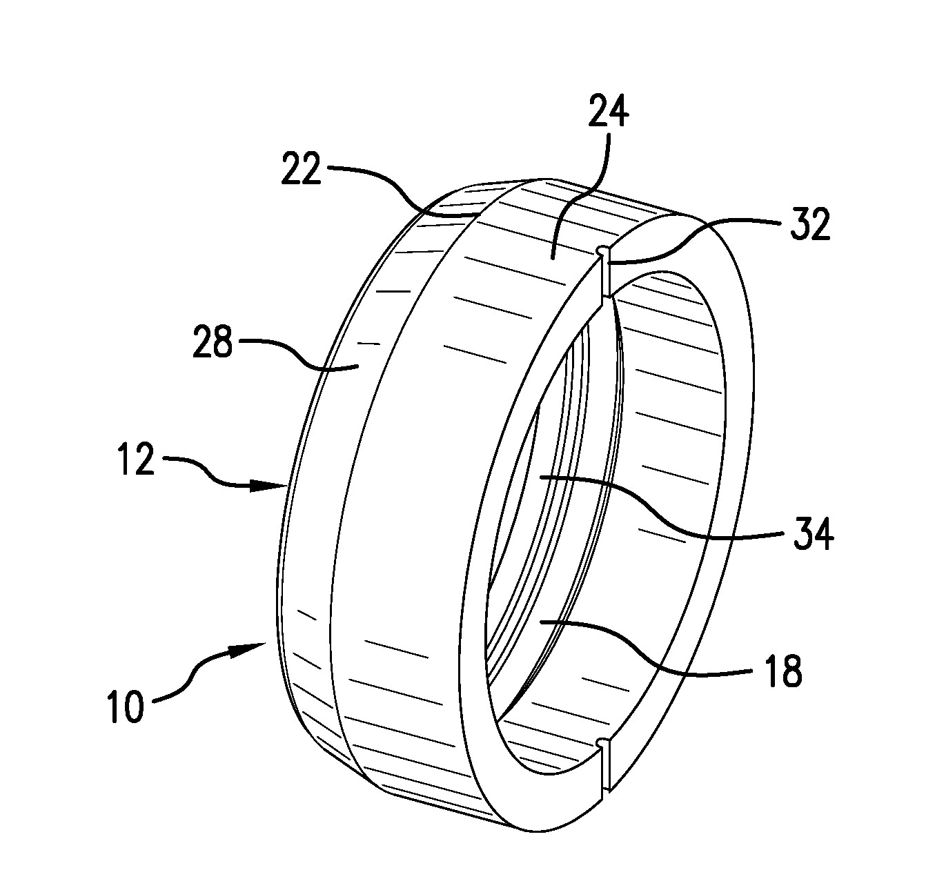
[0005] FIG. 2 is a perspective view of the seal element of FIG. 1; and
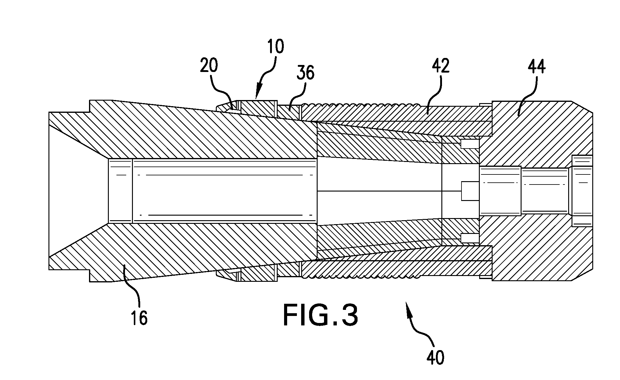
[0006] FIG. 3 is a cross sectional view of a fracture plug employing the seal element of FIG. 1.
DETAILED DESCRIPTION
[0007] A detailed description of one or more embodiments of the disclosed apparatus and method are presented herein by way of exemplification and not limitation with reference to the Figures.
[0008] Referring to FIG. 1 a seal element 10 as disclosed herein is of a swab resistant construction. The element 10 includes a lip 12. In the illustrated embodiment, the element 10 has a frustoconical inside surface 14 configured to cooperate with a frustoconical member 16 (see FIG. 3). Noticeable at the inside surface 14 is an undercut 18 that will leave an annular space 20 defined by the element 10 and the frustocone 16 when installed. The undercut 18 is intersected by a number of pathways 22 extending from undercut 18 to an outside surface 24 of element 10. When installed on a frustocone 16, the pathways 22 provide a fluid pathway from the outside surface 24 to the annular space 20, which is important to swab resistance discussed hereunder. Between a leading edge 26 of the lip 12 and the number of pathways 22, which if multiple, are arranged in an annular pattern about the element 10, is a ramp 28 of element 10. Between the number of pathways 22 and a trailing edge 30 of element 10, surface 24 is cylindrical in an embodiment. Finally a fluid path 32 is defined at the trailing edge 30 (in, on or around), which fluid path 32 may be radial or otherwise providing it provides a fluid pathway between a volume in contact with surface 24 and a volume under an adjacent backup ring 36 (See FIG. 3), which helps reduce or prevent damage to the backup ring 36. Finally, a lip undersurface 34 is in some embodiments dimensioned to provide a tight fit with a frustocone 16 with which it will used. By "tight fit" it is meant an interference fit to reduce or eliminate a fluid pathway between the element 10 and the frustocone 16. Element 10 may be constructed of material having 5% or more elongation. Some examples of suitable materials include but are not limited to rubber, plastic, elastomers, polymers, soft metals, etc.
[0009] The undercut 18 may be fully annular or may be part annular or may be in short portions that together define an annular form...like a dashed line wherein the dashes are undercuts. In each case, if the undercut is intended to provide for low pressure communication from the outside of the element to the annular space 20 (or part annular or dashed annular) then for each portion of the undercut that is to be so provided, a pathway 22 must extend to that undercut. Low pressure will not be communicated to the undercut without a pathway to the fluid flow area outside of the element 10.
[0010] The features of element 10 work together to dramatically improve swab off resistance to flow rates past the seal of 15 BBls per minute or even higher. The lip 12 ensures a low differential pressure at a nose 36 of element 10 as fluid flows therepast. At the same time, the undersurface 34 prevents high pressure fluid from reaching undercut 18 and surface 14 of element 10. In addition, pathways 22 allow low pressure found in a fluid passing over surfaces 22 and 24 (which obviously is in an annulus between the tool and a tubular within which the tool is being run) to be communicated automatically to the annular space 20, which tends to suck the element onto the frustocone 16 rather than allow it to be swabbed off due to the low pressure pulling the element 10 away from the frustocone 16.
[0011] 11 Referring to FIG. 3, a fracture plug 40 is illustrated that employs the element 10. The element 10 and backup 36 are disposed on the frustocone 16. The backup 36 is abutted by a slip 42, which in turn is abutted by a pusher 44. It will be understood that the seal element 10, backup 36 and slip 42 are pushed from a relatively narrower end of the frustocone 16 to a relatively larger end of frustocone 16 by displacement of the pusher 44 and the frustocone 16 relatively toward each other. It is to be understood that while a fracture plug has been used as an example of the use of the seal element 10 disclosed herein, the application of the element 10 is broader. It is to be recognized that the element 10 is also suitable for use in any other downhole tool that requires sealing or fluid flow inhibition and due to the design is applicable to tools that are subject to high flow rates of fluids therepast in the downhole environment. This includes for example liner hangers where the liner top packer is subject to high fluid flow rates therepast.
[0012] Set forth below are some embodiments of the foregoing disclosure:
[0013] Embodiment 1: An element including an undercut in the element extending from an innermost surface of the element radially outwardly into the element, and a pathway intersecting the undercut and extending from the undercut to an outermost surface of the element, the pathway fluidly connecting the outermost surface of the element to the undercut prior to setting of the seal.
[0014] Embodiment 2: The element as in any prior embodiment, further comprising a lip that is dimensioned to be 0.1% to 70% of the radial thickness of a remainder of the element.
[0015] Embodiment 3: The element as in any prior embodiment, wherein the lip includes an undersurface that creates a fluid tight fit with a separate component.
[0016] Embodiment 4: The element as in any prior embodiment, further comprising a ramp extending from the lip to an outside surface of the element, the undercut being at least partially located radially inwardly of the ramp.
[0017] Embodiment 5: The element as in any prior embodiment, wherein the undercut is fully annular.
[0018] Embodiment 6: The element as in any prior embodiment, wherein the undercut is part annular.
[0019] Embodiment 7: The element as in any prior embodiment, wherein the pathway is a plurality of pathways.
[0020] Embodiment 8: The element as in any prior embodiment, further including a fluid path at a trailing end of the element.
[0021] The use of the terms "a" and "an" and "the" and similar referents in the context of describing the invention (especially in the context of the following claims) are to be construed to cover both the singular and the plural, unless otherwise indicated herein or clearly contradicted by context. Further, it should be noted that the terms "first," "second," and the like herein do not denote any order, quantity, or importance, but rather are used to distinguish one element from another. The modifier "about" used in connection with a quantity is inclusive of the stated value and has the meaning dictated by the context (e.g., it includes the degree of error associated with measurement of the particular quantity).
[0022] The teachings of the present disclosure may be used in a variety of well operations. These operations may involve using one or more treatment agents to treat a formation, the fluids resident in a formation, a wellbore, and/or equipment in the wellbore, such as production tubing. The treatment agents may be in the form of liquids, gases, solids, semi-solids, and mixtures thereof. Illustrative treatment agents include, but are not limited to, fracturing fluids, acids, steam, water, brine, anti-corrosion agents, cement, permeability modifiers, drilling muds, emulsifiers, demulsifiers, tracers, flow improvers etc. Illustrative well operations include, but are not limited to, hydraulic fracturing, stimulation, tracer injection, cleaning, acidizing, steam injection, water flooding, cementing, etc.
[0023] While the invention has been described with reference to an exemplary embodiment or embodiments, it will be understood by those skilled in the art that various changes may be made and equivalents may be substituted for elements thereof without departing from the scope of the invention. In addition, many modifications may be made to adapt a particular situation or material to the teachings of the invention without departing from the essential scope thereof. Therefore, it is intended that the invention not be limited to the particular embodiment disclosed as the best mode contemplated for carrying out this invention, but that the invention will include all embodiments falling within the scope of the claims. Also, in the drawings and the description, there have been disclosed exemplary embodiments of the invention and, although specific terms may have been employed, they are unless otherwise stated used in a generic and descriptive sense only and not for purposes of limitation, the scope of the invention therefore not being so limited.
* * * * *
D00000
D00001
D00002
XML
uspto.report is an independent third-party trademark research tool that is not affiliated, endorsed, or sponsored by the United States Patent and Trademark Office (USPTO) or any other governmental organization. The information provided by uspto.report is based on publicly available data at the time of writing and is intended for informational purposes only.
While we strive to provide accurate and up-to-date information, we do not guarantee the accuracy, completeness, reliability, or suitability of the information displayed on this site. The use of this site is at your own risk. Any reliance you place on such information is therefore strictly at your own risk.
All official trademark data, including owner information, should be verified by visiting the official USPTO website at www.uspto.gov. This site is not intended to replace professional legal advice and should not be used as a substitute for consulting with a legal professional who is knowledgeable about trademark law.