Building Foundation Repair Product
BARTON; DONALD
U.S. patent application number 16/383102 was filed with the patent office on 2019-10-17 for building foundation repair product. The applicant listed for this patent is DONALD BARTON. Invention is credited to DONALD BARTON.
| Application Number | 20190316314 16/383102 |
| Document ID | / |
| Family ID | 68161394 |
| Filed Date | 2019-10-17 |


| United States Patent Application | 20190316314 |
| Kind Code | A1 |
| BARTON; DONALD | October 17, 2019 |
BUILDING FOUNDATION REPAIR PRODUCT
Abstract
The present example provides a building foundation repair product that is a horizontally cast concrete product. Horizontal casting, unlike the typical vertical casting produces smooth end surfaces that aid in installing the building foundation repair product as the end surfaces are defined by the mold. Also, the building foundation repair product has been designed with flat surfaces that make up its sides. The flat surfaces advantageously tend to prevent the product from rolling when used at a job site, and allows the a building foundation repair product to be easily palletized for shipping, as they tend to be stable when stacked on the pallet.
| Inventors: | BARTON; DONALD; (Houston, TX) | ||||||||||
| Applicant: |
|
||||||||||
|---|---|---|---|---|---|---|---|---|---|---|---|
| Family ID: | 68161394 | ||||||||||
| Appl. No.: | 16/383102 | ||||||||||
| Filed: | April 12, 2019 |
Related U.S. Patent Documents
| Application Number | Filing Date | Patent Number | ||
|---|---|---|---|---|
| 62657726 | Apr 14, 2018 | |||
| Current U.S. Class: | 1/1 |
| Current CPC Class: | E02D 5/30 20130101; E02D 5/665 20130101; E02D 37/00 20130101 |
| International Class: | E02D 37/00 20060101 E02D037/00; E02D 5/66 20060101 E02D005/66; E02D 5/30 20060101 E02D005/30 |
Claims
1. A building foundation repair product formed by a process comprising: filling a horizontally oriented mold for forming a right irregular cylinder with rounded square bases with concrete, from a side; striking off excess cement from the mold; compacting the cement; forming a radius; and replacing a radius forming rod with a division plate.
2. The building foundation repair product formed by a process of claim 1, in which compacting is provided by vibrating.
3. The building foundation repair product formed by a process of claim 1, further comprising forming rod apertures in the foundation repair product.
4. The building foundation repair product formed by a process of claim 1, further comprising curing the foundation repair product.
5. The building foundation repair product formed by a process of claim 1, further comprising lifting the mold into position.
6. A building foundation repair product comprising: a concrete block shaped in the form of a right irregular cylinder with rounded square bases.
7. The building foundation repair product of claim 6 in which a length from a top rounded square base to a bottom rounded square base is twelve inches.
8. The building foundation repair product of claim 6 in which a distance between parallel flat surfaces is five and a half inches.
9. The building foundation repair product of claim 6 in which each corner of a plurality of rounded corners has a one and a half inch radius.
10. The building foundation repair product of claim 6 further comprising a longitudinal circular cylindrical aperture centered in the top and bottom rounded square bases.
11. The building foundation repair product of claim 6 in which the rounded square bases include a top rounded square base and a bottom rounded square base each formed by concrete in contact with a mold surface.
Description
CROSS-REFERENCE TO RELATED APPLICATION
[0001] This application claims the benefit of U.S. Provisional Patent Application No. 62/657,726 filed Apr. 14, 2018, the contents of which are hereby incorporated by reference.
TECHNICAL FIELD
[0002] This description relates generally to masonry building products and more specifically to building foundation repair.
BACKGROUND
[0003] Buildings are prone to settling as they age and the underlying soil compacts or otherwise changes over time. Settling can cause cracks in walls and floors, as well a degradation of a level surface. In colder climates buildings tend to have more substantial footings due to the freezing and thawing that necessitates a deeper footing to extend below the frost line. In warmer areas not prone top freezing the building may merely be constructed on a concrete slab poured in place. Both types of foundation are prone to settling. In slab construction a remedy for a sinking or cracked foundation may be to excavate under the slab and attempt to raise it back to its original level by various methods. Accordingly a building foundation repair product would be useful in supporting damaged building foundations and slabs would be desirable.
SUMMARY
[0004] The following presents a simplified summary of the disclosure in order to provide a basic understanding to the reader. This summary is not an extensive overview of the disclosure and it does not identify key/critical elements of the invention or delineate the scope of the invention. Its sole purpose is to present some concepts disclosed herein in a simplified form as a prelude to the more detailed description that is presented later.
[0005] The present example provides a building foundation repair product that is a horizontally cast concrete product. Horizontal casting, unlike the typical vertical casting produces smooth end surfaces that aid in installing the building foundation repair product as the end surfaces are defined by the mold. Also, the building foundation repair product has been designed with flat surfaces that make up its sides. The flat surfaces advantageously tend to prevent the product from rolling when used at a job site, and allows the a building foundation repair product to be easily palletized for shipping, as they tend to be stable when stacked on the pallet.
[0006] Many of the attendant features will be more readily appreciated as the same becomes better understood by reference to the following detailed description considered in connection with the accompanying drawings.
DESCRIPTION OF THE DRAWINGS
[0007] The present description will be better understood from the following detailed description read in light of the accompanying drawings, wherein:
[0008] FIG. 1 shows a method of installing piers to repair a cracked foundation.
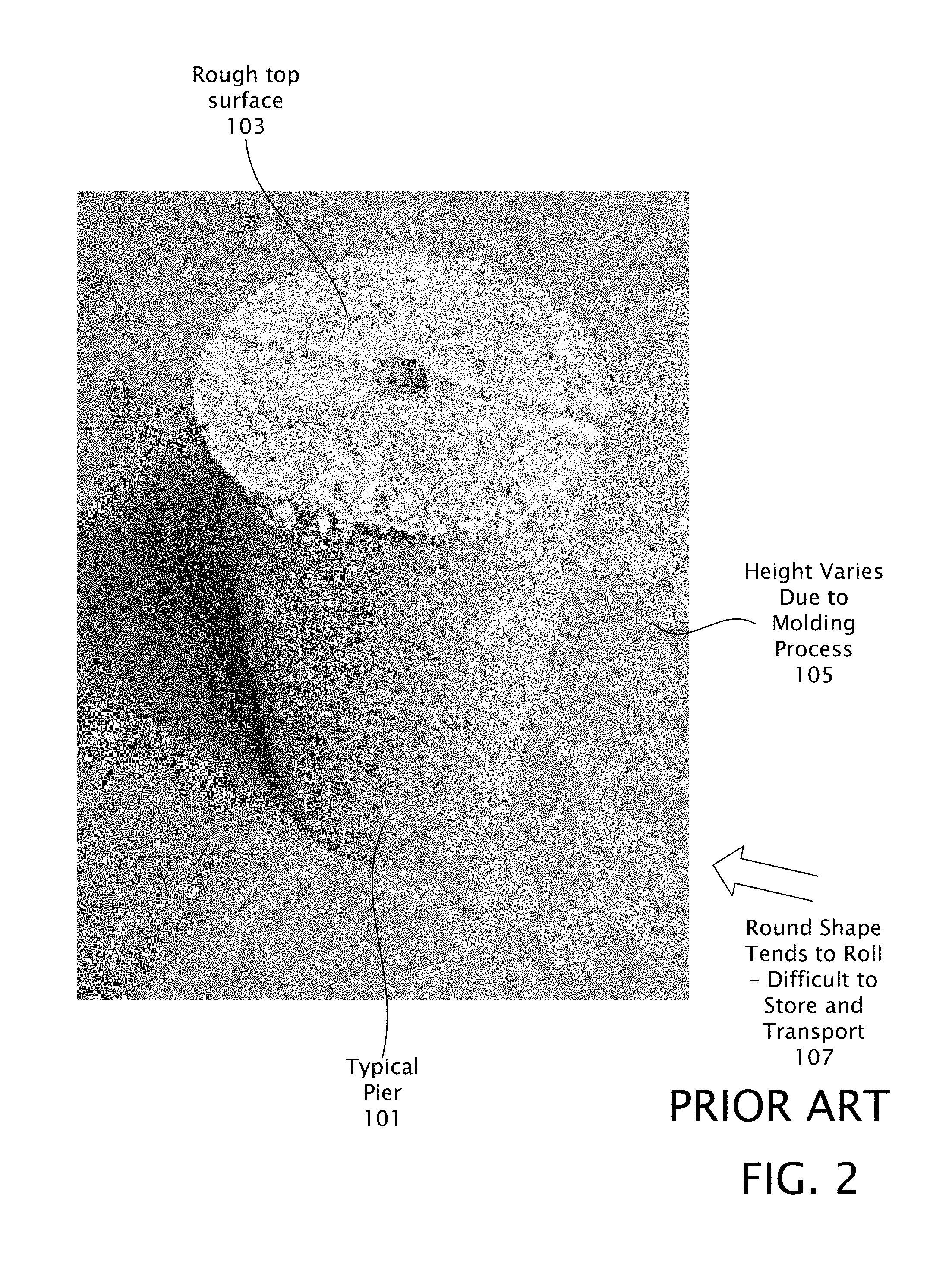
[0009] FIG. 2 shows a typical pier used in foundation repair.
[0010] FIG. 3 shows an improved building foundation repair product.
[0011] FIG. 4 shows an inclined view of the improved building foundation repair product.
[0012] FIG. 5 shows a plan view of the improved building foundation repair product.
[0013] FIG. 6 shows a pallet of improved building foundation repair products prepared for shipping.
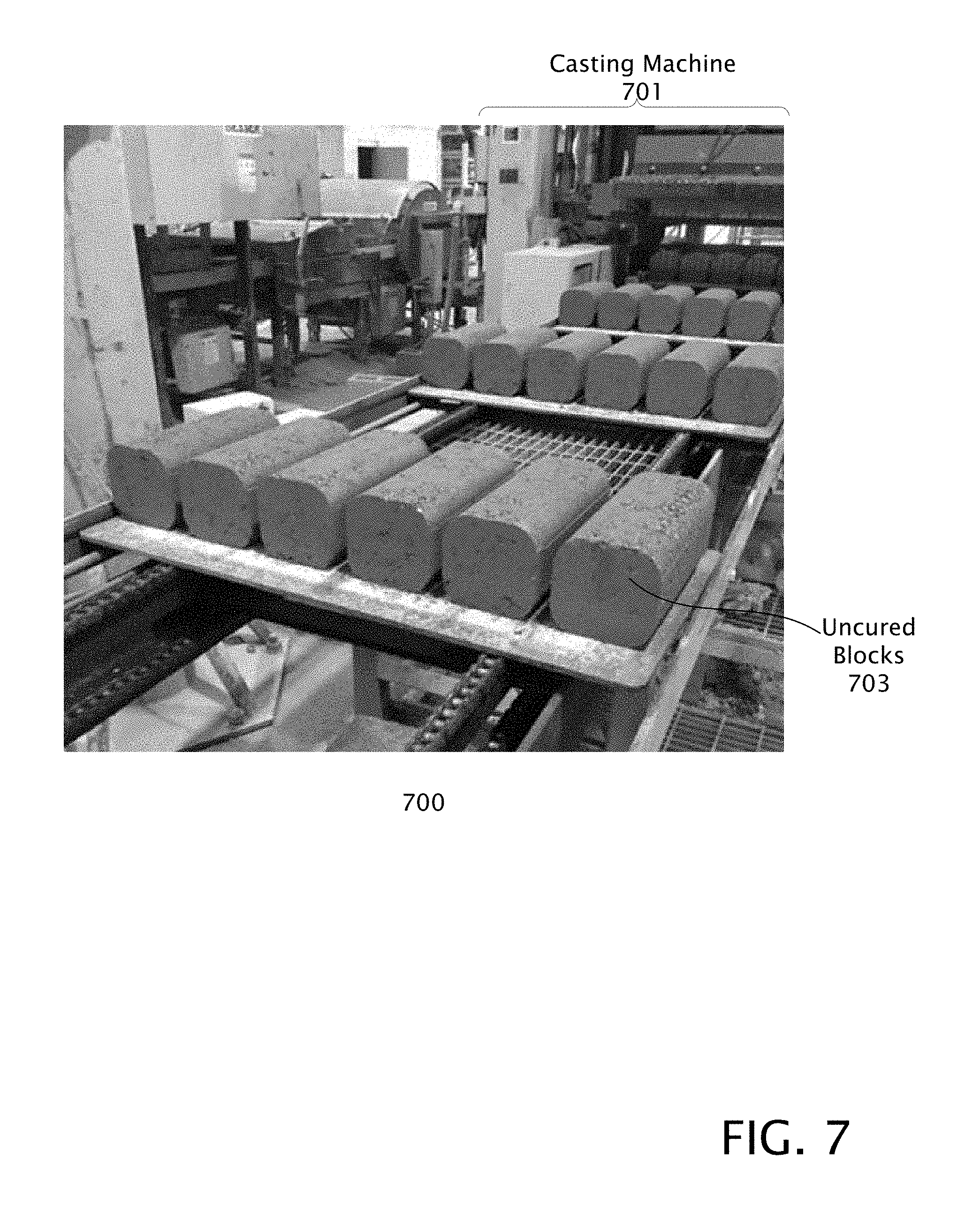
[0014] FIG. 7 shows uncured horizontally cast improved building foundation repair products exiting the casting machine.
[0015] FIG. 8 shows details of the mold mechanism for casting improved building foundation repair products.
[0016] FIG. 9 shows the mold for casting improved building foundation repair products.
[0017] FIG. 10 is a flow diagram showing a process for manufacturing the improved building foundation repair product.
[0018] Like reference numerals are used to designate like parts in the accompanying drawings.
DETAILED DESCRIPTION
[0019] The detailed description provided below in connection with the appended drawings is intended as a description of the present examples and is not intended to represent the only forms in which the present example may be constructed or utilized. The description sets forth the functions of the example and the sequence of steps for constructing and operating the example. However, the same or equivalent functions and sequences may be accomplished by different examples.
[0020] The examples below describe a building foundation repair product (or equivalently a "block" or "pier"). Although the present examples are described and illustrated herein as being implemented in a house foundation repair system, the system described is provided as an example and not a limitation. As those skilled in the art will appreciate, the present examples are suitable for application in a variety of different types of foundation leveling systems.
[0021] As utilized herein a rounded square shape, may be generated by separating four quarters of a circle and connecting their loose ends with straight lines, or by separating the four sides of a square and connecting them with quarter-circles. The rounded square can be scaled up or down quite easily. Another way to describe a rounded square is as a square simply having rounded corners.
[0022] As utilized herein generally a prism is a shape having flat sides connecting two parallel bases. The bases are polygons (either regular or irregular). If the bases are not parallel, then the shape is not a prism. Each side of a prism is a parallelogram. A prism with square bases is a square prism.
[0023] In addition to the attributes of a prism, and as utilized herein a square prism is a three dimensional solid object whose bases are squares. In a square prism, the opposite sides and angles are congruent. A cube is a special case of a square prism as the lines connecting the faces are the same length as the lines making up the square bases.
[0024] As utilized herein a cylinder shape has one curved side coupling two parallel bases. The bases are curved shapes (either regular or irregular). If the bases are not parallel, then the shape is not a cylinder. A cylinder with round bases is a circular cylinder.
[0025] Prisms and cylinders may be right (the bases are perpendicular to the sides), or oblique (the bases are not perpendicular to the sides). Bases may be regular or irregular. A regular shape is one having equal edge lengths, and/or equal angles. Both prisms and cylinders have bases that are coupled together by the sides. Both prisms and cylinders have cross sections that are identical to the bases. A cylinder has one side, and a prism may have an infinite number of sides.
[0026] The term cement as used herein is a binding material, typically used in construction that sets, hardens, and adheres to other materials, thus binding them together. Cement is seldom used without adding other substances that it binds together. Typically cement binds sand and gravel (aggregate) in various forms together. Cement mixed with fine aggregate is termed mortar that may be used in setting masonry bricks. When cement is mixed with sand and gravel concrete that may be formed or cast in various shapes is produced. Mortar and concrete are typically mixed with water when being prepared for use. Cement may be of the non-hydraulic, or hydraulic type (Portland cement). Portland cement, that is widely used, typically contains calcium carbonate (lime) that has been heated to form calcium oxide (quicklime) and other additives such as gypsum. Cement may also be mixed with other substances such as pigment and the like.
[0027] FIG. 1 shows a system for installing piers 207, 209 to repair a cracked 203 foundation 201. Building foundations 201, especially slab type construction, are typically subject to settling and shifting over time. This can lead to cracks 203 in walls, slabs, and other damage to a building. A typical technique for repairing this type of damage to a slab foundation is to excavate 205 around a foundation 201 perimeter at periodic intervals, with the excavation 205 extending under the foundation 201 so that one or more support piers 207, 209 may be driven into the ground to support the foundation 201. A concrete cylinder 209 (conventional building foundation repair product) is typically placed under the foundation (here shown installed on top of a previously installed pier 207). A hydraulic jack or equivalent 211 may be inserted in the gap 214 between the bottom surface of the foundation and the top of the concrete cylinder or pier 207.
[0028] When the jack 211 is pumped, expanding it, the cylinder 207, 209 is typically driven into the earth (or as shown here further driving the second pier 207 further into the ground). The process is repeated adding additional cylinders until they can no longer be driven into the earth, and a stable support for the foundation has been created. At this point the foundation is leveled and a final remaining gap between the foundation and cylinder 213 is filled with shims (typically stainless steel or the like-not shown). The excavation 205 is filled in and the foundation 201 is now level so that the structure may now be repaired.
[0029] It is worth pointing out that the piers, 207, 209 as typically used are cylindrical. As far as is known this is a carry over from when round wooden pilings or posts driven into the earth such as this in order to support a structure such as a building, dock, or the like. There is apparently no particular reason for the round shape, other than historical tradition, as the round shape can create some, until this time unsolved, problems for this leveling methos.
[0030] FIG. 2 shows a typical pier, or equivalently pile 101 used in foundation repair. Some of the drawbacks to these piers 101 include, the round shape 107 being difficult to handle and package (they roll) 107, the finish surface 103 on the top/bottoms is uneven and coarse (which can lead to failure), and the varying heights of the units inherent in their manufacturing process.
[0031] Manufacturers of round cylinder foundation repair piers 101 typically invariably cast them vertically in the shape of a generally circular cylinder, in cylindrical forms, as this is typically the easiest way to cast a cylinder. Vertical casting often results in rough concrete debris remaining on the side forming the top base of the piers 101. The end user typically must clean each unit with a hammer and chisel to insure no protrusions, that could lead to failure, during the hydraulic push into the ground at up to 10,000 psi. The pressure points tend to concentrate the force which can crack the pier. Vertical casting has been done for many years in spite of the difficulties encountered by foundation repairmen with obtaining a smooth top and bottom surface that can take the pressure produced by a jack driving the pier into the ground.
[0032] The length of the piers 105 tends to vary during the forming process. Screeding off the top surface after the mold has been filled does not lend itself to constant height pier as the screed may not be pressed level with the top of the form, either by insufficient application of pressure, or by aggregate protruding above the form and being resistant to the screed pushing it down into the form, which also leads to the above mentioned rough surfaces 103.
[0033] Typical round piles 101 are difficult to package and transport. The round shape of cylinders is difficult to handle from the point of manufacture to the final installation, as they tend to roll due to the round shape. In packing they may be set upright on their bases, but if care is not always taken to set them, on end, on level ground they can easily roll. In spite of the above mentioned difficulties piers have been made as described above until this time to repair cracked or uneven foundations.
[0034] By realizing the drawbacks above, this discovery of the problem is the invention that has led to the development of an improved building foundation repair product. Cylindrical piers 101 have been used throughout the industry for years without improvement. In fact, other methods of foundation leveling that have been developed have taught away from improvement of the piers, as such things as helical piers, steel piers and the like have been use as alternatives to the cylindrical concrete piers. However, improved concrete piers are apparently not be available.
[0035] FIG. 3 shows an improved building foundation repair product 300. Since introduction of this product demand, and hence sales have been strong, showing that the improved building foundation repair product has satisfied a long felt unmet need in the foundation repair industry. The improved building foundation repair product is designed to solve the issues discussed above regarding conventional piers while retaining the performance specifications of piers typically used in foundation leveling. A manufacturing method to make the improved building foundation repair product has also been developed that enables the improvements in the improved building foundation repair product. In short a horizontal molding process applied to making the improved building foundation repair product allows the above mentioned problems with respect to conventional cylindrical piers to be solved.
[0036] Benefits of the new design provides flat top and bottom bases 303 for ease of installation, not requiring extra steps to clean, brush and chip debris. The flat top 304 and bottom 302 bases significantly reduces potential of failure due to raised debris. The height between the top and bottom bases is also uniform and controlled by the mold. Height of unit is consistent 12'', or as desired for a given application 309.
[0037] The improved building foundation repair product may be stacked on its sides or ends without rolling. Units have flat sides 307 to prevent rolling. In fact any conceivable surface upon which the improved building foundation repair product comes to rest upon will not lead to rolling. The improved building foundation repair product allows for safe packaging when palletized for shipment.
[0038] In alternative examples of the improved building foundation repair product other shapes that prevent rolling may be produced that are also cast horizontally and have smooth ends. For example polygons such as rectangular, semicircular, hexagonal, or other polygons will provide flat sides from a horizontal mold that tends to prevent rolling.
[0039] The rounded corners 301 tend to prevent chipping and strengthen the improved building foundation repair product. It is also contemplated that in equivalent examples the rounded corners 301 along the long axis of the building foundation repair product as described herein, may equivalently be replaced by a simple beveled edge or the like. In general reducing edges along the long axis of the building foundation repair product ("knocked down edges"), make it less prone to damage, chipping, or the like. In general round or generally curved edges tend to be utilized in the building foundation repair product. The improved building foundation repair product 300 may also include a longitudinal aperture 305 formed therein, to accommodate an alignment rod (not shown) which may be used during foundation repair.
[0040] FIG. 4 shows an inclined view of the improved building foundation repair product 300. The improved building foundation repair product 300 may be describes as having the shape of a right (not oblique) irregular cylinder, with bases in the shape of a rounded square 401. Top base 304 and bottom base area 302 are in the shape of a rounded square and identical. An aperture 405 may be disposed along a longitudinal axis of the improved building foundation repair product. Typically the aperture 405 has the outline of a circular cylinder.
[0041] As a cylinder type of shape there is one side that wraps around the top 304 and bottom 302 bases. The one side includes four flat surfaces areas (two of which are shown 307, 308), each longitudinally adjoining a rounded corner area in four places. The four rounded corner areas are identical. The four surface areas are each rectangular and identical.
[0042] FIG. 5 shows a plan view of the improved building foundation repair product 300. The plan view of the rounded square bottom base 302 is identical to the plan view of the rounded square top base 405 shown, and is left out for simplification. The plan view of the left side 509, the right side 507, and the bottom side 505 are identical to the plan view of the top side 520 (shown) and are omitted for the sake of brevity.
[0043] The dimensions of the rounded square base area 304 of the improved building foundation repair product 300 are 5.5 inches between sides. Those skilled in the art will realize that this dimension is exemplary and other equivalent dimensions may be utilized. The flat side areas 307 of the rounded square base 501 are coupled by an exemplary 1.5 inch radius quarter circle shaped surfaces.
[0044] Those skilled in the art will realize that the improved building foundation repair product 300 may be cast in equivalent examples having top and bottom bases that will also provide a flat side to stop rolling. For example rectangular, hexaganol, octogonal, compound shapes, shape that provide one or more flat surfaces, or the like.
[0045] The height of the improved building foundation repair product 300 is 12 inches. The dimensions provided are exemplary only and not intended to be limiting.
[0046] The improved building foundation repair product 300 can be produced with or without a center aperture 405 (which may be provided to accommodate a reinforcement rod added during instillation), typically 3/4'' in diameter. The use of a center aperture 405 is a preference by some installers with no additional or loss of strength. The defining characteristic of the unit is the smooth top and bottom which can only be achieved by the new manufacturing design using a mold having a top and bottom base in fixed relation to each other.
[0047] FIG. 6 shows a pallet of a plurality of improved building foundation repair products 300 prepared for shipping 600. The improved building foundation repair products 300 stack neatly on a typical pallet 601, to which they may be securely strapped.
[0048] FIG. 7 shows production 700 of uncured horizontally cast improved building foundation repair products 703 exiting the casting machine 701. Horizontal casting in a mold that has top and bottom surfaces as part of the mold enable the previously described attributes to be obtained. A casting machine 701 such as the exemplary Besser Ultrapac Concrete Products Machine may be used with a custom made mold to produce improved building foundation repair products at an exemplary rate of 36 improved building foundation repair products per minute. Besser Ultrapac Concrete Products Machiene is manufactured by Besser Inc. located at 801 Johnson Street, Alpena Mich.
[0049] A wide variety of sizes and types of machines may be utilized to mold the improved building foundation repair products. For example the improved building foundation repair products could be molded one at a time by hand if desired. However, automated equipment such as the exemplary casting machine tends to efficiently and consistently produce the improved building foundation repair products.
[0050] The concrete is transferred to the casting machine where it is fed into the mold which has been previously set up in the machine. The configuration of the mold in general determines the size and style of the products produced, as the casting machine tends to be general purpose in nature. Interchangable molds allows the manufacturer to make a wide range of concrete products using the same equipment in the same facility. Depending upon the demand for products the mold may be changed after several hours, days or weeks.
[0051] Once placed into the mold the concrete is typically compacted and consolidated by a combination of pressure and controlled vibration. Vibration may be customized for each improved building foundation repair product being produced ensuring high quality products with maximum compaction, uniformity and strength. At the end of the molding cycle the improved building foundation repair products are expelled from the mold onto a pallet or board depending upon the factory set up.
[0052] As the products leave the casting machine a rotating brush or a short blast of air can be used to remove loose pieces of concrete. At this point the products are referred to as "green", and then cured in a conventional manner prior to shipping.
[0053] FIG. 8 shows a simplified top view 800 the mold mechanism for casting improved building foundation repair products. The mold is designed with sliding split division plates 814 that move forward and back to create the radius detail on the bottom side of the improved building foundation repair product as a number of them are being manufactured. This manufacturing design is unique to this mold. Molding the product horizontally allows for both ends of the unit to be flat-as fixed by the mold dimensions. Concrete is added from the side (rather than the top) and a compacting head acts to smooth the side where the concrete fills the mold. Horizontal casting improves performance of the improved building foundation repair product and eliminates the need for field clean up of the ends. Subsequent field testing of the product has provided very positive feedback. ASTM strength testing of the building foundation repair product has also been encouraging.
[0054] The core rods 812 form the apertures in the improved building foundation repair product.
[0055] The block produced by horizontal molding has ends that contact the mold and produce smooth ends, as opposed to a vertical casting process that leaves the ends rough.
[0056] FIG. 9 shows the mold 900 for horizontally casting improved building foundation repair products. This mold allows six improved building foundation repair products to be produced at a time. The number produced is exemplary, and molds for producing different numbers of improved building foundation repair products may equivalently created. However all molds have surfaces that define the top and bottom bases of the improved building foundation repair products that are in fixed relation to each other, so that smooth ends may be produced.
[0057] FIG. 10 is a flow diagram showing a process for manufacturing the improved building foundation repair product 1000. At building foundation repair product 1002 the mold is lifted in position. The mold is filled with cement having an optional smoothing agent added at 1004. The excess material is struck off at 1006 A head compacts the material in the mold 1008. The radius is pulled out, and replaced with a division plate 1009 At block 1010 apertures through the block are formed with a rod. And finally the building foundation repair product is cured.
[0058] Those skilled in the art will realize that the process sequences described above may be equivalently performed in any order to achieve a desired result. Also, sub-processes may typically be omitted as desired without taking away from the overall functionality of the processes described above.
* * * * *
D00000
D00001
D00002
D00003
D00004
D00005
D00006
D00007
D00008
D00009
D00010
XML
uspto.report is an independent third-party trademark research tool that is not affiliated, endorsed, or sponsored by the United States Patent and Trademark Office (USPTO) or any other governmental organization. The information provided by uspto.report is based on publicly available data at the time of writing and is intended for informational purposes only.
While we strive to provide accurate and up-to-date information, we do not guarantee the accuracy, completeness, reliability, or suitability of the information displayed on this site. The use of this site is at your own risk. Any reliance you place on such information is therefore strictly at your own risk.
All official trademark data, including owner information, should be verified by visiting the official USPTO website at www.uspto.gov. This site is not intended to replace professional legal advice and should not be used as a substitute for consulting with a legal professional who is knowledgeable about trademark law.