Process For Producing Low-carbon Olefins By Gaseous Phase Catalytic Cracking Of Heavy Oil With Multi-stages In Milliseconds
Tian; Yuanyu ; et al.
U.S. patent application number 16/386914 was filed with the patent office on 2019-10-17 for process for producing low-carbon olefins by gaseous phase catalytic cracking of heavy oil with multi-stages in milliseconds. This patent application is currently assigned to China University of Petroleum (East China). The applicant listed for this patent is China University of Petroleum (East China). Invention is credited to Yuanjun Che, Wen Feng, Yuan Jiang, Xinmei Liu, Yingyun Qiao, Yuanyu Tian, Jinhong Zhang.
| Application Number | 20190316041 16/386914 |
| Document ID | / |
| Family ID | 63382173 |
| Filed Date | 2019-10-17 |

| United States Patent Application | 20190316041 |
| Kind Code | A1 |
| Tian; Yuanyu ; et al. | October 17, 2019 |
PROCESS FOR PRODUCING LOW-CARBON OLEFINS BY GASEOUS PHASE CATALYTIC CRACKING OF HEAVY OIL WITH MULTI-STAGES IN MILLISECONDS
Abstract
The invention provides a process for producing low-carbon olefins by gaseous phase catalytic cracking of heavy oil with multi-stages in milliseconds, comprising: a high-efficiency atomizing nozzle sprays the preheated heavy oil into an upper portion of the downflow modification reaction tube, the produced oil mist is mixed with a high temperature heat carrier flowing downward from a return controller for pyrolysis, and then the pyrolysis products are subject to a gas-solid separation at the bottom of the downflow modification reaction tube; then the coked heat carrier obtained by the separation enters into a lower portion of a modification regeneration reactor to conduct a regeneration reaction, the obtained regeneration gas and the high temperature heat carrier are subject to a gas-solid separation on the top of the modified regeneration reactor, then the high temperature heat carrier returns to a top of the downflow reaction tube to participate in circulation, the regeneration gas is subject to heat exchange and then output; and the high temperature oil and gas produced by the pyrolysis reaction directly flows into the millisecond cracking reactor and conducts a cracking reaction with the regenerated cracking catalyst and subject to a gas-solid separation; then the cracking catalyst to be regenerated enters a lower portion of the crack regeneration reactor and performs a regeneration reaction, the obtained flue gas and the high temperature crack catalyst are subject to a gas-solid separation at the top of the crack regeneration reactor, the high temperature crack catalyst returns to the millisecond cracking reactor to participate the circulation reaction, the flue gas is subject to heat exchange and then output; the crack oil and gas produced by the cracking reaction enter into the subsequent separation devices to separate out the low carbon olefins.
| Inventors: | Tian; Yuanyu; (Qingdao, CN) ; Qiao; Yingyun; (Qingdao, CN) ; Zhang; Jinhong; (Qingdao, CN) ; Liu; Xinmei; (Qingdao, CN) ; Che; Yuanjun; (Qingdao, CN) ; Jiang; Yuan; (Qingdao, CN) ; Feng; Wen; (Qingdao, CN) | ||||||||||
| Applicant: |
|
||||||||||
|---|---|---|---|---|---|---|---|---|---|---|---|
| Assignee: | China University of Petroleum (East
China) Qingdao CN |
||||||||||
| Family ID: | 63382173 | ||||||||||
| Appl. No.: | 16/386914 | ||||||||||
| Filed: | April 17, 2019 |
| Current U.S. Class: | 1/1 |
| Current CPC Class: | C10G 2300/1077 20130101; C10G 2300/4081 20130101; C10G 11/05 20130101; C10G 2300/1074 20130101; C10G 2300/4006 20130101; C10G 11/182 20130101; C10G 2400/30 20130101; C10G 7/00 20130101; C10G 2400/20 20130101 |
| International Class: | C10G 11/05 20060101 C10G011/05; C10G 7/00 20060101 C10G007/00; C10G 11/18 20060101 C10G011/18 |
Foreign Application Data
| Date | Code | Application Number |
|---|---|---|
| Apr 17, 2018 | CN | 201810341227.0 |
Claims
1. A process for producing low-carbon olefins by gaseous phase catalytic cracking of heavy oil with multi-stages in milliseconds, wherein: 1) a high-efficiency atomizing nozzle sprays the heavy oil preheated to 150.degree. C.-350.degree. C. from a feed inlet of a downflow modification reaction tube into an upper portion of the downflow modification reaction tube, the produced oil mist is mixed with a high temperature solid heat carrier at a temperature ranging from 650.degree. C.-1,200.degree. C. flowing downward from a first return controller for milliseconds, so as to heat, vaporize and pyrolyze the oil mist and obtain an oil and gas and a solid heat carrier to be regenerated, the pyrolysis reaction temperature is within a range of 480.degree. C.-850.degree. C.; 2) the oil and gas as well as the solid heat carrier to be regenerated flow rapidly and downward to a first rapid gas-solid separator at the bottom of the downflow modification reaction tube to carry out a gas-solid separation to obtain a coked solid heat carrier to be regenerated and a high temperature oil and gas; 3-1) the coked solid heat carrier to be regenerated flows through a first flow controller and enters into a lower portion of a modification regeneration reactor to conduct a regeneration reaction with a regeneration agent, the temperature of the regeneration reaction is within a range of 680.degree. C.-1,250.degree. C.; then the regeneration gas and high temperature solid heat carrier produced by the regeneration reaction are subject to a gas-solid separation in a first gas-solid separator on top of the modification regeneration reactor, then the high temperature solid heat carrier with a carrier/oil ratio of 1-14 passes through the first return controller and flows into a top of the downflow modification reaction tube and enter into the downflow modification reaction tube so as to participate in circulation and cracking of the heavy oil; the regeneration gas from the first gas-solid separator is subject to heat exchange and then output; 3-2) the high temperature oil and gas from the first rapid gas-solid separator is not condensed but directly flowing in the gaseous phase into a millisecond cracking reactor and mixing with a regeneration cracking catalyst having a temperature of 600.degree. C.-850.degree. C. to carry out a gas phase catalytic cracking reaction, the cracking reaction temperature is within a range of 530.degree. C.-750.degree. C., then a cracking oil and gas and a cracking catalyst to be regenerated produced by the cracking reaction are subject to gas-solid separation in milliseconds; 4-1) the cracking catalyst to be regenerated flows through a second flow controller and enters a lower portion of the crack regeneration reactor and performs a regeneration reaction with air, the temperature of the regeneration reaction is 630.degree. C.-900.degree. C., a flue gas and a high temperature crack catalyst produced by the regeneration reaction are subject to a gas-solid separation in a second gas-solid separator at the top of the crack regeneration reactor; the high temperature crack catalyst with a catalyst/oil ratio of 1-8 passes through a second return controller and flows into the millisecond cracking reactor to participate the circulation reaction, and the flue gas is subject to heat exchange and then output; 4-2) the cracking oil and gas produced by the cracking reaction enter into the subsequent separation devices to separate out the low carbon olefins and aromatic hydrocarbons.
2. The process for producing low-carbon olefins by gaseous phase catalytic cracking of heavy oil with multi-stages in milliseconds according to claim 1, wherein the heavy oil is one selected from a group consisting of vacuum residue oil, atmospheric pressure residue oil, distillate, crude oil, coal tar, shale oil and oil sand bitumen.
3. The process for producing low-carbon olefins by gaseous phase catalytic cracking of heavy oil with multi-stages in milliseconds according to claim 1, wherein the regenerant agent is an oxidizing agent or a mixture of an oxidizing agent and water vapor, wherein the oxidizing agent is one of oxygen, air and oxygen-enriched air; and the regeneration gas is syngas or flue gas.
4. The process for producing low-carbon olefins by gaseous phase catalytic cracking of heavy oil with multi-stages in milliseconds according to claim 1, wherein the solid heat carrier is one of semi-coke microspheres, calcium aluminate porous microspheres, magnesium aluminate spinel porous microspheres, aluminum silicate porous microspheres, calcium silicate porous microspheres, magnesium silicate porous microspheres, porous microsphere carriers loaded with alkali metals or/and alkaline-earth metals or a mixture thereof.
5. The process for producing low-carbon olefins by gaseous phase catalytic cracking of heavy oil with multi-stages in milliseconds according to claim 1, wherein the first gas-solid separator and the second gas-solid separator are one selected from the group consisting of an inertial separator, a horizontal cyclone separator, and a vertical cyclone, respectively.
6. The process for producing low-carbon olefins by gaseous phase catalytic cracking of heavy oil with multi-stages in milliseconds according to claim 1, wherein the cracking catalyst is one selected from a group consisting of a FCC molecular sieve catalyst, a shape selective molecular sieve catalyst and an alkaline solid porous catalyst or a mixture thereof.
7. The process for producing low-carbon olefins by gaseous phase catalytic cracking of heavy oil with multi-stages in milliseconds according to claim 1, wherein the modification regeneration reactor is one selected from a group consisting of a riser regenerator, a turbulent fluidized bed regenerator and a bubbling fluidized bed regenerator.
8. The process for producing low-carbon olefins by gaseous phase catalytic cracking of heavy oil with multi-stages in milliseconds according to claim 1, wherein the millisecond cracking reactor is one selected from a group consisting of a downflow tube reactor, a horizontal inertia rotary separation reactor and a cross-staggered short contact reactor.
9. The process for producing low-carbon olefins by gaseous phase catalytic cracking of heavy oil with multi-stages in milliseconds according to claim 1, wherein the first rapid gas-solid separator and the second rapid gas-solid separator are one selected from an inertial separator and a horizontal cyclone separator, respectively.
10. The process for producing low-carbon olefins by gaseous phase catalytic cracking of heavy oil with multi-stages in milliseconds according to claim 1, wherein the crack regeneration reactor is one selected from a group consisting of a riser regenerator, a turbulent fluidized bed regenerator and a bubbling fluidized bed regenerator.
Description
CROSS REFERENCE TO RELATED APPLICATIONS
[0001] The application claims priority to Chinese Application No. 201810341227.0, filed on Apr. 17, 2018, entitled "Process for Producing Low-carbon Olefins by Gaseous Phase Catalytic Cracking of Heavy Oil with Multi-stages in Milliseconds", which is specifically and entirely incorporated herein by reference.
FIELD OF THE INVENTION
[0002] The invention provides a process for producing low-carbon olefins by gaseous phase catalytic cracking of heavy oil with multi-stages in milliseconds, it belongs to the technical field of heavy oil processing.
BACKGROUND OF THE INVENTION
[0003] The low-carbon olefins such as ethylene, propylene, butene and butadiene are vital basic organic chemical materials, especially the production capability of ethylene is often regarded as a symbol of the development level of petrochemical industry in a country and region. Due to the explosive development of energy storage battery technologies and the imminent implementation of the "National VI" vehicle exhaust emission standards in the People's Republic of China (PRC), which is so-called the world's most stringent standards for vehicle exhaust emission, the electric vehicles have emerged as the rising alternative of the fuel oil vehicles by virtue of the advantages such as the near zero pollution during the driving process, energy saving, low cost of use and may be easily intelligentized, it has become an irreversible development trend that the fuel oil vehicles will be replaced by the electric vehicles, the subsequent result will be a sharp decline of the oil consumption in the transportation industry, thus it is urgent for the petroleum processing enterprises to transform its production mode from "fuel oil dominated pattern" to "chemical products dominated pattern".
[0004] At present, about 95% of ethylene and 66% of propylene in the world are produced by a tube furnace steam pyrolysis process using lightweight raw materials such as natural gas, naphtha or light diesel oil. However, in view of the gradual depletion of conventional crude oil resources since the 21.sup.st century, the crude oil supply in the world has presented the development trends of heavy weight and inferior quality, leading to a relative deficiency of light weight cracking raw materials, while the worldwide market demand for low-carbon olefins is growing rapidly. In order to alleviate the imbalance between the supply and demand, broaden the raw materials for producing the low-carbon olefins, and make better use of heavy feedstock oil, the development of "chemical products dominated pattern" technical routes that use heavy oil as a raw material to directly produce low-carbon olefins through catalytic cracking process has become the focus and hotspot of research in the petroleum refining industry at home and abroad, however, there are very few mature technologies that can be industrialized.
[0005] The heavy oil exhibits the resource characteristics, such as being rich in polycyclic aromatic hydrocarbons, having large carbon-hydrogen ratio, viscosity and density, and an excessively high content of sulfur, nitrogen, oxygen, residual carbon, heavy metals and mechanical impurities, being easy to condense and coke, the resource characteristics impose tremendous challenges on the conventional routes of processing heavy oil, most of the existing heavy oil processing technologies are difficult to meet the efficient and clean requirements of processing with "chemical products dominated pattern". The delayed coking is currently the preferred technology for processing the inferior heavy oil, but it faces many challenges, such as high yield of inferior high-sulfur coke, low yield of coker gatch, being difficult to process it with "chemical products dominated pattern", the environment protection pressure resulting from emission of a large amount of volatiles, and safety hazard of shot coke. When the catalytic cracking and hydrocracking technology is used for processing inferior heavy oil, it confronts with many difficult problems, such as the low conversion rate, the undesirable selectivity and low yield of the olefin products, fast deactivation and excessively large consumption of catalysts, poor stability of the processing apparatus, and high processing costs; when the technology of deasphalting with solvents is used for processing the inferior heavy oil, the yield of deasphalted oil is low, and the processing with "chemical products dominated pattern" suffers from many difficulties, moreover, the efficient utilization channels of large amount of hard asphalt become the bottleneck of its industrialization; the technology of heavy oil suspended bed hydrogenation can theoretically meet the requirements of efficient and clean pretreatment of inferior heavy oil, but the defects shall be settled urgently such as low conversion rate, excessively high consumption of hydrogen, low removal rate of heavy metals, tail oil processing and low-cost hydrogen source; in addition, the matching of the processing technology and devices are still flawed, there is not successful large-scale industrial application at present; moreover, the hydrogenation wax oil needs a secondary processing to achieve the processing with "chemical products dominated pattern", and the reciprocating circulation of hydrogenation and dehydrogenation results in the excessively high energy consumption and the poor economic performance.
[0006] Many technologies of catalytic cracking heavy oil for producing low-carbon olefins have been developed in recent years, and have attracted the widespread concern and demonstration applications in the industry, for example, the DCC/CPP process developed by the Sinopec Research Institute of Petroleum Processing; the PetroFCC process developed by the Universal Oil Products (UOP) Company in the Unites States of America (USA); the High Severity Fluidized Catalytic Cracking (HS-FCC) process and the THR technology developed by the Japan Petroleum Energy Center (JPEC); the TCSC process developed by the German Institute of Organic Chemistry; the INDMAX (UCC) process developed by the Indian Oil Corporation (IOC), the Maxofin process jointly developed by the Exxon Mobil and the Kellog, and the two-stage riser catalytic cracking (TMP) process proposed by China University of Petroleum (CUP). Compared with steam cracking process, the technologies of catalytic cracking heavy oil for producing low-carbon olefins have the advantages such as widened feedstock ranges of olefins, low reaction temperature, easy adjustment of the product distribution, and low energy consumption. On the one hand, these catalytic cracking processes should adopt the operation modes with high temperature, short residence time, large catalyst/oil ratio and water/oil ratio. On the other hand, both the composition of raw materials and the properties of catalyst are key factors affecting the yield and distribution of the catalytic cracking products during the catalytic cracking operation process. However, the active components of the shape selective catalyst for heavy oil catalytic cracking are mainly ZSM-5 and Y-type molecular sieves, whose pore structures have a small size, so the diffusion of large heavy oil molecules are limited during the mass transfer process, and it is difficult for the large heavy oil molecules to enter into the molecular sieves to conduct a shape-selective cracking; moreover, the acidic molecular sieves have a strong hydrogen transfer performance, which leads to a limited increase in the yield and selectivity of the olefins. In addition, the heavy oil macromolecules accumulated on the surface of the molecular sieves are prone to overcracking under the action of the acid site, resulting in poor product distribution or coking and condensation, thereby blocking the pore channels of catalyst. At present, the existing industrial shape selective catalysts are used to prepare low-carbon olefins through catalytic cracking of the inferior materials such as atmospheric pressure residue oil, vacuum residue oil, deasphalted oil, which often leads to many problems, for example catalyst poisoning, poor atomization effect, large amount of generated coke, and significantly lowered conversion rate and selectivity.
[0007] In addition, during the existing process of heavy oil thermal processing, the hydrocarbon reaction mainly occurs in the form of liquid phase reaction. In the gaseous phase, hydrocarbon molecules can be quickly dispersed after being split into free radicals, while the free radicals in the liquid phase are surrounded by neighboring molecules which resemble a "cage", and the condensation polymerization will be intensified. In order to disperse the formed free radicals, it is necessary to overcome the additional potential barrier so as to diffuse out of the "cage", which is the so-called "cage effect". Such a "cage effect" may alter the activation energy and reaction rate of the liquid phase reaction relative to the gaseous phase reaction.
[0008] How to eliminate the residual carbon in heavy oil and remove the heavy metal pollution and maximize the acquired amount of low-carbon olefins has become a major issue which shall be urgently resolved in the transformation and upgrading process of processing oil with "chemical products dominated pattern" in China.
SUMMARY OF THE INVENTION
[0009] In order to overcome the shortcomings of the existing technology of processing heavy oil with "chemical products dominated pattern", an object of the invention is to develop a process for producing low-carbon olefins by gaseous phase catalytic cracking of heavy oil with multi-stages in milliseconds, which can significantly improve the yield and selectivity of low carbon olefins, overcome the "cage effect" of the liquid phase reaction, reduce an influence of heat and mass transfer on catalytic cracking, and greatly decrease the amount of generated coke and energy consumption in the cracking process.
[0010] The process adopted by the invention utilizes millisecond pyrolysis of heavy oil in the downflow pipe to maximize production of the oil and gas, this high is temperature oil and gas is used for preparing low carbon olefins by directly subjecting to high temperature millisecond shape selective catalytic cracking instead of subjecting to the condensation and separation, thereby fully utilizing heat of the oil and gas produced by the pyrolysis; the process can significantly improve the yield and selectivity of low carbon olefins, overcome the "cage effect" of the liquid phase reaction, reduce an influence of heat and mass transfer on catalytic cracking, and greatly decrease the amount of generated coke and energy consumption in the cracking process, thereby achieving the high-yield and efficient processing of heavy oil with "chemical products dominated pattern".
[0011] The process for producing low-carbon olefins by gaseous phase catalytic cracking of heavy oil with multi-stages in milliseconds in the invention is characterized as follows:
[0012] 1) a high-efficiency atomizing nozzle sprays the heavy oil preheated to 150.degree. C.-350.degree. C. from a feed inlet of a downflow modification reaction tube into an upper portion of the downflow modification reaction tube, the produced oil mist is mixed with a high temperature solid heat carrier at a temperature ranging from 650.degree. C.-1,200.degree. C. flowing downward from a first return controller for milliseconds, so as to heat, vaporize and pyrolyze the oil mist and obtain an oil and gas and a solid heat carrier to be regenerated, the pyrolysis reaction temperature is within a range of 480.degree. C.-850.degree. C.;
[0013] 2) the oil and gas as well as the solid heat carrier to be regenerated flow rapidly and downward to a first rapid gas-solid separator at the bottom of the downflow modification reaction tube to carry out a gas-solid separation to obtain a coked solid heat carrier to be regenerated and a high temperature oil and gas;
[0014] 3-1) the coked solid heat carrier to be regenerated flows through a first flow controller and enters into a lower portion of a modification regeneration reactor to conduct a regeneration reaction with a regeneration agent, the temperature of the regeneration reaction is within a range of 680.degree. C.-1,250.degree. C.; then the regeneration gas and high temperature solid heat carrier produced by the regeneration reaction are subject to a gas-solid separation in a first gas-solid separator on top of the modification regeneration reactor, then the high temperature solid heat carrier with a carrier/oil ratio of 1-14 passes through the first return controller and flows into a top of the downflow modification reaction tube and enter into the downflow modification reaction tube so as to participate in circulation and cracking of the heavy oil; while the regeneration gas from the first gas-solid separator is subject to heat exchange and then output;
[0015] 3-2) the high temperature oil and gas from the first rapid gas-solid separator is not condensed but directly flowing in the gaseous phase into a millisecond cracking reactor and mixing with a regeneration cracking catalyst having a temperature of 600.degree. C.-850.degree. C. to carry out a gaseous phase catalytic cracking reaction, the temperature of cracking reaction temperature is within a range of 530.degree. C.-750.degree. C., then a cracking gas and a cracking catalyst to be regenerated produced by the cracking reaction are subject to gas-solid separation in milliseconds;
[0016] 4-1) the cracking catalyst to be regenerated flows through a second flow controller and enters a lower portion of the crack regeneration reactor and performs a regeneration reaction with air, the temperature of the regeneration reaction is 630.degree. C.-900.degree. C., a flue gas and a high temperature crack catalyst produced in this regeneration reaction are subject to a gas-solid separation in a second gas-solid separator at the top of the crack regeneration reactor; the high temperature crack catalyst with a catalyst/oil ratio of 1-8 passes through a second return controller and flows into the millisecond cracking reactor to participate the circulation reaction; while the flue gas is subject to heat exchange and then output;
[0017] 4-2) the cracking oil and gas produced by the cracking reaction enter into the subsequent separation devices to separate out the low carbon olefins and aromatic hydrocarbons.
[0018] In the present invention, the involved term "milliseconds" refers to a time of 600 ms or less.
[0019] Specifically, the used term "mixing . . . in milliseconds" refers to the mixing time below 600 ms.
[0020] The used term "millisecond cracking reactor" means a crack reactor having a reaction time less than 600 ms.
[0021] The used term "gas-solid separation in milliseconds" generally refers to that the gas-solid separation time is below 600 ms.
[0022] In the present invention, the term "carrier/oil ratio" refers to the weight ratio of the used amount of solid heat carrier to the used amount of heavy oil.
[0023] The inventors of the present invention have discovered that the pyrolysis reaction may be provided with sufficient heat by controlling a ratio of the high temperature solid heat carrier to the used amount of heavy oil to be within a range of 1-14:1. When the numerical value of the "carrier/oil ratio" is less than 1, it may easily result in that the heat supply is insufficient, the reaction temperature is excessively low, and the crude oil cannot be completely converted into high temperature oil and gas in gaseous phase, which affects the overall yields of three olefins (i.e., "ethylene, propylene and butane") and three aromatic hydrocarbons (i.e.,"benzene, toluene, xylene") of the device. When the numerical value of the "carrier/oil ratio" is greater than 14, it may easily cause that the heat supply is excessive, the crude oil is excessively cracked, the amount of generated coke is increased, the pyrolysis dry gas is increased, and the olefin selectivity of the subsequent reaction is deteriorated.
[0024] In the invention, the used term "catalyst/oil ratio" refers to the weight ratio of the used amount of cracking catalyst to the used amount of heavy oil. When the numerical value of the "catalyst/oil ratio" is less than 1, it may easily result in that the heat supply is insufficient, the reaction temperature is excessively low, and the high temperature oil and gas in gaseous phase cannot be completely cracked, which affects the overall yields of three olefins (i.e., "ethylene, propylene and butane") and three aromatic hydrocarbons (i.e.,"benzene, toluene, xylene") of the device. When the numerical value of the "catalyst/oil ratio" is greater than 8, it may easily cause that the heat supply is excessive, the high temperature oil and gas in gaseous phase is excessively cracked, the cracking dry gas is increased, and the selectivity of olefins is deteriorated.
[0025] In the present invention, the expression "modification" used in the term "downflow modification reaction tube" refers to a process in which the heavy metals, asphalt, sulfur and nitrogen are removed from the crude oil, and the purified crude oil is converted to the high temperature oil and gas in gaseous phase. Correspondingly, the term "modification regeneration reactor" refers to a reactor involving regeneration of coke carrier obtained by a process in which the heavy metals, asphalt, sulfur and nitrogen are removed from the crude oil, and the purified crude oil is converted to the high temperature oil and gas in gaseous phase.
[0026] In order to describe the present invention more clearly, the terms "rapid gas-solid separator" and "gas-solid separator" are used, their difference is that the rapid gas-solid separator has a separation time less than that of the gas-solid separator. For example, the separation time of the rapid gas-solid separator is less than 1/3 of the gas-solid separation time.
[0027] In the present invention, the heavy oil is one selected from a group consisting of vacuum residue oil, atmospheric pressure residue oil, distillate, crude oil, coal tar, shale oil and oil sand bitumen.
[0028] In the invention, the regenerant agent is an oxidizing agent or a mixture of an oxidizing agent and water vapor, wherein the oxidizing agent is one of oxygen, air and oxygen-enriched air. Generally, the mixture of the oxidizing agent and water vapor may have a water vapor content of 15-40% by weight.
[0029] In the present invention, the regeneration gas is syngas or flue gas.
[0030] In the invention, the solid heat carrier is one of semi-coke microspheres, calcium aluminate porous microspheres, magnesium aluminate spinel porous microspheres, aluminum silicate porous microspheres, calcium silicate porous microspheres, magnesium silicate porous microspheres, porous microsphere carriers loaded with alkali metals or/and alkaline-earth metals or a mixture thereof.
[0031] In the present invention, the first gas-solid separator and the second gas-solid separator are one selected from the group consisting of an inertial separator, a horizontal cyclone separator, and a vertical cyclone, respectively.
[0032] In the invention, the first rapid gas-solid separator and the second rapid gas-solid separator are one selected from an inertial separator and a horizontal cyclone separator, respectively.
[0033] In the present invention, the cracking catalyst is one of a FCC molecular sieve catalyst, a shape selective molecular sieve catalyst such as ZSM-5 molecular sieve catalyst, and an alkaline solid porous catalyst or a mixture thereof.
[0034] In the invention, the modification regeneration reactor is one selected from a group consisting of a riser regenerator, a turbulent fluidized bed regenerator and a bubbling fluidized bed regenerator.
[0035] In the invention, the crack regeneration reactor is one selected from a group consisting of a riser regenerator, a turbulent fluidized bed regenerator and a bubbling fluidized bed regenerator.
[0036] In the invention, the millisecond cracking reactor is one selected from a group consisting of a downflow tube reactor, a horizontal inertia rotary separation reactor and a cross-staggered short contact reactor.
[0037] The features of the present invention will be described in detail with reference to the specific embodiments.
BRIEF DESCRIPTION OF DRAWINGS
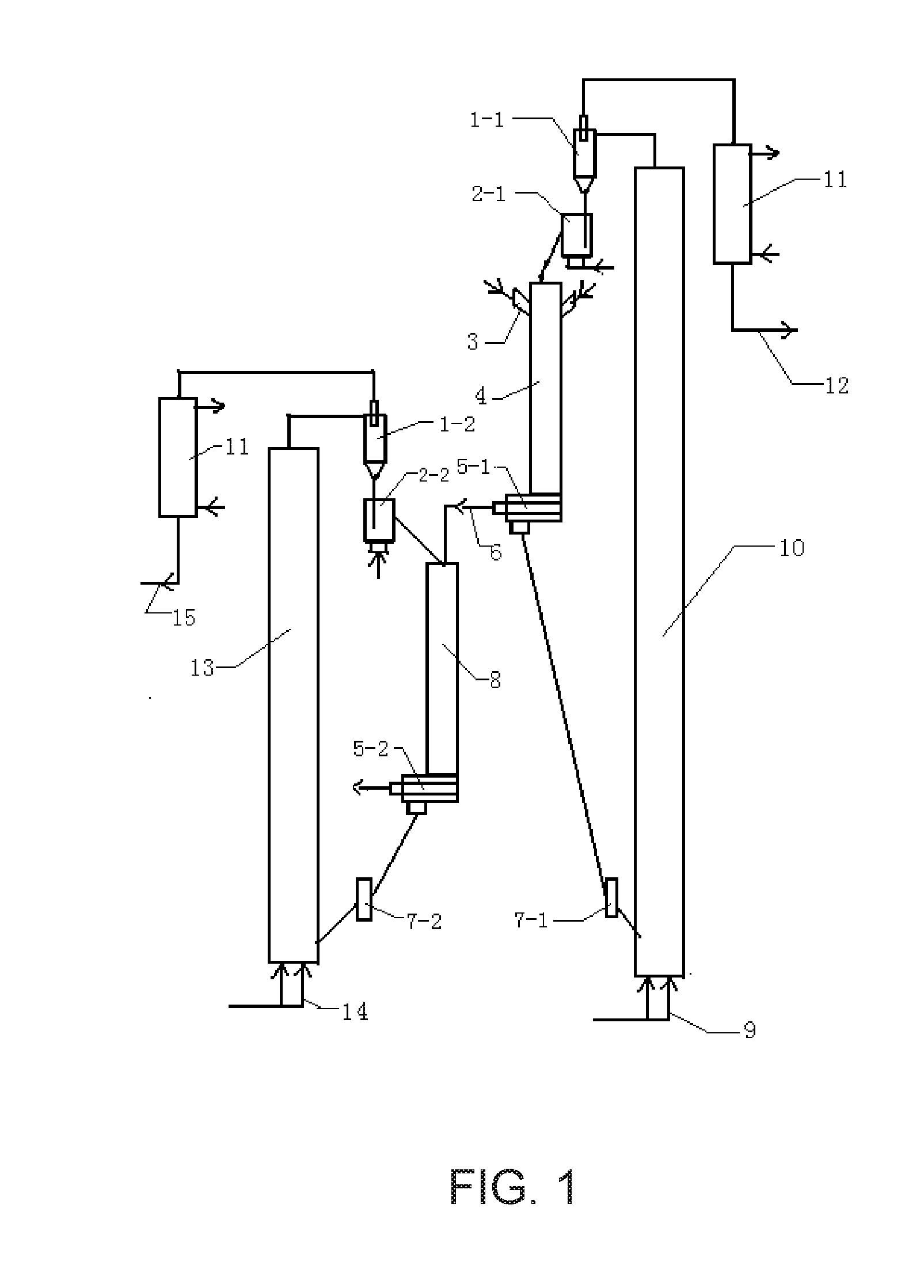
[0038] FIG. 1 is a schematic diagram of a technological process in the invention.
DESCRIPTION OF THE REFERENCE SIGNS
[0039] 1-1. first gas-solid separator;
[0040] 2-1. first return controller;
[0041] 3. high-efficiency atomizing nozzle;
[0042] 4. downflow modification reaction tube;
[0043] 5-1. first rapid gas-solid separator;
[0044] 6. pyrolysis gas outlet;
[0045] 7-1. first flow controller;
[0046] 8. millisecond cracking reactor;
[0047] 1-2. second gas-solid separator;
[0048] 2-2. second return controller;
[0049] 5-2. second rapid gas-solid separator;
[0050] 7-2. second flow controller;
[0051] 9. regenerant inlet;
[0052] 10. modification regeneration reactor;
[0053] 11. heat exchanger;
[0054] 12. regeneration gas outlet;
[0055] 13. crack regeneration reactor;
[0056] 14. air inlet;
[0057] 15. flue gas outlet.
[0058] The technological characteristics of the present invention will be described in detail below with reference to FIG. 1 and the embodiment examples.
DETAILED DESCRIPTION OF THE EMBODIMENTS
[0059] Each of the following examples specifies a process for producing low-carbon olefins by gaseous phase catalytic cracking of heavy oil with multi-stages in milliseconds according to the flow diagram shown in FIG. 1. The flow diagram shown in FIG. 1 specifically comprises:
[0060] 1) a high-efficiency atomizing nozzle 3 sprays the heavy oil preheated to 150.degree. C.-350.degree. C. from a feed inlet of a downflow modification reaction tube 4 into an upper portion of the downflow modification reaction tube 4, the produced oil mist is mixed with a high temperature solid heat carrier at a temperature ranging from 650.degree. C.-1,200.degree. C. flowing downward from a first return controller 2-1 for milliseconds, so as to heat, vaporize and pyrolyze the oil mist and obtain an oil and gas and a solid heat carrier to be regenerated, the pyrolysis reaction temperature is within a range of 480.degree. C.-850.degree. C.;
[0061] 2) the oil and gas as well as the solid heat carrier to be regenerated flow rapidly and downward to a first rapid gas-solid separator 5-1 at the bottom of the downflow modification reaction tube 4 to carry out a gas-solid separation to obtain a coked solid heat carrier to be regenerated and a high temperature oil and gas;
[0062] 3-1) the coked solid heat carrier to be regenerated flows through a first flow controller 7-1 and enters into a lower portion of a modification regeneration reactor 10 to conduct a regeneration reaction with a regeneration agent flowing is from a regenerant inlet 9, the temperature of the regeneration reaction is within a range of 680.degree. C.-1,250.degree. C.; the regeneration gas and high temperature solid heat carrier produced by the regeneration reaction are subject to a gas-solid separation in a first gas-solid separator 1-1 on top of the modification regeneration reactor 10, then the high temperature solid heat carrier with a carrier/oil ratio of 1-14 passes through the first return controller 2-1 and flows into a top of the downflow modification reaction tube 4 and enter into the downflow modification reaction tube 4 so as to participate in circulation and cracking of the heavy oil, the regeneration gas from the first gas-solid separator 1-1 is subject to heat exchange with a heat exchanger 11 and then output from a regeneration gas outlet 12;
[0063] 3-2) the high temperature oil and gas from the first rapid gas-solid separator 5-1 is not condensed but directly flowing in the gaseous phase into a millisecond cracking reactor 8 and mixing with a regeneration cracking catalyst having a temperature of 600.degree. C.-850.degree. C. from a second return controller 2-2 to carry out a gas phase catalytic cracking reaction, the temperature of cracking reaction temperature is within a range of 530.degree. C.-750.degree. C., then a cracking gas and a cracking catalyst to be regenerated produced by the cracking reaction pass through a second rapid gas-solid separator 5-2 to carry out a gas-solid separation in milliseconds;
[0064] 4-1) the cracking catalyst to be regenerated flows through a second flow controller 7-2 and enters a lower portion of the crack regeneration reactor 13 and perform a regeneration reaction with air flowing from an air inlet 14, the temperature of the regeneration reaction is 630.degree. C.-900.degree. C., the obtained flue gas and the high temperature crack catalyst are subject to a gas-solid separation in a second gas-solid separator 1-2 at the top of the crack regeneration reactor 13; the high temperature crack catalyst with a catalyst/oil ratio of 1-8 passes through the second return controller 2-2 and flows into the millisecond cracking reactor 8 to participate the circulation reaction; and the flue gas is subject to heat exchange with a heat exchanger 11 and then output from a flue gas outlet 15;
[0065] 4-2) the cracking oil and gas produced by the cracking reaction enter into the subsequent separation devices to separate out the low carbon olefins and aromatic hydrocarbons.
[0066] The first gas-solid separator 1-1 on top of the modified regeneration reactor and is the second gas-solid separator 1-2 on top of the crack regeneration reactor may be identical or different, and are one selected from the group consisting of an inertial separator, a horizontal cyclone separator, and a vertical cyclone, respectively.
[0067] The first rapid gas-solid separator 5-1 at the bottom of the downflow modification reaction tube 4 and the second rapid gas-solid separator 5-2 at the bottom of the millisecond cracking reactor 8 may be identical or different, and are one selected from the group consisting of an inertial separator and a horizontal cyclone separator, respectively.
[0068] In the following examples and comparative examples, the calculation formula of a yield of low carbon olefins is as follows:
[0069] The yield of low carbon olefins=a total yield of three olefins (i.e., "ethylene, propylene and butane")
[0070] Both of the fisrt gas-solid separator and the second gas-solid separator use a vertical cyclone; both of the fisrt rapid gas-solid separator and the second rapid gas-solid separator use a horizontal cyclone separator.
[0071] Both the modified regeneration reactor and the crack regeneration reactor are riser regenerators.
[0072] The millisecond cracking reactor is a downflow tube reactor.
EXAMPLE 1
[0073] The inferior heavy oil treated in the example is a vacuum residue oil of Shengli thickened oil, and its residual carbon content is 15%. The key property parameters are shown in Table 1:
TABLE-US-00001 TABLE 1 Density (kg/m.sup.3, 20.degree. C.) 1,002.1 Viscosity (mm s.sup.-1, 100.degree. C.) 671 Residual carbon content (wt. %) 15.0 Carbon content (wt. %) 86.2 Hydrogen content (wt. %) 6.8
[0074] The solid heat carrier is calcium aluminate porous microspheres having a particle size ranging from 15 to 150 micrometers.
[0075] The cracking catalyst is a shape selective molecular sieve catalyst, specifically ZSM-5 catalyst having a particle size ranging from 15 to 150 microns.
[0076] The process flow is as follows:
[0077] 1) the inferior heavy oil preheated to 200.degree. C. is sprayed from a feed inlet of a downflow modification reaction tube 4 into an upper portion of the downflow modification reaction tube 4, the produced oil mist is mixed with a high temperature solid heat carrier (calcium aluminate porous microspheres) having a temperature 950.degree. C. flowing downward from the first return controller 2-1 for milliseconds, so as to heat, vaporize and pyrolyze the heavy oil, the pyrolysis reaction temperature is 510.degree. C.;
[0078] 2) the oil and gas as well as the solid heat carrier to be regenerated flow rapidly and downward to the bottom of the downflow modification reaction tube 4 to carry out a gas-solid separation;
[0079] 3-1) the coked solid heat carrier to be regenerated enters into a modification regeneration reactor 10 to conduct a regeneration reaction with air at the temperature of 970.degree. C.; the regeneration gas and high temperature solid heat carrier produced by the regeneration reaction are subject to a gas-solid separation, then the high temperature solid heat carrier with a carrier/oil ratio of 10 returns to the downflow modification reaction tube 4 so as to participate in circulation and cracking of the heavy oil, the regeneration gas is subject to heat exchange and then output;
[0080] 3-2) the high temperature oil and gas in the downflow modification reaction tube 4 is not condensed but directly flowing in the gaseous phase into the millisecond cracking reactor 8 and mixing with the regeneration cracking catalyst (ZSM-5 catalyst) having a temperature of 800.degree. C. to carry out a gas phase catalytic cracking reaction, the temperature of cracking reaction temperature is 730.degree. C., then the cracking gas and the cracking catalyst to be regenerated carry out a gas-solid separation in milliseconds;
[0081] 4-1) the cracking catalyst to be regenerated enters the crack regeneration reactor 13 and perform a regeneration reaction with air at the temperature of 800.degree. C., the obtained flue gas and the high temperature crack catalyst are subject to a gas-solid separation; then the high temperature crack catalyst with a catalyst/oil ratio of 6 returns to the millisecond cracking reactor 8 to participate the circulation reaction; while the flue gas is subject to heat exchange and then output;
[0082] 4-2) the cracking oil and gas produced by the cracking reaction are subject to the subsequent separation to produce the low carbon olefins and aromatic hydrocarbons respectively.
[0083] The results show that the process in Example 1 has a total yield of three olefins (i.e., "ethylene, propylene and butane") up to 37% for inferior heavy oil having a residual carbon content of 15%, wherein the yields of propylene and ethylene are 20% and 12%, respectively.
COMPARATIVE EXAMPLE 1
[0084] This comparative example is used to illustrate the process of preparing three olefins from the catalytic cracking of pyrolyzed wax oil.
[0085] The above-mentioned inferior heavy oil in Example 1 is initially subject to a delayed coking to obtain 4% of coking liquefied gas, 13.5% of coking gasoline, 27% of coking diesel, 30% of coking wax oil, 22.5% of coke, and 3% of coking dry gas by weight.
[0086] The solid heat carrier is calcium aluminate porous microspheres having a particle size ranging from 15 to 150 micrometers.
[0087] The key property parameters of the coking wax oil are shown in Table 2.
TABLE-US-00002 TABLE 2 Density (kg/m.sup.3, 20.degree. C.) 890.5 Viscosity (mm s.sup.-1, 100.degree. C.) 21 Residual carbon content (wt. %) 2.3 Carbon content (wt. %) 82.5 Hydrogen content (wt. %) 7.8
[0088] The process flow of preparing three olefins (i.e., "ethylene, propylene and butane") from the catalytic cracking of pyrolyzed wax oil is as follows:
[0089] 1) the coking wax oil preheated to 200.degree. C. is sprayed from a feed inlet of a downflow modification reaction tube into an upper portion of the downflow modification reaction tube, the produced oil mist is mixed with a high temperature solid heat carrier (calcium aluminate porous microspheres) at a temperature 950.degree. C. flowing downward from the first return controller for milliseconds, so as to heat, vaporize and pyrolyze the coking wax oil, the pyrolysis reaction temperature is 550.degree. C.;
[0090] 2) the oil and gas as well as the solid heat carrier to be regenerated flow rapidly and downward to the bottom of the downflow reaction tube to carry out a gas-solid separation;
[0091] 3) the coked solid heat carrier to be regenerated enters into a regeneration reactor to conduct a regeneration reaction with air at the temperature of 970.degree. C.; the regeneration gas and high temperature solid heat carrier produced by the regeneration reaction are subject to a gas-solid separation, then the high temperature solid heat carrier with a carrier/oil ratio of 10 returns to the downflow reaction tube so as to participate in circulation and pyrolyze of the coking wax oil, the regeneration gas is subject to heat exchange and then output;
[0092] 4) the high temperature oil and gas in the downflow reaction tube are subject to the subsequent separation to produce the low carbon olefins and aromatic hydrocarbons respectively.
[0093] The results show that a total yield of three olefins (i.e., "ethylene, propylene and butane") prepared from the catalytic cracking of pyrolyzed wax oil is 33%, io wherein the yields of propylene and ethylene are 16% and 14%, respectively. If calculated according to the heavy oil, the total yield of three olefins obtained by this process is only about 10%.
[0094] It is demonstrated from a comparison of Example 1 of the invention with Comparative example 1 that the process of the invention can obtain a higher yield is of three olefins, and avoids that the reheating, temperature rise and atomization of the wax oil in the traditional combined process of pyrolysis modification--wax oil catalytic cracking, but it still has a common problem, namely the "cage effect" of the liquid phase reaction results in an increased condensation polymerization, thereby reducing the yield and selectivity of low carbon olefins.
[0095] In addition, the invention has a short processing procedure, which is specifically reflected that it is not necessary for the crude oil subjecting to electric desalting and atmospheric pressure and vacuum distillation treatments, and the crude oil is directly used as a feedstock of the catalytic cracking, the steel consumption of the apparatus is low, the fixed investment is greatly reduced; the atmospheric pressure operation is simple, it is convenient to start or shut down the apparatus, the operational continuity is desirable, and the apparatus has strong adaptability for processing a variety of oils.
EXAMPLE 2
[0096] The inferior heavy oil is identical with that in Example 1.
[0097] The solid heat carrier is aluminum silicate porous microsphere having a particle size ranging from 15 to 150 micrometers.
[0098] The cracking catalyst is a ZSM-5 molecular sieve catalyst having a particle size ranging from 15 to 150 micrometers.
[0099] 1) The inferior heavy oil preheated to 150.degree. C. is sprayed from a feed inlet of a downflow modification reaction tube 4 into an upper portion of the downflow modification reaction tube 4, the produced oil mist is mixed with a high temperature solid heat carrier (aluminum silicate porous microspheres) having a temperature 900.degree. C. flowing downward from the first return controller 2-1 for milliseconds, so as to heat, vaporize and pyrolyze the heavy oil, the pyrolysis reaction temperature is 580.degree. C.;
[0100] 2) the oil and gas as well as the solid heat carrier to be regenerated flow rapidly and downward to the bottom of the downflow modification reaction tube 4 to carry out a gas-solid separation;
[0101] 3-1) the coked solid heat carrier to be regenerated enters into a modification is regeneration reactor 10 to conduct a regeneration reaction with air at the temperature of 920.degree. C.; the regeneration gas and high temperature solid heat carrier produced by the regeneration reaction are subject to a gas-solid separation, then the high temperature solid heat carrier with a carrier/oil ratio of 5 returns to the downflow modification reaction tube 4 so as to participate in circulation and cracking of the heavy oil, the regeneration gas is subject to heat exchange and then output;
[0102] 3-2) the high temperature oil and gas in the downflow modification reaction tube 4 is not condensed but directly flowing in the gaseous phase into the millisecond cracking reactor 8 and mixing with the regeneration cracking catalyst (ZSM-5 catalyst) having a temperature of 700.degree. C. to carry out a gas phase catalytic cracking reaction, the temperature of cracking reaction temperature is 620.degree. C., then the cracking gas and the cracking catalyst to be regenerated carry out a gas-solid separation in milliseconds;
[0103] 4-1) the cracking catalyst to be regenerated enters the crack regeneration reactor 13 and perform a regeneration reaction with air at the temperature of 800.degree. C., the obtained flue gas and the high temperature crack catalyst are subject to a gas-solid separation; then the high temperature crack catalyst with a catalyst/oil ratio of 4 returns to the millisecond cracking reactor 8 to participate the circulation reaction; and the flue gas is subject to heat exchange and then output;
[0104] 4-2) the crack oil and gas produced by the cracking reaction are subject to the subsequent separation to produce the low carbon olefins and aromatic hydrocarbons respectively.
[0105] The results show that the process in Example 2 has a total yield of three olefins (i.e., "ethylene, propylene and butane") up to 45% for inferior heavy oil having a residual carbon content of 15%, wherein the yields of propylene and ethylene are 25% and 16%, respectively.
COMPARATIVE EXAMPLE 2
[0106] The inferior heavy oil is treated according to the process of Example 1, except that the high temperature solid heat carrier with a carrier/oil ratio of 16 is controlled to pass through the first return controller and flow into a top of the is downflow modification reaction tube and enter into the reaction to participate circulation and cracking of the heavy oil.
[0107] The result reveals that a total yield of three olefins (i.e., "ethylene, propylene and butane") reaches 33%, wherein the yields of propylene and ethylene are 16% and 11%, respectively.
COMPARATIVE EXAMPLE 3
[0108] The inferior heavy oil is treated according to the process of Example 1, except that the high temperature solid heat carrier with a carrier /oil ratio of 0.5 is controlled to pass through the first return controller and flow into a top of the downflow modification reaction tube and enter into the reaction to participate circulation and cracking of the heavy oil.
[0109] The result reveals that a total yield of three olefins (i.e., "ethylene, propylene and butane") is 35%, wherein the yields of propylene and ethylene are 18% and 13%, respectively.
COMPARATIVE EXAMPLE 4
[0110] The inferior heavy oil is treated according to the process of Example 1, except that the pyrolysis reaction temperature is controlled to be 1,000.degree. C.
[0111] The result reveals that a total yield of three olefins (i.e., "ethylene, propylene and butane") is 30%, wherein the yields of propylene and ethylene are 16% and 12%, respectively.
EXAMPLE 3
[0112] The inferior heavy oil processed in the example is identical with that in Example 1.
[0113] The solid heat carrier is the porous microsphere carrier loaded with sodium(Na), the porous microsphere carrier has a particle size ranging from 15 to 150 micrometers.
[0114] The cracking catalyst is a FCC molecular sieve catalyst having a particle size ranging from 15 to 150 micrometers.
[0115] 1) The inferior heavy oil preheated to 300.degree. C. is sprayed from a feed inlet of a downflow modification reaction tube 4 into an upper portion of the downflow modification reaction tube 4, the produced oil mist is mixed with a high temperature solid heat carrier (porous microsphere carrier loaded with sodium) having a temperature 800.degree. C. flowing downward from the first return controller 2-1 for milliseconds, so as to heat, vaporize and pyrolyze the heavy oil, the pyrolysis reaction temperature is 660.degree. C.;
[0116] 2) the oil and gas as well as the solid heat carrier to be regenerated flow rapidly and downward to the bottom of the downflow modification reaction tube 4 to carry out a gas-solid separation; 3-1) the coked solid heat carrier to be regenerated enters into a modification regeneration reactor 10 to conduct a regeneration reaction with air at the temperature of 1,120.degree. C.; the regeneration gas and high temperature solid heat carrier produced by the regeneration reaction are subject to a gas-solid separation, then the high temperature solid heat carrier with a carrier/oil ratio of 12 returns to the downflow modification reaction tube 4 so as to participate in circulation and cracking of the heavy oil, the regeneration gas is subject to heat exchange and then output; 3-2) the high temperature oil and gas in the downflow modification reaction tube 4 is not condensed but directly flowing in the gaseous phase into the millisecond cracking reactor 8 and mixing with the regeneration cracking catalyst (FCC molecular sieve) having a temperature of 700.degree. C. to carry out a gas phase catalytic cracking reaction, the temperature of cracking reaction temperature is 720.degree. C., then the cracking gas and the cracking catalyst to be regenerated carry out a gas-solid separation in milliseconds;
[0117] 4-1) the cracking catalyst to be regenerated enters the crack regeneration reactor 13 and perform a regeneration reaction with air at the temperature of 830.degree. C., the obtained flue gas and the high temperature crack catalyst are subject to a gas-solid separation; then the high temperature crack catalyst with a catalyst/oil ratio of 1 returns to the millisecond cracking reactor 8 to participate the circulation reaction; and the flue gas is subject to heat exchange and then output;
[0118] 4-2) the cracking oil and gas produced by the cracking reaction are subject to the subsequent separation to produce the low carbon olefins and aromatic hydrocarbons respectively.
[0119] The results show that the process in Example 2 has a total yield of three olefins (i.e., "ethylene, propylene and butane") up to 37% for inferior heavy oil, wherein the yields of propylene and ethylene are 16% and 18%, respectively.
[0120] The invention provides a process for producing low-carbon olefins by gaseous phase catalytic cracking of heavy oil with multi-stages in milliseconds, the process utilizes a rapid alkaline catalytic pyrolysis of the inferior heavy oil to maximize production of the oil and gas, this high temperature oil and gas is used for preparing low carbon olefins by directly subjecting to high temperature millisecond shape selective catalytic cracking instead of subjecting to the condensation and separation, thereby fully utilizing heat of the pyrolysis oil and gas; the process overcomes the "cage effect" of the liquid phase reaction, reduces an influence of heat and mass transfer on catalytic cracking, and greatly decreases the amount of generated coke and energy consumption in the cracking process; the reaction temperature and time may be easily adjusted and controlled, and the characteristic that the alkaline catalytic pyrolysis of heavy oil produces a large amount of olefins may be used for shape selective catalysis , thereby significantly improving the yield and selectivity of low carbon olefins.
* * * * *
D00000
D00001
XML
uspto.report is an independent third-party trademark research tool that is not affiliated, endorsed, or sponsored by the United States Patent and Trademark Office (USPTO) or any other governmental organization. The information provided by uspto.report is based on publicly available data at the time of writing and is intended for informational purposes only.
While we strive to provide accurate and up-to-date information, we do not guarantee the accuracy, completeness, reliability, or suitability of the information displayed on this site. The use of this site is at your own risk. Any reliance you place on such information is therefore strictly at your own risk.
All official trademark data, including owner information, should be verified by visiting the official USPTO website at www.uspto.gov. This site is not intended to replace professional legal advice and should not be used as a substitute for consulting with a legal professional who is knowledgeable about trademark law.