Insulated Package
Gray; Eric ; et al.
U.S. patent application number 16/385657 was filed with the patent office on 2019-10-17 for insulated package. This patent application is currently assigned to Craft Packaging LLC. The applicant listed for this patent is Craft Packaging LLC. Invention is credited to Eric Gray, Travis Winn.
| Application Number | 20190315541 16/385657 |
| Document ID | / |
| Family ID | 68160685 |
| Filed Date | 2019-10-17 |


| United States Patent Application | 20190315541 |
| Kind Code | A1 |
| Gray; Eric ; et al. | October 17, 2019 |
INSULATED PACKAGE
Abstract
This disclosure generally describes a method, system, and device for constructing a packaging device and the package itself. The packaging device includes one or more insulative interlocking panels which are affixed to one or more corresponding panels of packaging material. The insulative interlocking panels may be assembled together into an insulative packaging device surrounded by packaging material.
| Inventors: | Gray; Eric; (Draper, UT) ; Winn; Travis; (Draper, UT) | ||||||||||
| Applicant: |
|
||||||||||
|---|---|---|---|---|---|---|---|---|---|---|---|
| Assignee: | Craft Packaging LLC Draper UT |
||||||||||
| Family ID: | 68160685 | ||||||||||
| Appl. No.: | 16/385657 | ||||||||||
| Filed: | April 16, 2019 |
Related U.S. Patent Documents
| Application Number | Filing Date | Patent Number | ||
|---|---|---|---|---|
| 62658428 | Apr 16, 2018 | |||
| Current U.S. Class: | 1/1 |
| Current CPC Class: | B65D 65/44 20130101; B65D 85/30 20130101; B65D 81/127 20130101; B65D 81/3823 20130101; B65D 11/1873 20130101; B65D 2581/051 20130101; B65D 81/025 20130101 |
| International Class: | B65D 81/02 20060101 B65D081/02; B65D 81/127 20060101 B65D081/127; B65D 6/24 20060101 B65D006/24 |
Claims
1. A package, comprising: a box cutout having a plurality of panels and a plurality of insulative panels, each of the plurality of insulated panels being affixed to one of the plurality of panels.
2. The package of claim 1, wherein an edge of each one of the insulated panels mates with an edge of another one of the insulated panels.
3. The package of claim 2, wherein the edge of each one of the insulated panels includes a lock.
4. The package of claim 3, wherein the edge of each one of the insulated panels are interlocking with the edge of the another one of the insulated panels.
5. The package of claim 2, wherein the edge of each one of the insulated panels has a complimentary angle to the edge of the another one of the insulated panels.
6. The package of claim 2, wherein the edge of each one of the insulated panels is beveled at a complimentary angle to the edge of the another one of the insulated panels.
7. The package of claim 1, wherein the box cutout is a packing backing material.
8. The package of claim 7, wherein the packing backing material is cardboard.
9. The package of claim 7, wherein the packing backing material is corrugated cardboard.
10. The package of claim 7, wherein the packing backing material is corrugated plastic.
11. The package of claim 1, wherein the box cutout is a cutout for a square box.
12. The package of claim 1, wherein the box cutout is a cutout for a rectangular box.
13. The package of claim 1, wherein the package is flat.
14. The package of claim 1, wherein the package is assembled into an insulated box.
15. The package of claim 13, wherein the insulated box includes a cavity.
16. The package of claim 1, wherein the plurality of insulated panels are foam panels.
17. The package of claim 15, wherein the foam panels include a reflective surface.
18. The package of claim 15, wherein the foam panels have an insulation value that exceeds R4.
19. The package of claim 1, wherein the plurality of insulated panels are air bladders.
20. A system, comprising: a box cutout having a plurality of panels and a plurality of insulative panels, each of the plurality of insulated panels being affixed to one of the plurality of panels.
Description
CROSS-REFERENCE TO RELATED APPLICATIONS
[0001] This application claims the benefit of U.S. Provisional Application No. 62/658,428, filed Apr. 16, 2018, which is incorporated herein by reference in its entirety, including but not limited to those portions that specifically appear hereinafter, the incorporation by reference being made with the following exception: In the event that any portion of the above-referenced provisional application is inconsistent with this application, this application supersedes said above-referenced provisional application.
BACKGROUND
1. Technical Field
[0002] This disclosure relates generally to a system, device, and method of making an insulated packaging device which includes one or more interlocking panels of insulated material, affixed to the sides of a box. In one embodiment, the insulated packaging device includes a box cutout which lays essentially flat and to which various interlocking panels of insulative material are affixed, such that when the box cutout is assembled, the box cutout and the interlocking panels of insulative material are assembled into an insulated packing box to maintain a temperature of an item placed in the insulated packing box.
2. Description of the Related Art
[0003] Since the advent of the trade of goods over long distances, man has been designing various containers and vessels for transporting the goods while ensuring that the goods arrive at their destination in the same unspoiled condition in which they were shipped. Historically, spices, for example, were contained within an earthenware container and placed in a wood box or crate loaded with straw as packing material with the intent that the straw would absorb shock that may be encountered during shipping of the spices and prevent the earthenware container from breaking during transport.
[0004] Until around the advent of air travel, most packaging of various breakable goods to be protected was straw, or cotton, or some other natural compressible and soft material. However, when airplanes began to travel across the world in less than a day, trade changed and the things that could be shipped changed along with it. For example, with an airplane, a crate of fruit could be shipped from warm weather climates to cold weather climates such that fresh fruit of virtually any variety became available all year long. Similarly, beef farmed on another continent could be butchered and packed in a container on ice to be prepared on another continent in less time than it took the ice in the container to melt.
[0005] One difficulty in shipping has always been shipping temperature sensitive items from one place to another. Before the advent of the steam engine, it was virtually impossible to transport any temperature sensitive items any meaningful distance except during an appropriate season. For example, fresh oysters harvested on the Eastern Shore of Virginia were transported by rail to market only during winter months when shippers could be assured that the product would not be tainted by heat. During summer months, only canned oysters could be shipped because the canning process protected the oysters from heat they would be exposed to during transport. Occasionally, fresh oysters could be shipped in the summer months in small quantities if an ice box and sufficient ice were available on a train.
[0006] Even today, ice boxes, known as coolers, are the most common form of keeping food (or other temperature sensitive items) cold in situations where electricity is not available. Each new cooler company clamors to redesign coolers to produce more insulative, more transportable, more rigid coolers to protect temperature sensitive items at their proper temperature (either cold or hot). However, these various cooler designs have become, in at least some situations, outrageously expensive requiring a long serviceable lifespan to make an investment in such a cooler worthwhile. Thus, these coolers are unsuitable for shipping because of the high cost of purchase and, in many cases, the weight of such coolers.
[0007] For shipping and packaging situations, it became necessary to create a cooler that was light, inexpensive, insulative for temperature sensitive items, and rigid enough to survive the shipping process. The generally accepted solution to these issues became lidded boxes made from a closed-cell extruded polystyrene foam ("EPS foam"), also known as Styrofoam.RTM.. EPS foam has not only been used within conventional coolers as insulation, but also has been molded into boxes which serve as effective temporary coolers when combined with a molded lid that closes the box. For shipping purposes, these EPS foam boxes are typically installed within a cardboard box for transportation. Airlines have specifically approved certain box/EPS foam coolers as baggage to transport seafood, for example. In one example, these box/EPS foam coolers are ubiquitous in Alaska during the summer fishing season, to allow many sport fishermen to return home with their prized catches safely contained and cold within these box/EPS foam coolers.
[0008] FIG. 1 illustrates one of these prior art cardboard box/EPS foam coolers 100. As shown in FIG. 1, a corrugated cardboard box 105 is provided along with a molded EPS foam cooler box 110. Corrugated cardboard box 105 includes a recess 115 which is sized virtually precisely to receive EPS foam cooler box 110 inside recess 115 of corrugated cardboard box 105. EPS foam cooler box 110 further includes a recess 120 which may contain temperature sensitive items, such as fillets from a prized chinook salmon caught by a sport fisherman in Alaska, for example. EPS foam cooler box 110 may include a lid 125 which may enclose the prized chinook salmon fillets inside recess 120 of EPS foam cooler box 110 along with frozen gel packs to provide an insulated cool box which can be safely shipped for up to 24 hours before refreshing the frozen gel packs.
[0009] FIG. 2A illustrates an embodiment of a cardboard box/EPS foam cooler 200 which provides additional insulation and shock protection over cardboard box/EPS foam cooler 100, shown in FIG. 1, for more sensitive items (in terms of temperature and physical shock) than salmon fillets, such as, for example, human organs. Cardboard box/EPS foam cooler 200 includes a cardboard box 205, and an EPS foam cooler box 210 disposed inside cardboard box 205. However, in FIG. 2A, a secondary layer of insulative and or protective material 215 is installed around EPS foam cooler 210. For example, foam peanuts or packing peanuts may be layered between cardboard box 205 and EPS foam cooler 210. Foam peanuts may also be formed using expanded polystyrene, providing further insulation while also providing cushioning by virtue of their respective shapes. The foam peanuts are designed to nest because of their respective shapes when compressed and to freely move when uncompressed which is an efficient method to absorb shock during shipping, for example.
[0010] Otherwise, EPS foam cooler 210 is similar to EPS foam cooler 110, shown in FIG. 1, and includes a cavity 220 for enclosing a temperature sensitive and shock sensitive item inside EPS foam cooler 210. EPS foam cooler 210 may also include a molded lid which connects to a lip of EPS foam cooler 210 in a manner that tends to retain lid 225 on EPS foam cooler 210.
[0011] Once the temperature sensitive items have been placed within cavity 220 of foam cooler 210 and lid 225 installed on a lip of EPS foam cooler 210, cardboard box/EPS foam cooler 200 may be prepared for shipping, as shown in FIG. 2B. FIG. 2B illustrates cardboard box 205, EPS foam cooler 210 and insulative/protective layer 215 assembled together with lid 225 to provide a cavity 220 for containing temperature sensitive items within cardboard box/EPS foam cooler 200. Cardboard box 205 has been closed using various flaps to ensure that cardboard box 205 completely encloses EPS foam cooler 210. At this point, cardboard box/EPS foam cooler 200 are safely installed and ready for shipping.
[0012] One unexpected aspect of the prior art technologies shown in FIG. 1, FIG. 2A and FIG. 2B is the storage space required to store foam box 210 and lid 225. For many retailers, entire warehouses are filled with foam boxes, such as foam box 210, which themselves are empty, waiting to portage a prized chinook salmon fillet from Alaska to Texas, for example. Standard airline approved cardboard box/EPS foam coolers may be approximately 18'' wide, 18'' deep and 30'' long. Thus, when stacked one on top of another, these cardboard box/EPS foam coolers may be stacked 8 or 9 units high before a person of average height can no longer stack further units on top without a ladder, for example. Thus, one drawback of these prior art technologies is that the foam coolers are spatially inefficient and incur significant storage cost to store until sold.
[0013] Further, it should be noted that many of these prior art technologies are first shipped to, Alaska, for example, on container ships or other conveyance as full 18''.times.18''.times.28'' boxes which requires significant amounts of space on a container ship. Thus, not only is the amount of space required to store these prior art technologies oppressive but shipping these prior art technologies to their respective storage locations is also a spatially intense undertaking. Simply put, space constraints minimize the number of cardboard box/EPS foam coolers that can be shipped at a price that makes their use as a shipping package feasible.
[0014] Accordingly, it is one object of this disclosure to provide a packaging system that includes interlocking insulative panels that may be assembled into a package. It is another object of this disclosure to provide a device which includes interlocking insulative panels affixed to a box cutout which may lay substantially flat during shipping to a storage destination, but which may be assembled into a box/EPS foam cooler when needed. It is another object of this disclosure to provide a method of making a shipping container with interlocking panels affixed to a box cutout.
SUMMARY
[0015] Disclosed herein is a package. The package includes a box cutout having a plurality of panels. The package further includes a plurality of insulative panels, each of which are affixed to one of the plurality of panels of the box cutout.
BRIEF DESCRIPTION OF THE DRAWINGS
[0016] The accompanying drawings illustrate various embodiments of an insulated packaging system disclosed herein.
[0017] FIG. 1 illustrates a prior art cardboard box/EPS foam cooler.
[0018] FIG. 2A illustrates another prior art embodiment of a cardboard box/EPS foam cooler.
[0019] FIG. 2B illustrates another prior art embodiment of a cardboard box/EPS foam cooler prepared for shipping.
[0020] FIG. 3 illustrates one exemplary insulated packaging system which includes insulative interlocking panels affixed to a box cutout.
[0021] FIG. 4 illustrates the exemplary insulated packaging system of FIG. 3 which includes insulative interlocking panels affixed to a box cutout in an assembled condition.
[0022] FIG. 5 illustrates an alternative exemplary insulated packaging system which includes insulative interlocking panels affixed to a box cutout.
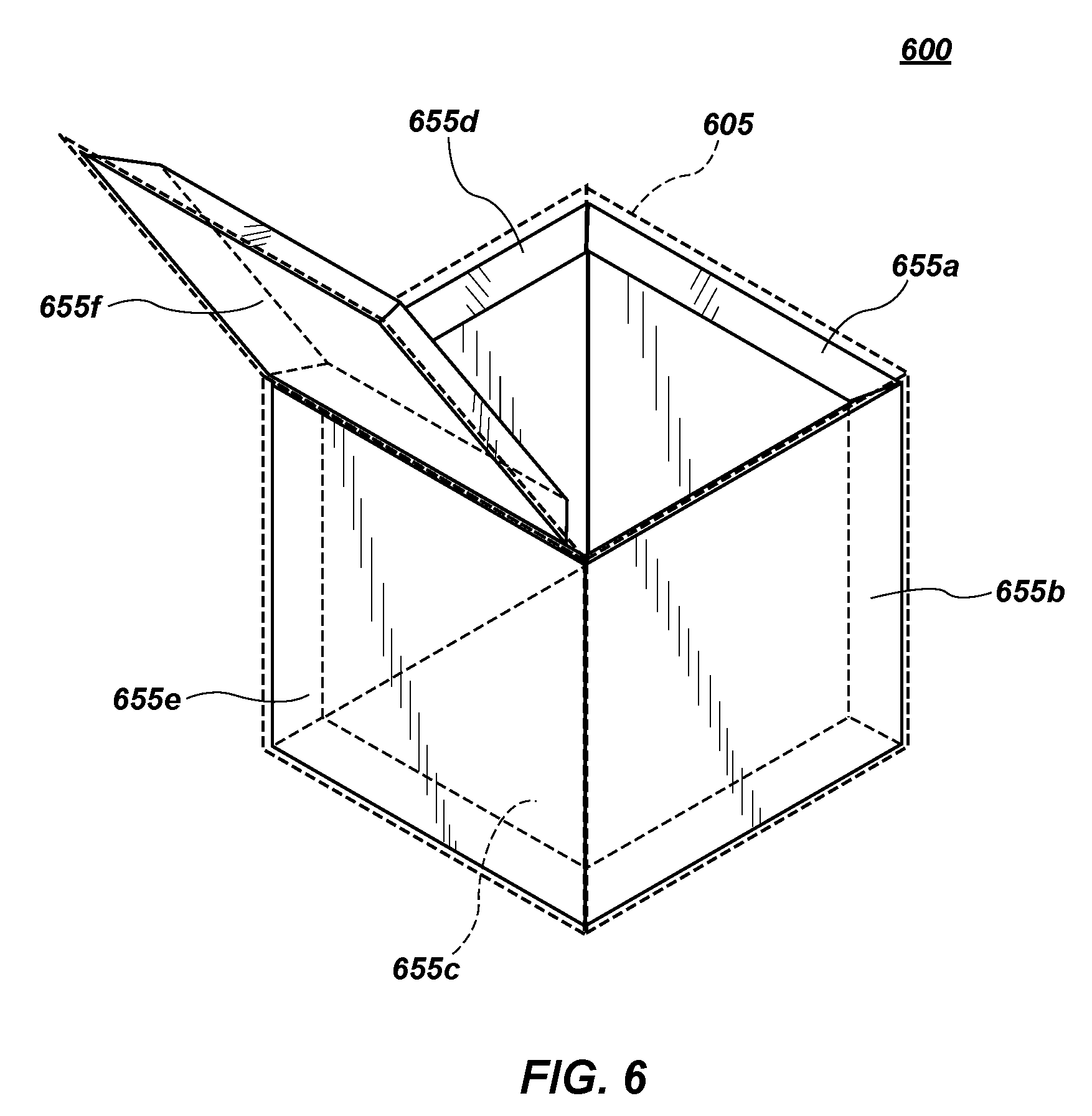
[0023] FIG. 6 illustrates the exemplary insulated packaging system of FIG. 5 which includes insulative interlocking panels affixed to a box cutout in an assembled condition.
DETAILED DESCRIPTION OF PREFERRED EMBODIMENTS
[0024] In the following description, for purposes of explanation and not limitation, specific techniques and embodiments are set forth, such as particular techniques and configurations, in order to provide a thorough understanding of the device disclosed herein. While the techniques and embodiments will primarily be described in context with the accompanying drawings, those skilled in the art will further appreciate that the techniques and embodiments may also be practiced in other similar devices.
[0025] Reference will now be made in detail to the exemplary embodiments, examples of which are illustrated in the accompanying drawings. Wherever possible, the same reference numbers are used throughout the drawings to refer to the same or like parts. It is further noted that elements disclosed with respect to particular embodiments are not restricted to only those embodiments in which they are described. For example, an element described in reference to one embodiment or figure, may be alternatively included in another embodiment or figure regardless of whether or not those elements are shown or described in another embodiment or figure. In other words, elements in the figures may be interchangeable between various embodiments disclosed herein, whether shown or not.
[0026] FIG. 3 illustrates an alternative exemplary insulated packaging system 300 which includes insulative interlocking panels 355a-355f affixed to a box cutout 305. Box cutout 305 may be cut into a form that may be easily shaped into a box, for example, and made of any conventional packaging material such as paper, cardstock, cardboard, corrugated cardboard, plastics (rigid or soft), corrugated plastic, or any other conventional packaging backing material. Box cutout 305 is formed in such a shape as to form a square box having six sides. It is noted, however, that a square box is only one possible implementation of insulated packaging system 300. Insulated packaging system 300 may be implemented in any three-dimensional shape when assembled, including whimsical shapes, as desired for any particular implementation. For example, insulated packaging system 300 may form a rectangular box, a spherical box, a tetrahedral box, a box having any number of sides, or may, in some shapes be formed to represent cartoon characters, fictional characters, representations of fantastical creatures, or any other implementation that may be desirable for a package. However, for purposes of explanation, insulated packaging system 300 is shown as a box cutout 305 which may be assembled into a six-sided square box.
[0027] Box cutout 305 may include a plurality of panels 360a-360f which form the six sides of the exemplary square box. Box cutout 305 may further include pre-installed creases or indentations to facilitate assembly of insulated packaging system 300. For example, box cutout 305 may include a first vertical crease 310 and a second vertical crease 315 which extend along a length of box cutout 305 to facilitate assembly of the other various panels, tabs, and flaps of insulated packaging system 300, as will be discussed below. Similarly, box cutout 305 may include a first horizontal crease 320, a second horizontal crease 325, a third horizontal crease 330, and a fourth horizontal crease 335 which extend along a width of box cutout 305 to facilitate assembly of the other various panels, tabs, and flaps of insulated packaging system 300, as will be discussed below.
[0028] Some of the other various panels, tabs, and flaps on box cutout 305 may include a first support tab 340 and a second support tab 345 which serve to add structural rigidity to insulated packaging system 300 when assembled into an exemplary six-sided square box. box cutout 305 may further include a plurality of flaps, such as flaps 350a-350d which may be used to provide access points into or provide structural rigidity for insulated packaging system 300 when assembled into an exemplary six-sided square box. For example, flaps 350a-350d may fold over a top or bottom portion of insulated packaging system 300 and be connected together by, for example, packaging tape, that is used to seal insulated packaging system 300 when assembled into an exemplary six-sided box.
[0029] box cutout 305 may further include one or more interlocking insulative panels 355a-355f affixed in a permanent manner to panels 360a-360f. Interlocking insulative panels 355a-355f may be constructed from EPS foam and formed into panels that have male and female interlocking parts, in this embodiment. More simply, interlocking insulative panels 355a-355f may include one or more locks that connect at least one of interlocking insulative panels 355a-355f to at least one other of interlocking insulative panels 355a-355f. Alternatively, interlocking insulative panels 355a-355f may include one or more locks that connect to each adjacent one of interlocking insulative panels 355a-355f. One example of a lock may include a male connection in one of interlocking insulative panels 355a-355f which corresponds to a female recess of appropriate size and shape in another of interlocking insulative panels 355a-355f to receive the male connection. Another example of a lock may include interlocking insulative panels 355a-355f having edge portions that are cut or beveled into complimentary angles such that each of the interlocking insulative panels 355a-355f fits squarely into a recess created by corresponding beveled angles in adjacent interlocking insulative panels 355a-355f. Interlocking insulative panels 355a-355f may be fashioned in any number of possible configurations to facilitate interlocking of panels. These examples are merely representative of these possible configurations. It should also be noted that interlocking panels need not necessarily include male and female interlocking portions to be considered interlocking. For example, in the embodiment shown in FIG. 3, interlocking insulative panels 355a-355f may be implemented as simple squares having flat square surfaces around the periphery of the insulative panel. In this manner, when box cutout 305 is assembled, insulative panels 355a-355f may merely butt against other panels (e.g., mating 90.degree. edges), forming an insulated cube inside an assembled box cutout 305. Optionally, insulative panels that butt against other panels may include an adhesive to seal the panels to each other in an assembled state to prevent leaking or condensation. For purposes of this disclosure, an "interlocking" insulative panel is intended to describe any insulative panel affixed to a box cutout that may include edges that mate with edges of other insulative panels (e.g., include edges with complimentary angles) affixed to the box cutout to create an insulated area within a box when the box cutout is assembled into a box.
[0030] Insulative interlocking panels 355a-355f may be implemented, as previously discussed, using EPS foam having an insulation rating above R-4 (or equivalent). Alternatively, insulative interlocking panels 355a-355f may use an EPS foam that has an insulative rating of between R-4 and R-7. In one embodiment, insulative interlocking panels 355a-355f may include a reflective lining along one or more surfaces to increase its insulative rating. Further, insulative interlocking panels 355a-355f may also be implemented using conventional insulative materials other than EPS foam, as described herein.
[0031] Insulative interlocking panels 355a-355f may be affixed to box cutout 305. For example, in one embodiment, insulative interlocking panels 355a-355f may be attached using an adhesive material to corresponding panels 360a-360f in box cutout 305. In one embodiment, the adhesive material may be a peel and stick tape, an epoxy resin, a glue, or any other adhesive known in the art. For example, insulative interlocking panel 355a may be affixed to panel 360a using glue, an epoxy resin, or a peel and stick double sided tape in a position that allows insulative interlocking panel 355a, for example, to align a corresponding locking point on insulative interlocking panel 355b (which is affixed to panel 360b) while also simultaneously aligning a corresponding locking point on insulative interlocking panel 355c (which is affixed to panel 360c). In this manner, panel 360a may be folded (bent along first horizontal crease 320) up at 90.degree. to panel 360c, forming a first side panel of insulative packaging system 300, and interlock by the corresponding male and female connections installed into edges of insulative interlocking panels 355a and 355c. In this manner, a bottom panel 360c and a first side panel 360a are interlocked. In one embodiment, edges of insulative interlocking panels 355a-355f may be attached to each other with waterproof adhesive to seal or ensure that water within insulative packaging system 300 (e.g., from condensation or melting ice) does not leak between the edges of insulative interlocking panels 355a-355f, preventing dripping and ensuring that water does not compromise the structural integrity of surrounding packaging backing material.
[0032] Once insulative interlocking panel 355a has been attached to insulative interlocking panel 360c, insulative interlocking panel 355b may be similarly installed to both insulative interlocking panel 355a and insulating interlocking panel 355c by folding (bending along second vertical crease 315 and first horizontal crease 320) interlocking corresponding male and female connections installed into edges of insulative interlocking panels 355a-355c, forming a second side panel of insulating packaging system 300. In this manner, panel 360b is disposed to be 90.degree. to both panel 360a and panel 360c.
[0033] A similar process may be performed with respect to insulative interlocking panels 355d-355f on panels 360d-360f. Insulative interlocking panel 355e may be attached to insulative interlocking panel 355c using the aforementioned aligned male and female connections in the edges of insulating interlocking panel 355e and by folding (bending along second horizontal crease 325) panel 360e at 90.degree. to panel 360c such that panel 360a is parallel to panel 360e. Insulative interlocking panel 355e may further adjoin insulative interlocking panel 355b along corresponding male and female connections in the edges of insulating interlocking panels 355e and 355b. Insulating interlocking panel 355e becomes a third side panel of insulated packaging system 300.
[0034] Insulative interlocking panel 355d may also be interlocked using corresponding male and female connections to both insulative interlocking panel 355e and insulative interlocking panel 355c by folding panel 360d (bending along first vertical crease 310) such that panel 360d is 90.degree. to both panel 360e (parallel to panel 360b) and panel 360c, and adjoining panel 360a. Insulative interlocking panel 355d becomes a fourth side panel of insulated packaging system 300 and completes the periphery and base of the exemplary six-sided box.
[0035] Insulative interlocking panel 355f may be a top for insulated packaging system 300 by adjoining using corresponding male and female connection in the edges of insulative interlocking panel 355f with insulative interlocking panels 355a, 355b, 355d, and 355e by folding (bending along third horizontal crease 335) panel 360f at 90.degree. to insulative interlocking panel 355e such that insulative interlocking panel 355f is parallel to insulative interlocking panel 355c. When so installed, adhesive strips 365, may be used to seal insulated packaging system 300 for shipping by folding the adhesive strip tab along fourth horizontal crease 335 to affix adhesive strips to an outside surface of panel 360a.
[0036] One benefit of insulated packaging system 300 is that since each one of insulative interlocking panels 355a-355f is may be mated or not mated with the other panels on box cutout 305, insulated packaging system 300 may be stored flat. In other words, vertical storage space required to store a single insulated packaging system 300 is only the combined thickness of the thickness of box cutout 305 and the thickness of the insulative interlocking panels. In one embodiment, the total thickness of insulated packaging system 300 may be approximately one and a quarter inches (e.g., flat). Thus, insulated packaging system 300 provides all of the insulative and packaging benefits of conventional systems while making both storage and shipping of unused units of insulated packaging system 300 far more manageable. It is conceivable that ten or more units of insulated packaging system 300, when stored in a flat unassembled configuration, may occupy approximately the same storage and shipping space as one of cardboard box/EPS foam cooler 100, shown in FIG. 1 which provides significant cost savings in shipping, storage, and use while retaining all the insulative and packaging benefits of prior art solutions.
[0037] FIG. 4 illustrates exemplary insulated packaging system 300 of FIG. 3 which includes interlocking panels 455a-455f affixed to a box cutout 405 in an assembled condition. As discussed with respect to FIG. 3, interlocking insulative panels 455a-455f may be affixed to box cutout 405 and interlocked one with another to form an exemplary six-sided box, having a first side panel, a second side panel, a third side panel, a fourth side panel, a bottom panel, and a top panel.
[0038] Interlocking insulative panel 455a may be interlocked with interlocking insulative panels 455b, 455c, 455d, and 455f to form a first side panel. Interlocking insulative panel 455b may be interlocked with interlocking insulative panels 455a, 455c, 455e, and 455f to form a second side panel. Interlocking insulative panel 455c may be interlocked with interlocking insulative panels 455a, 455b, 455d, and 455e to form a bottom panel. Interlocking insulative panel 455d may be interlocked with interlocking insulative panels 455a, 455c, 455e, and 455f to form a third side panel. Interlocking insulative panel 455e may be interlocked with interlocking insulative panels 455b, 455c, 455d, and 455f to form a fourth side panel. Interlocking insulative panel 455f may be interlocked with interlocking insulative panels 455a, 455b, 455d, and 455e to form a top panel.
[0039] FIG. 5 illustrates an alternative exemplary insulated packaging system 500 which includes insulative interlocking panels 555a-555f affixed to a box cutout 505. Box cutout 505 may be cut into a form that may be easily shaped into a box, for example, and may be made of any conventional packaging material such as paper, cardstock, cardboard, corrugated cardboard, plastics (rigid or soft), or any conventional packaging material. Box cutout 505 is formed in such a shape as to form a square box having six sides. It is noted, however, that a square box is only one possible implementation of insulated packaging system 500. Insulated packaging system 500 may be implemented in any three-dimensional shape when assembled, including whimsical shapes, as desired for any particular implementation. For example, insulated packaging system 500 may form a rectangular box, a spherical box, a tetrahedral box, a box having any number of sides, or may, in some shapes be formed to represent cartoon characters, fictional characters, representations of fantastical creatures, or any other implementation that may be desirable for a package. However, for purposes of explanation, insulated packaging system 500 is shown as a box cutout 505 which may be assembled into a six-sided square box.
[0040] Box cutout 505 may include a plurality of panels 560a-560f which form the six sides of the exemplary square box. Box cutout 505 may further include pre-installed creases or indentations to facilitate assembly of insulated packaging system 500. For example, box cutout 505 may include a first vertical crease 510 and a second vertical crease 515 which extend along a length of box cutout 505 to facilitate assembly of the other various panels, tabs, and flaps of insulated packaging system 500, as will be discussed below. Similarly, box cutout 505 may include a first horizontal crease 520, a second horizontal crease 525, a third horizontal crease 530, and a fourth horizontal crease 535 which extend along a width of box cutout 505 to facilitate assembly of the other various panels, tabs, and flaps of insulated packaging system 500, as will be discussed below.
[0041] Some of the other various panels, tabs, and flaps on box cutout 305 may include a first support tab 540 and a second support tab 545 which serve to add structural rigidity to insulated packaging system 500 when assembled into an exemplary six-sided square box. box cutout 505 may further include a plurality of flaps, such as flaps 550a-550d which may be used to provide access points into or provide structural rigidity for insulated packaging system 500 when assembled into an exemplary six-sided square box. For example, flaps 550a-550d may fold over a top or bottom portion of insulated packaging system 500 and be connected together by, for example, packaging tape, that is used to seal insulated packaging system 500 when assembled into an exemplary six-sided box.
[0042] Box cutout 505 may further include one or more interlocking insulative panels 555a-555f affixed in a permanent manner to panels 560a-560f. Interlocking insulative panels 555a-555f may be constructed from EPS foam and formed into panels that are beveled at complimentary angles, in this embodiment. More simply, interlocking insulative panels 555a-555f may include one or more locks that connect at least one of interlocking insulative panels 555a-555f to at least one other of interlocking insulative panels 555a-555f. Alternatively, interlocking insulative panels 555a-555f may include one or more locks that connect to each adjacent one of interlocking insulative panels 555a-555f. One example of a lock may include a beveled edge at a complimentary angle installed along one of interlocking insulative panels 555a-555f which corresponds to a beveled edge at a complimentary angle installed along another of interlocking insulative panels 555a-555f. For example, a lock may include the interlocking insulative panels 555a-555f having edge portions that are cut or beveled into complimentary angles such that each of interlocking insulative panels 555a-555f fits squarely into a recess created by corresponding beveled angles in adjacent interlocking insulative panels 555a-555f. Interlocking insulative panels 555a-555f may be fashioned in any number of possible configurations to facilitate interlocking of panels. These examples are merely representative of these possible configurations.
[0043] Insulative interlocking panels 555a-555f may be implemented, as previously discussed, using EPS foam having an insulation rating above R-4 (or equivalent). Alternatively, insulative interlocking panels 555a-555f may use an EPS foam that has an insulative rating of between R-4 and R-7. In one embodiment, insulative interlocking panels 555a-555f may include a reflective lining along one or more surfaces to increase its insulative rating. Further, insulative interlocking panels 555a-555f may also be implemented using conventional insulative materials other than EPS foam, as described herein.
[0044] Insulative interlocking panels 555a-555f may be affixed to box cutout 505. For example, in one embodiment, insulative interlocking panels 555a-555f may be attached using an adhesive material to corresponding panels 560a-560f in box cutout 505. In one embodiment, the adhesive material may be a peel and stick tape, an epoxy resin, a glue, or any other adhesive known in the art. For example, insulative interlocking panel 555a may be affixed to panel 560a using an epoxy resin or a peel and stick double sided tape in a position that allows insulative interlocking panel 555a, for example, to align a corresponding locking point on insulative interlocking panel 555b (which is affixed to panel 560b) while also simultaneously aligning a corresponding locking point on insulative interlocking panel 555c (which is affixed to panel 560c). In this manner, panel 560a may be folded (bent along first horizontal crease 520) up at 90.degree. to panel 560c, forming a first side panel of insulative packaging system 500, and interlock by the complimentary beveled angles along the edges of interlocking insulative panels 555a and 555c. In this manner, a bottom panel 560c and a first side panel 560a are interlocked. In one embodiment, edges of insulative interlocking panels 555a-555f may be attached to each other with waterproof adhesive to seal or ensure that water within insulative packaging system 500 (e.g., from condensation or melting ice) does not leak between the edges of insulative interlocking panels 555a-555f, preventing dripping and ensuring that water does not compromise the structural integrity of surrounding package backing material.
[0045] Once insulative interlocking panel 555a has been attached to insulative interlocking panel 560c, insulative interlocking panel 555b may be similarly installed to both insulative interlocking panel 555a and insulating interlocking panel 555c by folding (bending along second vertical crease 515 and first horizontal crease 520) complimentary beveled angles installed into edges of insulative interlocking panels 555a-555c, forming a second side panel of insulating packaging system 500. In this manner, panel 560b is disposed to be 90.degree. to both panel 560a and panel 560c.
[0046] A similar process may be performed with respect to insulative interlocking panels 555d-555f on panels 560d-560f. Insulative interlocking panel 555e may be attached to insulative interlocking panel 555c by complimentary beveled angles cut into the edges of insulating interlocking panel 555e and by folding (bending along second horizontal crease 525) panel 560e at 90.degree. to panel 560c such that panel 560a is parallel to panel 560e. Insulative interlocking panel 555e may further adjoin insulative interlocking panel 555b along complimentary beveled angles cut into the edges of insulating interlocking panels 555e and 555b. Insulating interlocking panel 555e becomes a third side panel of insulated packaging system 500.
[0047] Insulative interlocking panel 555d may also be interlocked using complimentary beveled angles cut into the edges of both insulative interlocking panel 555e and insulative interlocking panel 555c by folding panel 560d (bending along first vertical crease 510) such that panel 560d is 90.degree. to both panel 560e (parallel to panel 560b) and panel 560c, and adjoining panel 560a. Insulative interlocking panel 555d becomes a fourth side panel of insulated packaging system 500 and completes the periphery and base of the exemplary six-sided box.
[0048] Insulative interlocking panel 555f may be a top for insulated packaging system 300 by adjoining using complimentary beveled angles cut into the edges of insulative interlocking panel 555f with insulative interlocking panels 555a, 555b, 555d, and 555e by folding (bending along third horizontal crease 535) panel 560f at 90.degree. to insulative interlocking panel 555e such that insulative interlocking panel 555f is parallel to insulative interlocking panel 555c. When so installed, adhesive strips 565, may be used to seal insulated packaging system 500 for shipping by folding the adhesive strip tab along fourth horizontal crease 535 to affix adhesive strips to an outside surface of panel 560a.
[0049] One benefit of insulated packaging system 500 is that since each one of insulative interlocking panels 555a-555f is disconnected from the other panels on box cutout 505, insulated packaging system 500 may be stored flat. In other words, vertical storage space required to store a single insulated packaging system 500 is only the combined thickness of the thickness of box cutout 505 and the thickness of the insulative interlocking panels. In one embodiment, the total thickness of insulated packaging system 500 may be approximately one and a quarter inches (e.g., flat). Thus, insulated packaging system 500 provides all of the insulative and packaging benefits of conventional systems while making both storage and shipping of unused units of insulated packaging system 500 far more manageable. It is conceivable that ten or more units of insulated packaging system 500, when stored in a flat unassembled configuration, may occupy approximately the same storage and shipping space as one of box/EPS foam cooler 100, shown in FIG. 1 which provides significant cost savings in shipping, storage, and use while retaining all the insulative and packaging benefits of prior art solutions.
[0050] FIG. 6 illustrates exemplary insulated packaging system 600 of FIG. 5 which includes interlocking panels 655a-655f affixed to a box cutout 605 in an assembled condition. As discussed with respect to FIG. 5, interlocking insulative panels 655a-655f may be affixed to box cutout 605 and interlocked one with another to form an exemplary six-sided box, having a first side panel, a second side panel, a third side panel, a fourth side panel, a bottom panel, and a top panel.
[0051] Interlocking insulative panel 655a may be interlocked with interlocking insulative panels 655b, 655c, 655d, and 655f to form a first side panel. Interlocking insulative panel 655b may be interlocked with interlocking insulative panels 655a, 655c, 655e, and 655f to form a second side panel. Interlocking insulative panel 655c may be interlocked with interlocking insulative panels 655a, 655b, 655d, and 655e to form a bottom panel. Interlocking insulative panel 655d may be interlocked with interlocking insulative panels 655a, 655c, 655e, and 655f to form a third side panel. Interlocking insulative panel 655e may be interlocked with interlocking insulative panels 655b, 655c, 655d, and 655f to form a fourth side panel. Interlocking insulative panel 655f may be interlocked with interlocking insulative panels 655a, 655b, 655d, and 655e to form a top panel.
[0052] Other embodiments are possible. For example, in one embodiment, the application of insulative panels, such as insulative panels 655a-655e to a box cutout 605 may be performed by adhesively applying an insulative panel. For example, a box cutout, such as box cutout 505, shown in FIG. 5, for example, may include panels, such as panels 560a-560f, which create a top of a box, a bottom of a box, and four sides of a box. Insulative panels, such as insulative panels 555a-555f, may be installed by application of an adhesive substance to panel 560a-560f and/or insulative panels 555a-555f and then affixing one of insulative panels 555a-555f to a corresponding one of panel 560a-560f on box cutout 505. Optionally, insulative panels 555a-555f may include an adhesive material covered with a backing material. The backing material may be removed from insulative panels 555a-555f exposing an adhesive which may be used to affix insulative panels 555a-555f to panel 560a-560f in a permanent fashion. Further, installing the insulative panels 555a-555f allows for box cutout 505 to be assembled into an insulated box, having a recess therein for containing temperature sensitive items for shipping.
[0053] In another embodiment, an air bladder may be installed as insulative panels using techniques similar to those discussed above. For example, panels 355a-355f, shown in FIG. 3 may illustrate exemplary insulative panels made of foam, air bladders, or other materials. The air bladder, for the purposes of definition, may also be interpreted as constituting "insulative material" and "insulative panels" and otherwise be defined as "insulation." In implementation, instead of installing six individual interlocking panels on to a box cutout, such as box cutout 505, an air bladder, of the same general size and shape of box cutout 505 may be affixed to box cutout 505 as a single piece. The air bladder may be implemented in such a way that as box cutout 505 is assembled into a box, the air bladder may bend to form interconnected insulative panels for the six sides of the assembled box. The air bladder may be implemented by forming welded seams along the entire outside surface of the air bladder, forming an airtight bond. The air bladder may further include a valve which selectively allows the air bladder to be inflated and deflated as desired. For example, once the air bladder is affixed to box cutout 505, the box cutout 505 may be assembled into a box. Once the box is assembled, the air bladder may be partially inflated until a temperature sensitive item is placed within a recess created within the box and the air bladder. Then, the top of the box may be installed, with an accompanying insulative panel of the air bladder and closed. In this embodiment, a valve to the air bladder may be accessed from outside the box and allow the air bladder inside the box to be fully inflated. Thus, the air bladder may act as an insulative barrier to protect temperature sensitive items during shipping.
[0054] It may be also noted that in addition to providing insulation, the air bladder may further act as a packaging material that prevents damage to the enclosed temperature sensitive items. For example, an air bladder may absorb impact damage better than foam insulation and may therefore be more desirable in certain implementations where temperature sensitive items are also susceptible to physical damage.
[0055] The foregoing description has been presented for purposes of illustration. It is not exhaustive and does not limit the invention to the precise forms or embodiments disclosed. Modifications and adaptations will be apparent to those skilled in the art from consideration of the specification and practice of the disclosed embodiments. For example, components described herein may be removed and other components added without departing from the scope or spirit of the embodiments disclosed herein or the appended claims.
[0056] Other embodiments will be apparent to those skilled in the art from consideration of the specification and practice of the disclosure disclosed herein. It is intended that the specification and examples be considered as exemplary only, with a true scope and spirit of the invention being indicated by the following claims.
* * * * *
D00000
D00001
D00002
D00003
D00004
D00005
D00006
XML
uspto.report is an independent third-party trademark research tool that is not affiliated, endorsed, or sponsored by the United States Patent and Trademark Office (USPTO) or any other governmental organization. The information provided by uspto.report is based on publicly available data at the time of writing and is intended for informational purposes only.
While we strive to provide accurate and up-to-date information, we do not guarantee the accuracy, completeness, reliability, or suitability of the information displayed on this site. The use of this site is at your own risk. Any reliance you place on such information is therefore strictly at your own risk.
All official trademark data, including owner information, should be verified by visiting the official USPTO website at www.uspto.gov. This site is not intended to replace professional legal advice and should not be used as a substitute for consulting with a legal professional who is knowledgeable about trademark law.