Injector, Injection-molding Tool, And Method For Manufacturing An Injector
Schoefer; Frank-Holger ; et al.
U.S. patent application number 16/469886 was filed with the patent office on 2019-10-17 for injector, injection-molding tool, and method for manufacturing an injector. The applicant listed for this patent is Robert Bosch GmbH. Invention is credited to Andreas Glaser, Ralf Kromer, Onur Sahiner, Frank-Holger Schoefer, Marcio Dos Santos Trombin, Lars Wittko.
| Application Number | 20190315029 16/469886 |
| Document ID | / |
| Family ID | 60143707 |
| Filed Date | 2019-10-17 |


| United States Patent Application | 20190315029 |
| Kind Code | A1 |
| Schoefer; Frank-Holger ; et al. | October 17, 2019 |
INJECTOR, INJECTION-MOLDING TOOL, AND METHOD FOR MANUFACTURING AN INJECTOR
Abstract
An injector for introducing a fluid includes a main body designed as an insert and including a first tool contact surface for an injection-molding tool and a second tool contact surface for the injection-molding tool; and an injection-molded housing that completely encloses the main body on at least one portion of the main body, the injection-molded housing including at least one first opening that extends linearly towards the main body.
| Inventors: | Schoefer; Frank-Holger; (Sachsenheim, DE) ; Kromer; Ralf; (Vaihingen, DE) ; Glaser; Andreas; (Stuttgart, DE) ; Wittko; Lars; (Bamberg, DE) ; Trombin; Marcio Dos Santos; (Schwieberdingen, DE) ; Sahiner; Onur; (Bamberg, DE) | ||||||||||
| Applicant: |
|
||||||||||
|---|---|---|---|---|---|---|---|---|---|---|---|
| Family ID: | 60143707 | ||||||||||
| Appl. No.: | 16/469886 | ||||||||||
| Filed: | October 19, 2017 | ||||||||||
| PCT Filed: | October 19, 2017 | ||||||||||
| PCT NO: | PCT/EP2017/076702 | ||||||||||
| 371 Date: | June 14, 2019 |
| Current U.S. Class: | 1/1 |
| Current CPC Class: | B05B 1/3046 20130101; B29C 2045/0027 20130101; B29C 45/2606 20130101; B29C 45/14065 20130101; B29C 45/14598 20130101; F02M 2200/8046 20130101; B29C 45/14836 20130101; F02M 61/168 20130101; B29C 2045/14122 20130101 |
| International Class: | B29C 45/14 20060101 B29C045/14; B29C 45/26 20060101 B29C045/26; F02M 61/16 20060101 F02M061/16; B05B 1/30 20060101 B05B001/30 |
Foreign Application Data
| Date | Code | Application Number |
|---|---|---|
| Dec 21, 2016 | DE | 10 2016 225 896.6 |
Claims
1-12. (canceled)
13. An injector for introducing a fluid, the injector comprising: an insert body that includes a first tool contact surface for an injection-molding tool and a second tool contact surface for the injection-molding tool; and an injection-molded housing that encloses at least a portion of the insert body and that includes at least one first opening that extends linearly towards the insert body.
14. The injector of claim 13, wherein the injection-molded housing includes a second opening that extends linearly towards the main body.
15. The injector of claim 14, wherein a first center axis, which is of the first opening, is at an angle of 90.degree. relative to a second center axis, which is of the second opening.
16. The injector of claim 13, wherein the first opening extends up to the main body.
17. The injector of claim 16, further comprising a base (a) in which there is a linear slor that is parallel to a longitudinal center axis of the injector and (b) that is positioned on an end of the first opening closest to the main body.
18. An injection-molding tool comprising: a first tool half including a support pin that pro; a second tool half that includes a support pin, wherein, between the first and second tool halves, there is a cavity designed to accommodate an insert and into which the support pin protrudes.
19. The injection-molding tool of claim 18, wherein the support pin is designed to contact, and thereby support, the insert during an injection procedure.
20. The injection-molding tool of claim 18, wherein an inflow opening, via which an injection molding material is suppliable, is situated in the second tool half.
21. The injection-molding tool of claim 20, wherein the support pin and the inflow opening are opposite to each other.
22. The injection-molding tool of claim 18, further comprising a second support pin, wherein the first and second support pins are arranged such that a first center axis, which is of the first support pin, is at an angle of 90.degree. relative to a second center axis, which is of the second support pin.
23. The injection-molding tool of claim 18, wherein the first and second tool halves are separatable from each other after an injection procedure by which an a component is formed between the first and second tool halves.
24. A method for manufacturing an injector including a main body and an injection-molded housing, the method comprising: inserting the main body into a cavity of an injection-molding tool, the injection-molding tool including at least one support pin that protrudes into the cavity and that is situated such that, at least during an injection molding, contacts the main body to support the main body during the injection molding.
25. The method of claim 24, further comprising, subsequent to the injection molding, separating two halves of the injection-molding tool from each other.
26. The method of claim 24, wherein the support pin contacts the main body before a start of the injection molding.
27. The method of claim 24, wherein the support pin is at a distance of less than or equal to 0.5 mm before a start of the injection molding.
28. The method of claim 24, wherein the support pin is at a distance of less than or equal to 0.1 mm before the start of the injection molding.
29. The method of claim 24, wherein the support pin contacts the main body before the start of the injection molding such that the main body experiences a deflection in an area of the contact.
Description
CROSS-REFERENCE TO RELATED APPLICATIONS
[0001] The present application is the national stage of International Pat. App. No. PCT/EP2017/076702 filed Oct. 19, 2017, and claims priority under 35 U.S.C. .sctn. 119 to DE 10 2016 225 896.6, filed in the Federal Republic of Germany on Dec. 21, 2016, the content of each of which are incorporated herein by reference in their entireties.
FIELD OF THE INVENTION
[0002] The present invention relates to an injector for introducing a fluid, in particular for injecting a fuel, and an injection-molding tool for manufacturing the injector. Furthermore, the present invention relates to a method for manufacturing the injector.
BACKGROUND
[0003] Injectors are known, for example, as fuel injectors from the related art in different designs. Heretofore, injectors have been provided with an injection-molded housing, which is extruded around an injector main body.
SUMMARY
[0004] However, because of the continuous efforts to reduce the size of the components, future injectors will only have a small cross section. It has been found in this case that because of an injection pressure during the injection-molding procedure and a melt pressure, the injector can bend. It can occur in this case that the injector suffers damage as a result of the introduced bending stresses and is no longer functional.
[0005] According to an example embodiment of the present invention, an injector for introducing a fluid includes a main body designed as an insert for an injection-molding tool, and an injection-molded housing that completely encloses the main body on at least one portion of the main body. The main body includes a first tool contact surface for an injection-molding tool and a second tool contact surface for the injection-molding tool. Furthermore, the injection-molded housing includes at least one first opening, which is oriented in the direction toward the main body and extends linearly. The first opening is produced in this case during the injection-molding procedure, since a support pin is situated in a cavity of the injection-molding tool to enable a support of the main body during the injection procedure. Possible bending of the main body during the injection procedure is thus avoided.
[0006] In an example, the injection-molded housing of the injector preferably includes a second opening, which is oriented in the direction toward the main body and extends linearly. The second opening is provided by a second support pin, which supports the main body at a different position than the first support pin. In this way, a sufficient support of the main body during the injection procedure is also achieved in particular in the case of high injection pressures and/or small cross sections of the main body. A center axis of the second opening is preferably situated at an angle of approximately 90.degree. in relation to a center axis of the first opening. A particularly stable support of the main body is achieved in this way.
[0007] Furthermore, the first opening is preferably provided in the injection-molded housing in such a way that the first opening extends up to the main body. This is achieved in that before the beginning of the injection molding, the main body is inserted as an insert into the cavity of the injection-molding tool in such a way that the stop pin contacts the main body.
[0008] According to example embodiment, the first opening in the injection-molded housing includes a base having a linear slotted opening on an end of the first opening oriented toward the main body. The base is manufactured, like the injection-molded housing, from the injection-molding material. The base in the opening is preferably an injection-molded material skin and the linear slotted opening results from a linear contact between the stop pin and a curved outer contour of the main body. The free end of the stop pin is preferably provided lying in a plane, so that the linear contact between the stop pin and the main body results in the injection-molding tool.
[0009] Furthermore, the present invention relates to an injection-molding tool including at least one first tool half and one second tool half, a cavity being present between the tool halves. The cavity is designed to accommodate an insert, in particular a main body of an injector. A support pin having a pin end is provided on one tool half, the support pin protruding into the cavity between the tool halves. The support pin is designed to be in contact with the insert during the injection procedure in order to support the insert. In this way, bending of the insert because of the high injection molding and/or a melt pressure can be avoided.
[0010] The finished injector can be removed after the injection molding by opening the tool halves.
[0011] The injection-molding tool according to the present invention is preferably constructed in such a way that the support pin is situated in the first tool half and an inflow opening for supplying the injection-molding material is situated in the second tool half.
[0012] The support pin and the inflow opening are particularly preferably arranged in such a way that the support pin and the inflow opening are opposite to each other in the closed state of the injection-molding tool. A particularly good support of the injection-molding pressure, which acts from the inflow opening directly on the insert, can be achieved in this way.
[0013] A second support pin is particularly preferably provided, which is situated on the circumference of the insert in such a way that a first center axis of the first support pin is situated at an angle, in particular at an angle of approximately 90.degree., in relation to a second center axis of the second support pin. A particularly good support is achieved in this way, without the tool becoming excessively complicated and thus costly to manufacture for this purpose.
[0014] Furthermore, the present invention relates to a method for manufacturing an injector including a main body and an injection-molded housing. The method includes the steps of inserting a main body into a cavity of an injection-molding tool, the injection-molding tool including at least one first support pin that protrudes into the cavity and that is designed to be in contact with the insert during the injection procedure to support the insert against the injection pressure and/or the melt pressure.
[0015] In the method according to the present invention, the support pin can first come into contact with the insert during the injection procedure or alternatively the support pin is already in contact with the insert even before the start of the injection procedure. If a distance is present between the insert and the support pin, the distance is selected in such a way that only minimal bending of the insert is possible due to the injection pressure.
[0016] If the insert is already in contact with the support pin before the injection procedure, the support pin is preferably in contact with the insert in such a way that a pre-tension is exerted on the insert, which is directed against the pressure direction of the injection pressure during the injection procedure. In this way, in particular at very high injection pressures, a deformation of the insert can be avoided, since the pre-tension exerted by the support pin and slight deformation of the main body is compensated for as a result of the very high injection pressure.
[0017] The present invention is used in particular in the case of fuel injectors for injecting liquid fuel.
[0018] Preferred example embodiments of the present invention are described in detail hereafter with reference to the appended drawings.
BRIEF DESCRIPTION OF THE DRAWINGS
[0019] FIG. 1 shows a schematic view of an injector according to an example embodiment of the present invention.
[0020] FIG. 2 shows a schematic perspective view of the injector of FIG. 1 from a first direction, according to an example embodiment of the present invention.
[0021] FIG. 3 shows a schematic perspective view of the injector of FIG. 1 from a second direction, according to an example embodiment of the present invention.
[0022] FIG. 4 shows a schematic sectional view of an injection-molding tool in a closed state, according to an example embodiment of the present invention.
[0023] FIG. 5 shows a schematic detailed view of a support pin of the injection-molding tool of FIG. 4, according to an example embodiment of the present invention.
[0024] FIG. 6 shows a schematic side view of an injector according to another example embodiment of the present invention.
DETAILED DESCRIPTION
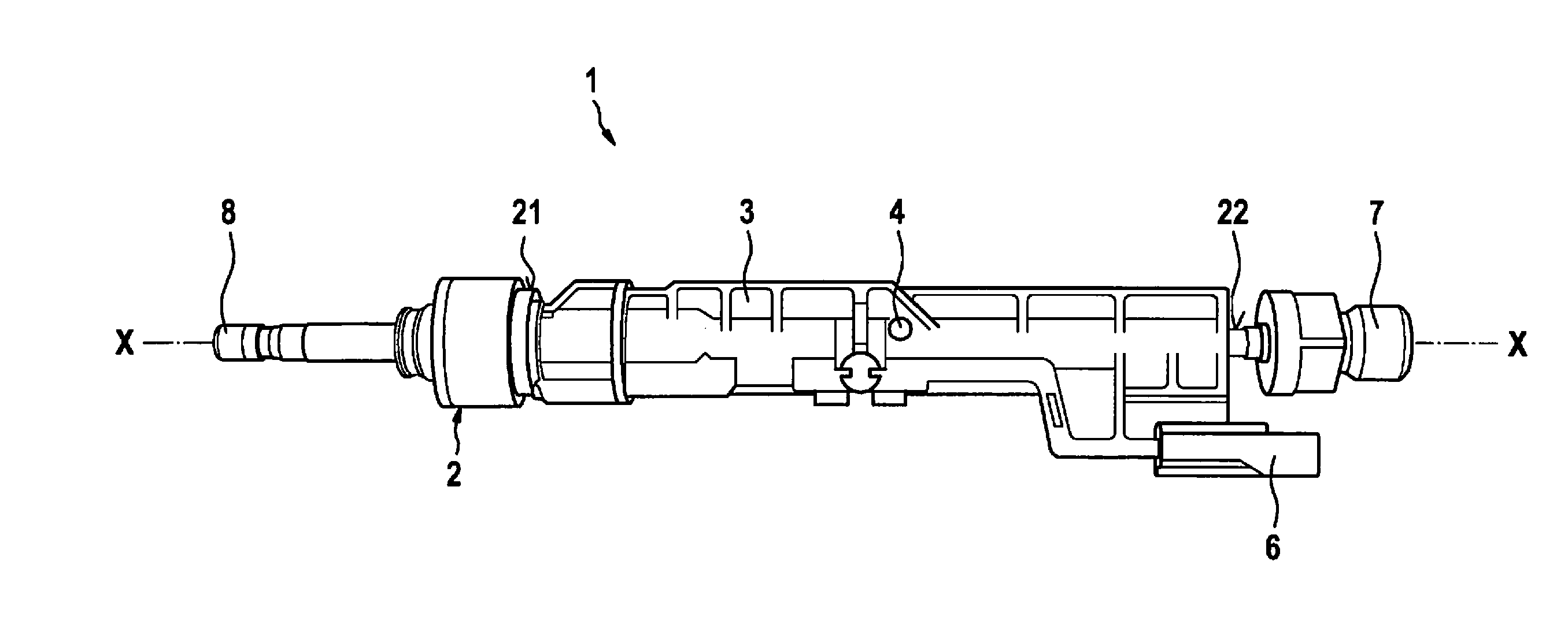
[0025] Example embodiments of the present invention, are directed to an injector 1, an injection-molding tool, and a manufacturing method for the injector. FIG. 1 schematically shows a side view of an example injector 1, which is, for example, a fuel injector for injecting liquid fuel.
[0026] Injector 1 includes a main body 2, which includes a metallic valve housing, in which an actuator, for example, a magnetic actuator, and a closing element, for example, a valve needle or the like, are situated. The injector injects fuel, for example, directly into a combustion chamber at end 8 of the injector opposite to a fuel connection 7.
[0027] In addition to main body 2, injector 1 includes an injection-molded housing 3. Injection-molded housing 3 is preferably manufactured from a plastic material. Injection-molded housing 3 furthermore preferably includes an electrical plug connection 6, via which a power supply and control of injector 1 take place.
[0028] A first opening 4, which is cylindrical in this example embodiment, is provided in injection-molded housing 3. First opening 4 extends completely through injection-molded housing 3 up to the outer jacket of main body 2. As is apparent from FIG. 1, first opening 4 is perpendicular to a center axis X-X of the injector.
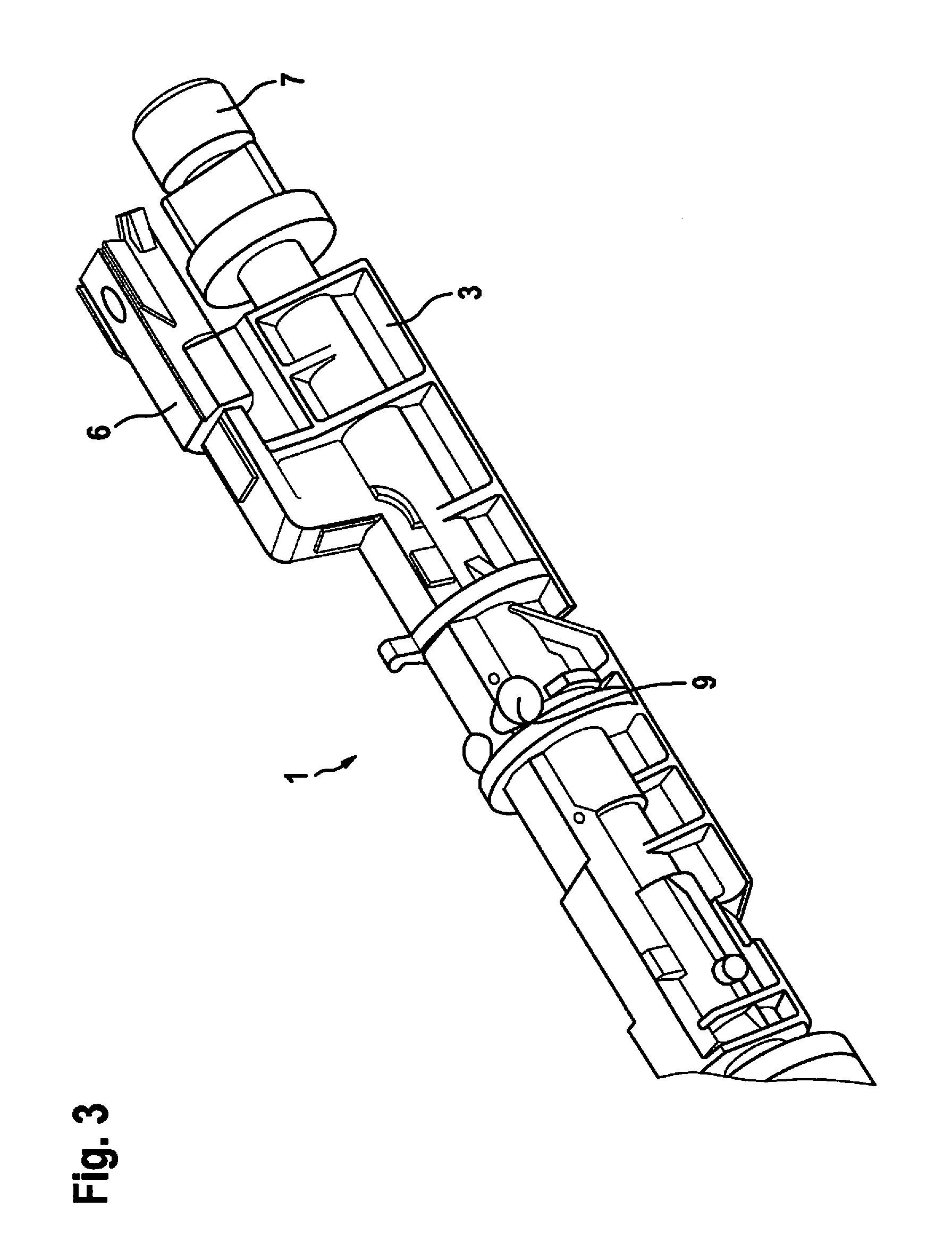
[0029] As is apparent from FIGS. 2 and 3, injection-molded housing 3 completely encloses a middle part of main body 2 in the circumferential direction of the main body.
[0030] Furthermore, a first tool contact surface 21 and a second tool contact surface 22 are provided on main body 2 of the injector. As is apparent from FIG. 1, first and second tool contact surfaces 21, 22 delimit the expansion of injection-molded housing 3 in axial direction X-X. An injection-molding tool 30, which is described hereafter with reference to FIGS. 4 and 5, rests against the two tool contact surfaces.
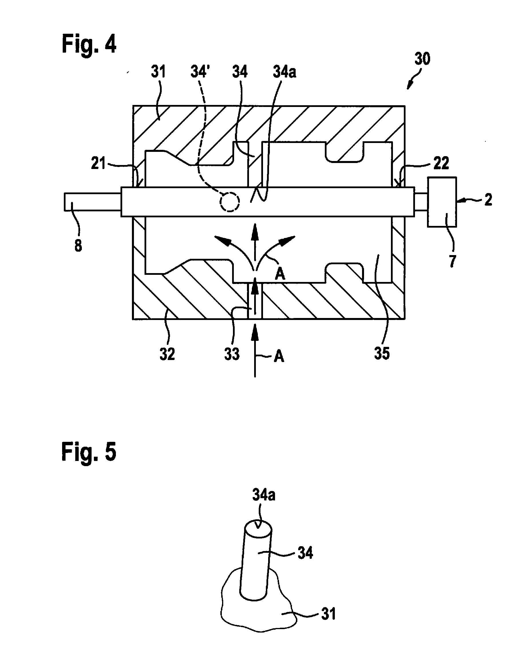
[0031] As is apparent from FIG. 4, injection-molding tool 30 includes a first tool half 31 and a second tool half 32. An inflow opening 33, via which the injection-molding material is injected into a cavity 35, which results upon the assembly of first and second tool half 31, 32, is provided in second tool half 32. This is indicated by arrows A in FIG. 4.
[0032] A cylindrical support pin 34, which protrudes into cavity 35, is provided in first tool half 31. As is apparent from FIG. 4, support pin 34 is used to support main body 2, which is inserted as an insert into injection-molding tool 30, in order to produce injection-molded housing 3 by injection-molding. First and second tool halves 31, 32 form a seal on first and second tool contact surfaces 21, 22, as schematically shown in FIG. 4.
[0033] Main body 2, designed as an insert, includes a cylindrical shape in the area of support pin 34. In this way, a free end 34a, which is a planar surface, rests linearly against main body 2. After the injection molding and removal of the two tool halves 31, 32, first opening 4 shown in FIGS. 1 and 2 is thus formed by support pin 34. Because of the linear contact during the injection-molding procedure between support pin 34 and main body 2, a plastic skin results at the end of first opening 4, which includes a slotted opening in axial direction X-X of main body 2.
[0034] As is apparent from FIG. 4, support pin 4 is used during the injection-molding procedure to support main body 2 against the injection pressure, which arises due to the injection of the injection-molding material into cavity 35. As is furthermore apparent from FIG. 4, support pin 34 is situated directly opposite to inflow opening 33 for this purpose. In this way, an optimal support of the insert can be achieved. A diameter of cylindrical support pin 34 is preferably equal to a diameter of inflow opening 33.
[0035] A gating point 9, which is located on the outer circumference of injection-molded housing 3, is schematically indicated in FIG. 3.
[0036] According to an example embodiment of the present invention, a method for manufacturing injector 1 can therefore be carried out very easily and cost-effectively using injection-molding tool 30, and in particular bending of main body 2 of the injector, which is designed as an insert, can be avoided. The following are three alternatives that are possible for this purpose. On the one hand, as described, support pin 34 can contact main body 2 in injection-molding tool 30, as shown in FIG. 4. According to an alternative, there can also be no contact between support pin 34 and inserted main body 2, but rather a very small distance, preferably less than 0.5 mm, particularly preferably less than or equal to 0.1 mm, so that a minimum deflection of the main body during the injection procedure is enabled. This minimal bending does not damage main body 2, however. As another alternative, a pre-tension and thus a deflection of main body 2 against the injection direction through inflow opening 33 can also be enabled by a contact of support pin 34 with inserted main body 2. This deflection against the injection direction can be compensated for by the high pressure during the injection of the injection-molding material, so that an injector having injection-molded housing 3 can be manufactured, which does not have a deflection on main body 2 as a final product.
[0037] FIG. 6 shows an injector 1 according to another example embodiment of the present invention. Injector 1 of this example embodiment essentially corresponds to the first example embodiment, a second opening 5 also being provided in injection-molded housing 3 in addition to first opening 4 in injection-molded housing 3. As is apparent from FIG. 6, first and second openings 4, 5 are situated at an angle of 90.degree. relative to each other in injection-molded housing 3. A first center axis of first opening 4 is identified with reference numeral M1 in FIG. 6 and a second center axis M2 of second opening 5 is perpendicular thereto. Both center axes M1, M2 are in turn perpendicular relative to center axis X-X of injector 1.
[0038] As is furthermore apparent from FIG. 6, first opening 4 and second opening 5 are situated offset in relation to each other by a distance Y in the direction of center axis X-X of the injector. A gating point 9 is situated between first opening 4 and second opening 5 in axial direction X-X of the injector. As explained in the first example embodiment, first opening 4 and second opening 5 are produced by two support pins, which are provided in the injection-molding tool. An improved support of inserted main body 2 in the injection-molding tool can be achieved by the provision of two support pins, in particular also against a melt pressure that acts on inserted main body 2 during and after the injection procedure. The second support pin is schematically shown by dashed lines with reference numeral 34' in FIG. 4.
* * * * *
D00000
D00001
D00002
D00003
D00004
D00005
XML
uspto.report is an independent third-party trademark research tool that is not affiliated, endorsed, or sponsored by the United States Patent and Trademark Office (USPTO) or any other governmental organization. The information provided by uspto.report is based on publicly available data at the time of writing and is intended for informational purposes only.
While we strive to provide accurate and up-to-date information, we do not guarantee the accuracy, completeness, reliability, or suitability of the information displayed on this site. The use of this site is at your own risk. Any reliance you place on such information is therefore strictly at your own risk.
All official trademark data, including owner information, should be verified by visiting the official USPTO website at www.uspto.gov. This site is not intended to replace professional legal advice and should not be used as a substitute for consulting with a legal professional who is knowledgeable about trademark law.