Ergonomic Handle for an Exercise Machine
Lagree; Sebastien Anthony Louis ; et al.
U.S. patent application number 16/383721 was filed with the patent office on 2019-10-17 for ergonomic handle for an exercise machine. The applicant listed for this patent is Lagree Technologies, Inc.. Invention is credited to Samuel D. Cox, Andy H. Gibbs, John C. Hamilton, Sebastien Anthony Louis Lagree, Todd G. Remund, Max Wunderlich.
| Application Number | 20190314672 16/383721 |
| Document ID | / |
| Family ID | 68161116 |
| Filed Date | 2019-10-17 |


View All Diagrams
| United States Patent Application | 20190314672 |
| Kind Code | A1 |
| Lagree; Sebastien Anthony Louis ; et al. | October 17, 2019 |
Ergonomic Handle for an Exercise Machine
Abstract
An improved ergonomic handle for an exercise machine having a cross-sectional shape designed to more closely conform with the natural anatomical shape of a hand in a grasping position for reducing compressive pressure on the hand during exercise, improving grip, and accommodating a wide range of hand sizes. The ergonomic handle for an exercise machine generally includes solid bars and hollow tubular structures with a variety of substantially polygonal cross-sections, including various substantially triangular and trapezoidal cross-sections. Alternative embodiments include underlying bars and handles of various cross-sectional shapes with resilient cover materials having substantially polygonal cross-sections. The improved ergonomic handles may replace traditional round cross-section handles anywhere on an exercise machine they may be located.
| Inventors: | Lagree; Sebastien Anthony Louis; (Burbank, CA) ; Gibbs; Andy H.; (Tucson, AZ) ; Hamilton; John C.; (Santa Clarita, CA) ; Cox; Samuel D.; (Yuba City, CA) ; Remund; Todd G.; (Yuba City, CA) ; Wunderlich; Max; (Los Angeles, CA) | ||||||||||
| Applicant: |
|
||||||||||
|---|---|---|---|---|---|---|---|---|---|---|---|
| Family ID: | 68161116 | ||||||||||
| Appl. No.: | 16/383721 | ||||||||||
| Filed: | April 15, 2019 |
Related U.S. Patent Documents
| Application Number | Filing Date | Patent Number | ||
|---|---|---|---|---|
| 62658240 | Apr 16, 2018 | |||
| Current U.S. Class: | 1/1 |
| Current CPC Class: | A63B 21/023 20130101; A63B 21/0724 20130101; A63B 71/0054 20130101; A63B 21/0726 20130101; A63B 2071/0063 20130101; A63B 21/4045 20151001; A63B 21/4035 20151001; A63B 21/4031 20151001; A63B 21/0428 20130101; A63B 21/0442 20130101 |
| International Class: | A63B 21/00 20060101 A63B021/00; A63B 21/04 20060101 A63B021/04 |
Claims
1. An exercise machine, comprising: a frame having a first end and a second end; a reciprocating platform movably positioned upon the frame between the first end and the second end; a tension spring connected between the reciprocating platform and the frame that applies a bias force upon the reciprocating platform; and a first platform handle connected to the reciprocating platform, wherein the first platform handle comprises a triangular cross-section.
2. The exercise machine of claim 1, wherein the first platform handle comprises an upper surface, a first side surface, and a second side surface.
3. The exercise machine of claim 2, wherein the upper surface and the first side surface converge at a first vertex, wherein the first side surface and the second side surface converge at a second vertex, and wherein the second side surface and the upper surface converge at a third vertex.
4. The exercise machine of claim 3, wherein the first vertex, the second vertex, and the third vertex each comprise a rounded surface.
5. The exercise machine of claim 1, wherein the first platform handle comprises a Reuleaux triangle cross-section.
6. The exercise machine of claim 1, wherein the first platform handle extends along a first side of the reciprocating platform.
7. The exercise machine of claim 6, comprising a second platform handle connected to the reciprocating platform, wherein the second platform handle comprises a triangular cross-section.
8. The exercise machine of claim 7, wherein the second platform handle extends along a second side of the reciprocating platform.
9. The exercise machine of claim 1, wherein the first platform handle comprises a bar and a padding material surrounding the bar.
10. The exercise machine of claim 9, wherein the padding material comprises a triangular cross-section.
11. The exercise machine of claim 10, wherein the bar comprises a rectangular cross-section.
12. The exercise machine of claim 9, wherein the bar comprises protrusions adapted to engage an inner surface of the padding material.
13. The exercise machine of claim 12, wherein the bar comprises a circular cross-section.
14. An exercise machine, comprising: a frame having a first end and a second end; a reciprocating platform movably positioned upon the frame between the first end and the second end; a tension spring connected between the reciprocating platform and the frame that applies a bias force upon the reciprocating platform; and a first platform handle connected to the reciprocating platform, wherein the first platform handle comprises a trapezoidal cross-section.
15. The exercise machine of claim 14, wherein the first platform handle comprises an upper surface, a first side surface, a second side surface, and a bottom surface.
16. The exercise machine of claim 15, wherein the upper surface and the first side surface of the first platform handle meet at a first vertex, wherein the first side surface and the bottom surface of the first platform handle meet at a second vertex, wherein the bottom surface and the second side surface of the first platform handle meet at a third vertex, and wherein the second side surface and upper surface of the first platform handle meet at a fourth vertex.
17. The exercise machine of claim 14, comprising a second platform handle connected to the reciprocating platform, wherein the second platform handle comprises a trapezoidal cross-section.
18. The exercise machine of claim 17, wherein the first platform handle extends along a first side of the reciprocating platform and wherein the second platform handle extends along a second side of the reciprocating platform.
19. The exercise machine of claim 14, wherein the first platform handle comprises a bar and a padding material surrounding the bar, wherein the padding material comprises a trapezoidal cross-section.
20. The exercise machine of claim 19, wherein the bar comprises protrusions adapted to engage an inner surface of the padding material.
Description
CROSS REFERENCE TO RELATED APPLICATIONS
[0001] I hereby claim benefit under Title 35, United States Code, Section 119(e) of U.S. provisional patent application Ser. No. 65/658,240 filed Apr. 16, 2018. The 65/658,240 application is currently pending. The 65/658,240 application is hereby incorporated by reference into this application.
STATEMENT REGARDING FEDERALLY SPONSORED RESEARCH OR DEVELOPMENT
[0002] Not applicable to this application.
BACKGROUND
Field
[0003] Example embodiments in general relate to the field of exercise machines and exercise equipment. More specifically, example embodiments relate to an ergonomic handle for an exercise machine having a cross-sectional shape designed to more closely conform with the natural anatomical shape of a hand in a grasping position for reducing compressive pressure on the hand during exercise, improving grip, and accommodating a wide range of hand sizes.
Related Art
[0004] Any discussion of the related art throughout the specification should in no way be considered as an admission that such related art is widely known or forms part of common general knowledge in the field.
[0005] Traditional exercise machines have long employed round handles and other round gripping structures. Further, round bars have long been the standard for gripping structures for other exercise equipment such as dumbbells and barbells.
[0006] While round handles and bars serve their intended use as hand-gripping structures adequately, they are intended for very short duration exercise cycles, for instance, less than one minute. However, they do not provide optimized geometry for supporting exercisers to engage for longer periods with exercise equipment, for instance, five minutes or more. Moreover, they do not provide optimal gripping surfaces for a variety of hand sizes and for exercises involving both pushing and pulling forces.
SUMMARY
[0007] An example embodiment is directed to an ergonomic handle for an exercise machine that provides a novel improvement over traditional round handles and bars typically used as the gripping structures on exercise machines and other exercise equipment such as free weights, e.g., dumbbells and barbells. Example embodiments of the ergonomic handle for an exercise machine include an anatomically optimized, substantially polygonal-shaped gripping geometry that provides for improved hand engagement with exercise machines and equipment, and increases hand-to-bar surface area engagement when supporting substantially the weight of an exerciser, thereby reducing compressive pressure on the palm of the hand. The improved bar geometry also better accommodates a larger range of male and female hand sizes when compared to the traditional round bar geometry.
[0008] Example embodiments of ergonomic handles comprise solid bars and hollow tubular structures with a variety of substantially polygonal cross-sections, including various substantially triangular and trapezoidal cross-sections. Alternative embodiments include underlying bars and handles of various cross-sectional shapes with resilient covers having substantially polygonal cross-sections. The improved ergonomic handles preferably replace traditional round cross-section handles anywhere on an exercise machine they may be located.
[0009] There has thus been outlined, rather broadly, some of the embodiments of the ergonomic handle for an exercise machine in order that the detailed description thereof may be better understood, and in order that the present contribution to the art may be better appreciated. There are additional embodiments of the ergonomic handle for an exercise machine that will be described hereinafter and that will form the subject matter of the claims appended hereto. In this respect, before explaining at least one embodiment of the ergonomic handle for an exercise machine in detail, it is to be understood that the ergonomic handle for an exercise machine is not limited in its application to the details of construction or to the arrangements of the components set forth in the following description or illustrated in the drawings. The ergonomic handle for an exercise machine is capable of other embodiments and of being practiced and carried out in various ways. Also, it is to be understood that the phraseology and terminology employed herein are for the purpose of the description and should not be regarded as limiting.
BRIEF DESCRIPTION OF THE DRAWINGS
[0010] Example embodiments will become more fully understood from the detailed description given herein below and the accompanying drawings, wherein like elements are represented by like reference characters, which are given by way of illustration only and thus are not limitative of the example embodiments herein.
[0011] FIG. 1A is a perspective view of an exercise machine with improved ergonomic handles in accordance with an example embodiment.
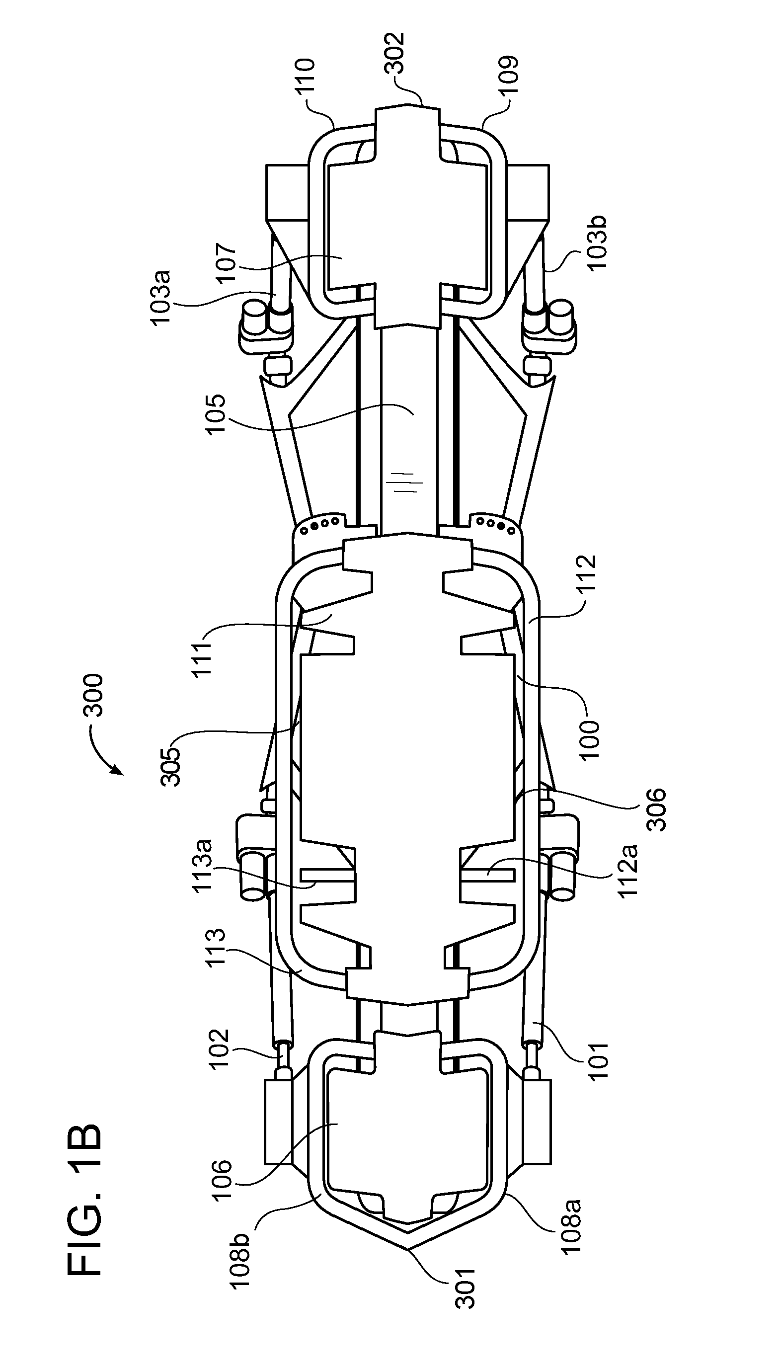
[0012] FIG. 1B is a top plan view of an exercise machine with improved ergonomic handles in accordance with an example embodiment.
[0013] FIG. 2 is a top plan view of an exercise machine with improved ergonomic handles with several components illustrated in outline to reveal internal components.
[0014] FIG. 3A is a perspective view of a section of a prior art handle bar having a substantially round cross-section.
[0015] FIG. 3B is a cross-sectional view of a section of a prior art handle bar having a substantially round cross-section with a resilient cover material.
[0016] FIG. 4A is a side view of a representative human hand and corresponding skeletal structure in a grasping position.
[0017] FIG. 4B is a side view of a representative human hand and corresponding skeletal structure grasping an object with a substantially triangular cross-section.
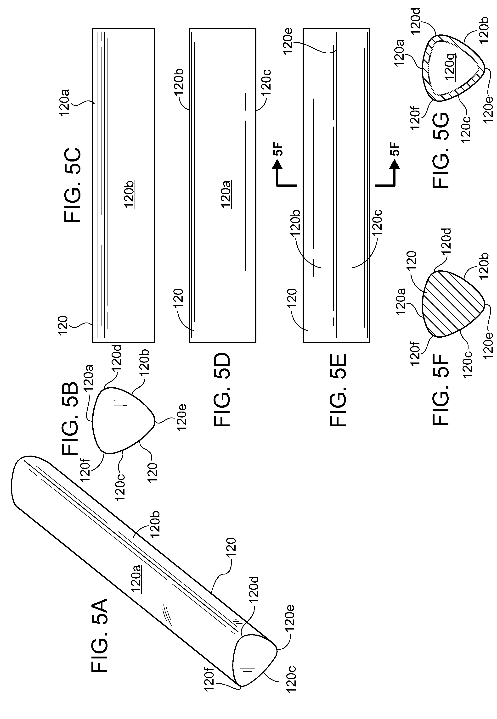
[0018] FIG. 5A is a perspective view of a section of an improved ergonomic handle bar having a substantially triangular cross-section in accordance with an example embodiment.
[0019] FIG. 5B is an end view of a section of an improved ergonomic handle bar having a substantially triangular cross-section in accordance with an example embodiment.
[0020] FIG. 5C is a side view of a section of an improved ergonomic handle bar having a substantially triangular cross-section in accordance with an example embodiment.
[0021] FIG. 5D is a top view of a section of an improved ergonomic handle bar having a substantially triangular cross-section in accordance with an example embodiment.
[0022] FIG. 5E is a bottom view of a section of an improved ergonomic handle bar having a substantially triangular cross-section in accordance with an example embodiment.
[0023] FIG. 5F is a cross-sectional view of a section of an improved solid ergonomic handle bar having a substantially triangular cross-section in accordance with an example embodiment.
[0024] FIG. 5G is a cross-sectional view of a section of an improved hollow ergonomic handle bar having a substantially triangular cross-section in accordance with an example embodiment.
[0025] FIG. 6A is a perspective view of a section of an improved ergonomic handle comprising a hollow bar having a substantially triangular cross-section embodiment with a preferably resilient cover material in accordance with an example embodiment.
[0026] FIG. 6B is an an end view of a section of an improved ergonomic handle comprising a hollow bar having a substantially triangular cross-section with a preferably resilient cover material in accordance with an example embodiment.
[0027] FIG. 6C is a side view of a section of an improved ergonomic handle comprising a hollow bar having a substantially triangular cross-section with a preferably resilient cover material in accordance with an example embodiment.
[0028] FIG. 6D is a top view of a section of an improved ergonomic handle comprising a hollow bar having a substantially triangular cross-section with a preferably resilient cover material in accordance with an example embodiment.
[0029] FIG. 6E is a bottom view of a section of an improved ergonomic handle comprising a hollow bar having a substantially triangular cross-section with a preferably resilient cover material in accordance with an example embodiment.
[0030] FIG. 6F is a cross-sectional view of a section of an improved ergonomic handle comprising a hollow bar having a substantially triangular cross-section with a preferably resilient cover material having a substantially triangular cross-section in accordance with an example embodiment.
[0031] FIG. 6G is a cross-sectional view of a section of an improved ergonomic handle comprising a hollow bar having a substantially rectangular cross-section with a preferably resilient cover material having a substantially triangular cross-section in accordance with an example embodiment.
[0032] FIG. 6H is a cross-sectional view of a section of an improved ergonomic handle comprising a hollow bar having a substantially round cross-section with circumferential protrusions and a preferably resilient cover material having a substantially triangular cross-section in accordance with an example embodiment.
[0033] FIG. 7A is a side view of a representative hand grasping a traditional handle comprising a substantially cylindrical tube structure.
[0034] FIG. 7B is a side view of a representative hand grasping an improved ergonomic handle comprising a substantially triangular tube structure in accordance with an example embodiment.
[0035] FIG. 7C is a side view showing the geometry of the space formed between the index finger tip and end of the thumb of the skeletal structure of a representative hand in accordance with an example embodiment.
[0036] FIG. 7D is a side view of a representative hand grasping an improved ergonomic handle comprising a tube structure having a substantially trapezoidal cross-section in accordance with an example embodiment.
[0037] FIG. 7E is a side view of a representative relatively small hand grasping an improved ergonomic handle comprising a tube structure having another substantially trapezoidal cross-section in accordance with an example embodiment.
[0038] FIG. 7F is a side view of a representative relatively large hand grasping an improved ergonomic handle comprising a tube structure having another substantially trapezoidal cross-section in accordance with an example embodiment.
[0039] FIG. 8A is a cross-sectional view taken along section line S1-S1 in FIG. 1 of a reciprocating platform of an exercise machine with improved ergonomic handles comprising a substantially triangular cross section in accordance with an example embodiment.
[0040] FIG. 8B is a cross-sectional view of a reciprocating platform of an exercise machine with improved ergonomic handles comprising one substantially trapezoidal cross-section as illustrated in FIG. 7D in accordance with an example embodiment.
[0041] FIG. 8C is a cross-sectional view of a reciprocating platform of an exercise machine with improved ergonomic handles comprising another substantially trapezoidal cross-section as illustrated in FIGS. 7E and 7F in accordance with an example embodiment.
DETAILED DESCRIPTION
[0042] Various aspects of specific embodiments are disclosed in the following description and related drawings. Alternate embodiments may be devised without departing from the spirit or the scope of the present disclosure. Additionally, well-known elements of exemplary embodiments will not be described in detail or will be omitted so as not to obscure relevant details. Further, to facilitate an understanding of the description, a discussion of several terms used herein follows.
[0043] The word "exemplary" is used herein to mean "serving as an example, instance, or illustration." Any embodiment described herein as "exemplary" is not necessarily to be construed as preferred or advantageous over other embodiments. Likewise, the term "embodiments" is not exhaustive and does not require that all embodiments include the discussed feature, advantage or mode of operation.
[0044] The terms "bar" and "handle" are used herein to mean a structural member of an exercise machine or exercise equipment that is typically gripped or grasped by a hand of an exerciser during exercise. As used herein, a "bar" or "handle" may be constructed of a solid material, a substantially tubular structure such as a hollow pipe of a round, triangular, rectangular, or other polygonal cross-sectional shape, or an assembly of a substantially solid or hollow structure covered with a substantially resilient material. Therefore, the terms "bar" and "handle" are not meant to be limiting, and are used to describe any handle-like structure intended to be gripped or grasped by a user during exercise.
[0045] Although more than one embodiment is illustrated and described herein, it will be appreciated by those of ordinary skill in the art that a wide variety of alternate and/or equivalent implementations may be substituted for the specific embodiments shown and described without departing from the scope of the present disclosure. This application is intended to cover any adaptations or variations of the embodiments discussed herein.
A. Overview.
[0046] An example embodiment may comprise a frame or base support structure 100 having a first end 301 and a second end 302 and a reciprocating platform 111 movably positioned upon the frame or base support structure 100 between the first end 301 and the second end 302. A tension spring 318 is connected between the reciprocating platform 111 and the frame or base support structure 100 that applies a bias force upon the reciprocating platform 111. A first platform handle 118, 120 is connected to the reciprocating platform 111, wherein the first platform handle 118, 120 comprises a triangular cross-section. The first platform handle 118, 120 may comprise an upper surface 120a, a first side surface 120b, and a second side surface 120c. The upper surface 120a and the first side surface 120b converge at a first vertex 120d, the first side surface 120b and the second side surface 120c converge at a second vortex 120e, and the second side surface 120c and the upper surface 120a converge at a third vertex 120f. The first vertex 120d, the second vertex 120e, and the third vertex 120f may each comprise a rounded surface. The first platform handle 118, 120 may comprise a Reuleaux triangle cross-section wherein the upper surface 120a and side surfaces 120b, 120c are bowed outwardly.
[0047] The first platform handle 118, 120 may extend along a first side 305 of the reciprocating platform 111. A second platform handle 119, 120 may be connected to the reciprocating platform 111, wherein the second platform handle 119, 120 comprises a triangular cross-section. The second platform handle 119, 120 may extend along a second side 306 of the reciprocating platform 111.
[0048] The first platform handle 118, 120 may comprise a bar 123 and a padding material 122 surrounding the bar 123. The padding material 122 may comprise a triangular cross-section. The bar 123 may comprise a rectangular cross-section. The bar 123 may comprise protrusions 123k adapted to engage an inner surface of the padding material 122. The bar 123 may comprise a circular cross-section.
[0049] Another exemplary embodiment may comprise a frame or base support structure 100 having a first end 301 and a second end 302, a reciprocating platform 111 movably positioned upon the frame or base support structure 100 between the first end 301 and the second end 302, and a tension spring 318 connected between the reciprocating platform 111 and the frame or base support structure 100 that applies a bias force upon the reciprocating platform 111. A first platform handle 118, 128, 130 is connected to the reciprocating platform 111, wherein the first platform handle 118, 128, 130 comprises a trapezoidal cross-section.
[0050] The first platform handle 118, 128, 130 may comprise an upper surface 128a, 130a, a first side surface 128b, 130b, a second side surface 128c, 130c, and a bottom surface 128d, 130d. The upper surface 128a, 130a and the first side surface 128b, 130b of the first platform handle 118, 128, 130 meet at a first vertex 128e, 130e, the first side surface 128b, 130b and the bottom surface 128d, 130d of the first platform handle 118, 128, 130 meet at a second vertex 128f, 130f, the bottom surface 128d, 130d and the second side surface 128c, 130c of the first platform handle 118, 128, 130 meet at a third vertex 128g, 130g, and the second side surface 128c, 130c and upper surface 120a, 130a of the first platform handle 118, 128, 130 meet at a fourth vertex 128h, 130h.
[0051] A second platform handle 119, 128, 130 may be connected to the reciprocating platform 111, wherein the second platform handle 119, 128, 130 comprises a trapezoidal shape. The first platform handle 118, 128, 130 may extend along a first side 305 of the reciprocating platform 111 and the second platform handle 119, 128, 130 may extend along a second side 306 of the reciprocating platform 111. The first platform handle 119, 128, 130 may comprise a bar 123 and padding material 122 around the bar 123, with the padding material 122 comprising a trapezoidal cross-section. The bar 123 may comprise protrusions 123k adapted to engage an inner surface of the padding material 122.
[0052] An example improved ergonomic handle 120, 128, 130 for an exercise machine 300 generally comprises a substantially polygonal-shaped gripping geometry optimized to conform closely to the natural anatomical shape of a partially closed hand when in position to grip or grasp the handle. The ergonomic handle 120, 130 provides for improved hand engagement with exercise machines 300 and equipment, increases hand-to-bar surface area engagement when supporting substantially the weight of an exerciser 210, and thereby reduces the compressive pressure on the palm of the hand. The improved handle or bar geometry also better accommodates a larger range of male and female hand sizes when compared to a traditional round handle or bar geometry.
[0053] Example embodiments of improved ergonomic handles 120, 130 comprise solid bars and hollow tubular structures with a variety of substantially polygonal cross-sections, including various substantially triangular and trapezoidal cross-sections. Alternative embodiments include underlying bars and handles of various cross-sectional shapes with resilient cover materials having substantially polygonal cross-sections. The improved ergonomic handles preferably replace traditional round cross-section handles anywhere on an exercise machine they may be located.
B. Exercise Machine with Improved Ergonomic Handles.
[0054] FIGS. 1A, 1B, and 2 are perspective and top views respectively of an exercise machine 300 with a plurality of improved ergonomic handles 120, 130 adapted to be grasped by an exerciser while performing exercises. The exercise machine 300 may comprise a resistance training machine which is comprised of a frame or base support structure 100 to which the proximal ends of a front left actuator 101, front right actuator 102, back left actuator 103b, and back right actuator 103a are movably affixed.
[0055] The distal ends of the actuators 101, 102, 103a, 103b just described are movably affixed to an upper machine structure comprising a longitudinal center beam assembly 105 extending substantially the length of the machine 300, a fixed front platform 106, a fixed back platform 107, and a reciprocating platform 111. The reciprocating platform 111 may be movably affixed to the center beam assembly by means of trolley wheels 116, 117 (see FIGS. 8A-8C) that engage parallel guide rails 104 positioned on opposed sides of the center beam assembly 105. The reciprocating platform 111 therefore is movable linearly parallel to and substantially the length of the center beam assembly between the front platform 106 and back platform 107.
[0056] In practice, an exerciser 210 positions a part of the exerciser's body on one or more of the platforms 106, 107 just described, and pushes or pulls the reciprocating platform 111 linearly between the front and back stationary platforms 106, 107 against a variable resistance biasing force induced upon the reciprocating platform 111. The variable resistance biasing force may be provided by a plurality of tensioning springs 318. The tensioning springs 318 may be connected between the frame or base support structure 100 and a pulley cassette structure 308 by a plurality of looped cables 315 and cable connectors 316. The pulley cassette 308 is in turn connected to the reciprocating platform 111. The cables 315 may extend through the longitudinal center beam assembly 105 and the ends of the cables 315 proximate to the pulley cassette 308 may have tension knobs 303, 304 that are releasably engageable in slots on the front and back ends of the pulley cassette 308.
[0057] One or more tensioning springs 318 thus may be selectively connected to the front and back of the pulley cassette 308 to selectively provide resistance in forward and reverse directions of motion of the reciprocating platform 111. A similarly improved exercise machine 300 is shown and described in published U.S. Patent Application No. US 2018/0021621 A1, which names the inventors named herein and is assigned to the assignee of this application. That application is incorporated herein by reference.
[0058] As may be appreciated, while performing any of a vast number of exercises upon such an exercise machine 300, exercisers 210 may grasp one or more of a plurality of handles 108a, 108b, 109, 110, 112, 113 including a front right platform handle 108b, a front left platform handle 108a, a back left platform handle 109, a back right platform handle 110, a left reciprocating platform handle 112, and/or a right reciprocating platform handle 113. Additional handles 112a, 113a may also be provided in cut-outs in the reciprocating platform 111.
[0059] Traditionally, tubes or bars with substantially round cross-sections have been used as handles or gripping structures for exercise equipment such as dumbbells and barbells, and the cylindrical geometry of such gripping structures similarly has been adapted for handles on stationary exercise machines. In contrast, the exercise machine shown in FIGS. 1A, 1B, and 2 has the traditional handle structures replaced with improved ergonomic handles 120 having substantially triangular cross-sections. As will be seen herein, improved ergonomic handles 120, 130 may also have a variety of other substantially polygonal cross-sectional shapes.
[0060] FIG. 3A is a perspective view of a section of a bar 121 having a round cross-section. The drawing is presented as a reference to show a section of a traditional prior art round handle that would typically be found on stationary exercise machines and exercise equipment such as free weights. However, as explained below, the traditional cylindrical handle does not conform well to the natural anatomy of a typical hand in a gripping or grasping position. As described below, a typical hand in a gripping or grasping position more closely defines a substantially polygonal structure, opening, and space.
[0061] FIG. 3B is cross-sectional view of a traditional prior art handle bar 121 or other structural member 125 having a round cross-section with a resilient material 124 also having a substantially round cross-section applied over the bar to provide a gripping and/or cushioning surface. As used on exercise equipment, the orientation of a cylindrical bar 121 with respect to its central longitudinal axis is not important since any exerciser 210 or exercise equipment rotation about the central axis of the cylindrical bar 121 will result in the same contact surface between the bar 121 and the exerciser's 210 hand 209 209. Therefore, when the resilient padding material 124 is applied over a round or cylindrical structural member 125, rotation of the resilient material about the central axis of the structural member is of no consequence since the geometry and orientation of the round exterior surface of the resilient material remains effectively unchanged.
[0062] Accordingly, one advantage of using traditional prior art cylindrical handles with substantially round cross-sections is that the geometry does not require any specific orientation with respect to the machine or equipment, thus allowing an exerciser to grab the handle portion without regard to the orientation of the equipment. However, a significant disadvantage of traditional prior art handle bars 121 with round cross-sections is that a round handle geometry is not the optimum geometry for the natural anatomy of the typical human hand 209. Prolonged use of traditional round bars 121 or handles during exercise can result in various injuries to the hand caused by the concentration and increase of forces applied to the hand over a small bar-to-hand contact surface area. Therefore, a non-round geometry is preferable to a round geometry for an exercise machine handle in order to increase the handle to hand surface area and correspondingly to spread and reduce the concentration of compressive force loading against an exerciser's 210 hands 209.
C. Improved Ergonomic Handles with Substantially Triangular Cross-Sections.
[0063] FIG. 4A is a side view of a representative human hand 209 and corresponding skeletal structure in a typical gripping or grasping position. As will be readily appreciated by those skilled in the art, the geometry of the fingers and opposed thumb do not form a substantially round structure, substantially round opening, or substantially round enclosed space when the fingers and thumb are partially closed, such as in the position assumed when gripping or grasping a handle. More specifically, the carpal and metacarpal bones of the hand 209 are substantially longitudinal bones that articulate relative to the connected bones about a joint. When the fingers and thumb of a typical hand 209 are partially closed and positioned for grasping an object, the resulting structure of the hand 209, the opening defined between the fingers and thumb, and the open space enclosed by the partially closed hand 209 comprise more of a polygonal shape substantially perpendicular to the axis of the lower arm. Moreover, the vertices of the polygonal shape are somewhat rounded.
[0064] In the drawing, a representative lower arm 200 of an exerciser is shown comprising the radius and ulna bones 201 with the distal ends terminating at the carpal bones 202 of the wrist. The bones of the arm, wrist and hand 209 are shown as dashed lines to differentiate the bony structure from the outer skin of the lower arm and hand.
[0065] The bones comprising the "palm" of the hand 209 are known as metacarpal bones 203 that are substantially straight bones extending between the carpal bones 202 of the wrist at the proximal ends, to the distal "knuckles", or more commonly known as the metacarpal/phalanges joint, or "MCP" joints 204 that connect each metacarpal to the corresponding substantially linear proximal phalange bone 205. The remainder of each finger comprises the proximal phalange connected to a medial phalange 206 by means of an interphalangeal joint, or "IP joint" 208, the medial phalange further connected to the distal phalange 207 by yet another IP joint 208. Dotted line A shows the approximate longitudinal direction of the proximal phalange bone 205 between joints, dotted line B shows the approximate longitudinal direction of the metacarpal bones 203 between joints, and dotted line C shows the approximate longitudinal direction of the distal phalange 207, all when the hand 209 is partially closed in a grasping position. As illustrated, the substantially straight bones of the hands 209 do not naturally define a structure, opening or space that is substantially round in cross-section. Therefore, the typical hand 209 partially closed in a gripping position does not approximate or conform particularly closely or well to a gripping structure having a round geometry. Rather, the structure, opening and enclosed space defined by a typical hand 209 partially closed in a gripping position more closely resemble a substantially polygonal-shaped cross-section.
[0066] FIG. 4B is a side view of a representative hand 209 and corresponding skeletal structure grasping a substantially triangular object. As just described, the bones of the hand are comprised of substantially linear, not arcuate structures that are unable to naturally conform to a cylinder. More specifically, the metacarpal 203, proximal phalanges 205, medial phalanges 206, and distal phalanges 207 at best form a substantially polygonal space in the palm of the hand when the arm flexors are actuated to grip an object. In the drawing, an end view of an improved ergonomic handle bar 120 with a substantially triangular cross-section is shown overlaid into the void or space created when the fingers and thumb are flexed. The handle bar 120 comprises an upper surface 120a, a first side surface 120b and a second side surface 120c. The upper surface 120a and first side surface 120b meet at a first vertex 120d, the first and second side surfaces 120b, 120c meet at a second vertex 120e, and the second side surface 120c and upper surface 120a meet at a third vertex 120f.
[0067] As can be readily seen, the substantially triangularly-shaped bar 120 more closely conforms to the natural relatively straight geometry of the metacarpal 203 and phalanges 205, 206, 207 of the hand 209 when the hand 209 is flexed to grip an object than the circumferential surface of a cylinder. Because of the natural contours of the hand, the substantially-triangularly-shaped bar 120 conforms even more closely to the hand 209 when the straight sides or surfaces 120a, 120b, and 120c of the triangle are subtly curved and the vertices 120d, 120e, and 120f of the triangle are somewhat rounded rather than pointed.
[0068] FIGS. 5A-5F are various views of an improved grasping structure comprising the ergonomic handle or bar 120 having a substantially triangular cross-section. As described previously, the improved handle or bar 120 comprises an upper surface 120a, a first side surface 120b and a second side surface 120c. The upper surface 120a and first side surface 120b meet at a first vertex 120d, the first and second side surfaces 120b, 120c meet at a second vertex 120e, and the second side surface 120c and upper surface 120a meet at a third vertex 120f. Regardless of whether the top leg or surface 120a of the substantially triangular cross-section handle 120 is substantially planar or is subtly curved, it provides a larger and flatter surface area on the handle 120 for an exerciser's 210 hand 209 to engage than the relatively small surface area that is tangent to the top of a traditional cylindrical bar 121 as shown in FIGS. 3A-3B. This constitutes a valuable improvement in exercise machine and exercise equipment handles for supporting the substantial weight of an exerciser 210 as well as additional pushing and pulling force applied by an exerciser 210 while performing various exercises as described in further detail below. Further, the lower legs or surfaces 120c and 120d of the substantially triangular cross-section handle 120 conform more closely than a traditional cylindrical bar 121 to the natural anatomy of a typical hand 209 by more closely conforming to the substantially straight phalange bones 205, 206, 207 when the fingers and thumb are flexed to grasp a handle bar, thus providing significant improvement in both grip and comfort. As mentioned above, with the lower legs or surfaces 120a, 120b, 120c subtly curved and the vertices 120d, 120e, 120f somewhat rounded, the substantially triangular cross-section handle bar 120 conforms even more closely to a typical partially-closed hand 209 in a gripping position.
[0069] FIG. 5G is a cross-sectional view of a variation of the improved ergonomic handle bar shown in FIGS. 5A-5F. As shown in FIG. 5G, the bar 120 may have a hollow interior 120g as an alternative to the solid structure shown in FIGS. 5A-5F.
[0070] It is noted that while the substantially triangular cross-section of the bar 120 shown in FIGS. 5A-5G is similar to a Reuleaux triangle, the cross-section is not intended to be limited to that particular geometry. Rather, variations consistent with achieving the functions and purposes described herein are intended to be encompassed. For example, as illustrated the legs 120a, 120b, 120c of the triangle are preferably subtly rounded like a Reuleaux triangle, but it is contemplated that the legs also may be substantially straight or planar. Also as illustrated, the vertices 120d, 120e, 120f of the triangle are preferably rounded but it is also contemplated that they may be more pointed. The triangle may be equilateral but need not be. The triangle may or may not have any interior right angles and interior angles may or may not be equal. Still further, while the top leg 120a of the triangle is illustrated as being essentially horizontal, depending on the application the entire triangle may be rotated. Alternatively, just the top surface 120a may be slanted from horizontal. Similar variations are intended to be encompassed regarding the other legs of the triangle.
[0071] FIGS. 6A-6F are various views of an alternative improved grasping structure comprising an ergonomic hollow handle bar 123 having a substantially triangular cross-section with a preferably resilient material 122 applied over the bar 123 to provide a gripping and/or cushioning surface. As illustrated, the resilient material 122 preferably has essentially the same substantially triangular cross-sectional shape as the underlying bar 123 to provide the same improved hand-conforming characteristics as described above with respect to the improved handle bar 120. Thus, the resilient material 122 preferably comprises an upper surface 122a, a first side surface 122b and a second side surface 122c. The upper surface 122a and first side surface 122b meet at a first vertex 122d, the first and second side surfaces 122b, 122c meet at a second vertex 122e, and the second side surface 122c and top surface 122a meet at a third vertex 122f.
[0072] Since orientation of the substantially flat surfaces of the triangular handle bar 123 relative to the position of the exerciser may be important, it may be desirable that the resilient triangular padding 122 remain in a fixed position. Therefore, it is preferable that the triangular padding 122 is applied over or affixed to the underlying bar 123 or other non-cylindrical structural member in a manner that prevents rotation of the resilient padding 122 relative to the central axis of the structural member (bar) 123. In FIGS. 6A-6F, the structural member (bar) 123 has a substantially triangular cross-section which relatively pointed vertices 123a, 123b, and 123c, which provide one means to prevent rotation of the resilient padding 122 about the central axis of the structural member (bar) 123. However, other polygonal geometries with protrusions similar to the vertices 123a, 123b, 123c may be used for the structural member (bar) 123 with the same effect. For example, as shown in FIG. 6G, the underlying handle bar or structural member 123 may have a substantially rectangular cross-section with four relatively pointed corners 123g, 123h, 123i, and 123j.
[0073] It is also noted that while the underlying handle bar 123 is illustrated as being hollow, it may be constructed as a solid structure. Further, while the resilient material 122 is illustrated as having a substantially triangular cross-section and orientation similar to the cross-section and orientation of the bar 120 of FIGS. 5A-5G, the cross-section and orientation of the resilient material 122 may be varied in the same manner as described above with respect to the bar 123 consistent with achieving the functions and purposes described herein and such variations are intended to be encompassed. For example, the resilient material 122 may assume a variety of triangular and other substantially polygonal cross-sectional shapes.
[0074] Still further, as shown in FIG. 6H, other means of preventing rotation of the resilient padding 122 about the central axis of the structural member (bar) 123 may be used with the same effect even when using a cylindrical structural member 123. For example, the resilient padding 122 may be affixed to the structural member 123 by means of adhesives or mechanical fasteners, such as protrusions 123k formed circumferentially about the outer surface of the structural member 123 that engage the inner surface of the resilient padding 122.
[0075] It should be appreciated that the resilient padding 122 may also be utilized with the trapezoidal-shaped handle 128, 130 such as the handles 128, 130 shown in FIGS. 7D, 7E, 7F, 8B, and 8C. In such embodiments, the resilient padding 122 may similarly be positioned or connected around an inner bar 123. The resilient padding 122 in such an embodiment may comprise a trapezoidal cross-section. The underlying bar 123 may comprise different shapes and, in some embodiments, may comprise protrusions 123k adapted to engage with an inner surface of the resilient padding 122.
[0076] FIGS. 7A and 7B further illustrate some of the beneficial characteristics of the improved handle structures described herein. FIG. 7A is a side view of a representative hand grasping a traditional substantially cylindrical gripping structure 121. More specifically, a typical hand 209 of an exerciser is shown gripping a round bar 121 during an exercise. In the drawing, a portion of the exerciser's 210 weight is supported by the exerciser's 210 hand 209 209, and correspondingly by the round handle 121. The downward force of the exerciser's 210 weight is expressed as a load L that is exerted against the upper surface 126 of the round handle 121.
[0077] More specifically, since the hand to handle 121 contact surface area supporting the load is limited to the small area of the handle 121 substantially tangential to the upper portion of the arc of the handle 121, the load is expressed by the formula L/X where "L" is the total downward force represented by the four arrows, and "X" is the limited contact area on the handle 121 that substantially normal to the load vector. It will be appreciated that if the contact surface area between the palm of the exerciser's 210 hand 209 and the handle 121 were increased, the distribution of the exerciser's 210 weight against the handle 121 over the greater contact surface area would result in decreased point loading on the exerciser's 210 hand 209, and therefore increased comfort, thus allowing the exerciser 210 to remain comfortably engaged with the handle 121 for a longer period of time during longer exercises. It will also be appreciated that because of the substantially round cross-section of the handle 121, there is less surface area and fewer surfaces and/or protrusions available for the exerciser's 210 hand 209 to engage while applying pushing and pulling force to the handle 121 during exercises, thus limiting the exerciser's 210 grip on the handle 121 during exercises.
[0078] FIG. 7B is an exemplary diagram showing a side view of a representative hand grasping an improved gripping structure having a substantially triangular cross-section. More specifically, a typical hand 209 of an exerciser is shown gripping the improved ergonomic handle bar 120 having a substantially triangular cross-section as illustrated in FIGS. 5A-5G. In the drawing, a portion of the exerciser's 210 weight is supported by the exerciser's 210 hand 209, and correspondingly by the handle 120. The downward force of the exerciser's 210 weight is expressed as a load L that is exerted against the top leg or surface 120a of the triangular cross-section, and therefore the upper load bearing surface 127 of the handle 120.
[0079] Compared to the small hand to handle contact surface area just described in connection with FIG. 7A, the hand to handle contact surface area supporting the load and the weight bearing surface area of the portion of the handle 120 engaged with the exerciser's 210 hand 209 are increased, the load now being expressed by the formula L/(X+Y) where "L" is the total downward force represented by the six arrows, "X" is the limited contact area on the handle 120 that would otherwise be provided by a traditional round handle bar 121, and "Y" is the increased contact area provided by the expanded top surface 120a of the improved triangular cross-section handle 120 as represented by the extended length arrows.
[0080] It can be readily seen that the increased surface area of the top surface 120a of the improved triangular cross-section bar 120 therefore reduces the point-loading and the corresponding compressive forces applied against the exerciser's 210 hand 209, thus allowing the exerciser 210 to engage with the improved handle bar 120 for extended periods of time with significantly increased comfort. This is because the improved geometry of the triangular cross-section handle 120 more closely conforms with the natural anatomy of the typical exerciser's 210 hand 209 when in a partially closed position to grasp a handle 120 of an exercise machine 300 as described herein while performing exercises.
[0081] In addition, it is apparent that the vertices 120d and 120f between the top surface 120a and side surfaces 120b and 120c of the triangle, and the bottom vertex 120e between the two side surfaces 120b and 120c of the triangle provide gripping points or protrusions which improve an exerciser's 210 grip on the handle 120. This is especially beneficial during exercises involving the exerciser 210 applying pushing and pulling forces on the handle 120. Preferably the gripping points or protrusions are located at or near one or more of the joints 204, 208 of the fingers and thumb of the hand 209, thereby providing even more comfort and more improved grip for the exerciser 210.
[0082] It is noted that while the example embodiments described above comprise handle bars 120 with substantially triangular cross-sections, other configurations with other substantially polygonal cross-sectional configurations may also be used consistent with achieving the functions and purposes described herein. Several example embodiments are described below.
D. Improved Ergonomic Handles with Other Substantially Polygonal Cross-Sections.
[0083] FIG. 7C is a side view showing the geometry of the space formed between the index finger tip and end of the thumb of a representative skeletal structure of a typical hand 209 being partially closed in a typical gripping motion. More specifically, as previously described, the arm flexors (not shown) cause the distal phalanges 207 and thumb 211 to approach one another during a grasping motion. Since the distal phalanges 207, medial phalanges 206, proximal phalanges 205, and metacarpals 203 are substantially straight members of the hand 209 articulable about the connecting joints 208, the shape of the interior, grasping portion of the hand 209 forms a substantially polygonal geometry shown in the drawing as a heavy line comprising a substantially trapezoidal-shaped handle 128. As readily seen, the substantially trapezoidal shape of the handle 128 conforms very positively and closely to the geometry of the anterior portion of the hand in the gripping position.
[0084] FIG. 7D is an exemplary diagram showing a side view of a representative hand 209 grasping an improved ergonomic handle 128 with a substantially trapezoidal cross-section. The handle preferably comprises an upper surface 128a, a first side surface 128b, a second side surface 128d, and a bottom surface 128c. The upper surface and first side surface meet at a first vertex 128e, the first side surface and bottom surface meet at a second vertex 128f, the bottom surface and second side surface meet at a third vertex 128g, and the second side surface and top surface meet at a fourth vertex 128h. As previously described, in practice, the compressive force that an exerciser applies to a handle is transferred through the lower arm 200 to the hand, and ultimately to the handle to which the hand is in compressive communication. In the drawing, the plane of the top surface 128a of the substantially trapezoidal cross-section handle 128 is preferably aligned with the plane of the metacarpal bones 203, providing for the largest load supporting surface 129 substantially in engagement with the hand 209 as a means to distribute the load force over the largest possible area of the palm of the hand 209. In the drawing, the outline of a traditional round handle 121 is shown as an overlaid dotted line for comparison.
[0085] As can be readily seen, the area of the upper load bearing surface of the improved substantially trapezoidal cross-section handle 128, indicated by the plurality of arrows, is substantially greater than the area of the load bearing surface of the traditional round cross-section handle bar 121. Further, the surfaces 128b, 128c, and 128d of the substantially trapezoidal cross-section handle being in close communication with the phalanges 205, 206, 207 provide for greater surface contact between the hand 209 and handle 128 as may be preferred when the exerciser 210 is performing exercises that require pulling against the handle 128, opposing the pulling force in the direction as indicated by the dotted arrows. Still further, the vertices 128e, 128f, 128g between the adjacent legs or surfaces 128a, 128b, 128c, 128d of the trapezoid, which preferably are located at or near one or more of the joints 204, 208 of the fingers and thumb of the hand 209, provide an exerciser 210 with additional gripping points or protrusions thus improving the exerciser's 210 grip on the bar 128 during exercise as compared with the traditional round cross-section bar 121.
[0086] FIGS. 7E and 7F are side views of two representative hands 209 of different sizes grasping an improved ergonomic handle 130 having an alternative substantially trapezoidal cross-section. Similar to the improved handle of FIG. 7D, the handle 130 preferably comprises an upper surface 130a, a first side surface 130b, a bottom surface 130c, and a second side surface 130d. The upper surface 130a and first side surface 130b meet at a first vertex 130e, the first side surface 130b and bottom surface 130c meet at a second vertex 130f, the bottom surface 130c and second side surface 130b meet at a third vertex 130g, and the second side surface 130b and top surface 130a meet at a fourth vertex 130h.
[0087] The plane of the top surface 130a of the substantially trapezoidal cross-section handle 130 is preferably aligned with the plane of the metacarpal bones 203, providing for the largest load supporting surface 131 as a means to distribute the load force over the largest possible area of the palm of the hand 209. The area of the upper load bearing surface 131 of the substantially trapezoidal cross-section handle 130, indicated by the plurality of arrows, is substantially greater than the area of the load bearing surface of the traditional round cross-section handle bar 121. Further, the portions of the substantially trapezoidal cross-section handle 130 in close communication with the phalanges 205, 206, 207 provide for greater surface contact between the hand 209 and handle 130 as may be preferred when the exerciser 210 is performing exercises that require pulling against the handle 130, opposing the pulling force in the direction as indicated by the dotted arrows. Still further, the vertices 130e, 130f, 130g, and 130h between the adjacent legs or surfaces 130a, 130b, 130c, 130d of the trapezoid, which preferably are located at or near one or more of the joints 204, 208 of the fingers of the hand 209 and thumb, provide an exerciser 210 with additional gripping points or protrusions thus improving the exerciser's 209 grip on the bar 130 during exercise as compared with a traditional round cross-section bar 121.
[0088] It is further noted that the substantially trapezoidal cross-section is better able to accommodate different hand 209 sizes of various exercisers 210 than traditional handles 121 having substantially round cross-sections. As seen in FIGS. 7E and 7F, the arrangement of the plurality of surfaces 130a, 130b, 130c, 130d and vertices 130e, 130f, 130g, 130h of the trapezoid provide a plurality of gripping surfaces and gripping points or protrusions that provide improved grip for both smaller hands 209, as seen in FIG. 7E, and larger hands 209, as seen in FIG. 7F. Thus, for smaller hands 209, at least three vertices 130e, 130f and 130h are engaged with the hand 209 at various points, including at or near one or more of the finger and thumb joints 204, 208. For larger hands 209, all four vertices 130e, 130f, 130g, and 130h are engaged with the hand 209, including at or near one or more of the finger and thumb joints 204, 208. The improved handle 130 geometry can thus simultaneously accommodate a wide variety of different exercisers.
[0089] Similarly to the description above with respect to the improved ergonomic handles or bars having substantially triangular cross-sections, it is noted that while the cross-section of the improved ergonomic bar 128 shown in FIG. 7D is similar to a right trapezoid and the cross-section of the improved bar 130 shown in FIGS. 7E and 7F are similar to an isosceles trapezoid, the cross-sections of improved handles and bars encompassed by the present disclosure are not intended to be limited to those particular geometries. Rather, variations consistent with achieving the functions and purposes described herein are intended to be encompassed. For example, as illustrated the side surfaces of the trapezoids are substantially planar, but it is contemplated that they could be rounded to some extent if desired. Also as illustrated, the vertices 130e, 130f, 130g, 130h of the trapezoids are preferably rounded but it is also contemplated that they may be more pointed. The trapezoidal cross-section may but need not be similar to a right or isosceles trapezoid and may or may not have any interior right angles or any interior angles that are equal to each other. Still further, while the top surfaces 128a, 130a of the trapezoids are illustrated as being substantially horizontal, depending on the application the entire trapezoids may be rotated or, alternatively, just the top surfaces 128a, 130a may be slanted from horizontal. Similar variations are intended to be encompassed regarding the other legs or surfaces 128b, 128c, 128d, 130b, 130c, 130d of the trapezoids. Further, the cross-sections of improved bars or handles 120, 128, 130 need not be limited to only three or four sides or surfaces, such as a triangle or trapezoid, but may comprise other substantially polygonal cross-sections with a greater number of surfaces. Similarly, more vertices may be present to provide more gripping points or protrusions.
[0090] Thus, it should be clear that the improved substantially triangular handle 120 cross-sectional geometry shown and described with respect to FIG. 7B and other figures, and the improved substantially trapezoidal cross-sectional geometries shown and described with respect to FIGS. 7D, 7E, and 7F are not meant to be limiting. Other variations of non-round, substantially polygonal cross-sectional shapes may be applied to the handles of exercise equipment as a means of more closely matching the handles to the natural anatomical structure of exercisers' 210 hands 209 in the gripping position, and thus provide significant and novel improvements over traditional round cross-section handles 121.
E. Moveable Reciprocating Platform with Improved Ergonomic Handles.
[0091] FIG. 8A is a cross-sectional view of a reciprocating platform 111 of an exercise machine 300 as shown in FIG. 1 taken along line S1-S1. In the drawing, the reciprocating platform 111 has been removed from the exercise machine 300 so as to highlight the handle detail of the reciprocating platform 111. The platform 111 comprises a top platform 111 exercise surface affixed to one or more support members 115, and at least one pair of opposed trolley wheel assemblies 116, a plurality of trolley wheels 117 of the assemblies movable along the parallel guide rails 104 of the center beam assembly 105 as previously described with respect to FIG. 1. In practice, an exerciser 210 may grasp a left reciprocating platform handle 112 or a right reciprocating platform handle 113 as shown in FIG. 1 by inserting the thumb of the grasping hand 209 though the open spaces 114 created between the platform 111 and handles 118, 119.
[0092] As shown, the traditional round cross-section handles 121 have been replaced with improved ergonomic handles 118, 119 comprising a substantially triangular cross-section as described herein. The drawing shows an improved left reciprocating platform perimeter handle 118 and right reciprocating platform perimeter handle 119 both having substantially triangular cross-sections. The improved substantially triangular cross-section handles 118, 119 provide a handle geometry that conforms much more closely to the natural anatomy of the typical exerciser's 210 hand 209, including the metacarpal 203 and phalange 205, 206, and 207 bones, than traditional round-cross section handles 121 and thus provides improved comfort, reduced compressive force, and better grip compared to traditional handles 121. The improved triangular cross-section handles 118, 119 include an upper surface 119a with an increased area that provides improved load bearing and spreading, and side surfaces 119b and 119c that provide increased contact and gripping surfaces for the exerciser's 210 hand 209. The improved triangular cross-section handles 118, 119 also include a plurality of gripping points or protrusions in the form of vertices 119d, 119e, and 119f that are preferably located at or near one or more of the joints 204, 208 of the exerciser's 210 fingers and thumb 211, and that provide improved grip for the exerciser 210 during exercises.
[0093] Similarly, FIGS. 8B and 8C are additional cross-sectional views of a reciprocating platform 111 of an exercise machine 300 as shown in FIG. 8A with the traditionally round cross-section handles 121 replaced with alternative embodiments of improved ergonomic handles 128, 130 respectively having different substantially trapezoidal cross-sections as described herein. As with the improved handles 118, 119 having substantially triangular cross-sections, the improved handles 128, 130 having substantially trapezoidal cross-sections provide an improved handle geometry that conforms much more closely to the natural anatomy of an exerciser's 210 hand 209, including the metacarpal 203 and phalange 205, 206, and 207 bones, than traditional round cross-section handles 121 and thus provide improved comfort, reduced compressive force, and better grip compared to traditional handles 121.
[0094] Thus, the improved trapezoidal cross-section handle 128 of FIG. 8B includes an upper surface 128a with an increased area that provides improved load bearing and spreading, and first and second side surfaces 128b and 128d, and a bottom surface 128c that together provide increased contact and gripping surfaces for the exerciser's 210 hand 209. The improved substantially trapezoidal cross-section handles 128, 130 also include a plurality of gripping points or protrusions in the form of vertices 128e, 128f, 128g, and 128h that are preferably located at or near one or more of the joints 204, 208 of the exerciser's 210 fingers and thumb 211, and that provide improved grip for the exerciser 210 during exercises.
[0095] Similarly the improved trapezoidal cross-section handle 130 of FIG. 8C includes an upper surface 130a with an increased area that provides improved load bearing and spreading, and first and second side surfaces 130b and 130d, and a bottom surface 130c that together provide increased contact and gripping surfaces for the exerciser's 210 hand 209. The improved substantially trapezoidal cross-section handles 130 also include a plurality of gripping points or protrusions in the form of vertices 130e, 130f, 130g, and 130h that are preferably located at or near one or more of the joints 204, 208 of the exerciser's 210 fingers and thumb 211, and that provide improved grip for the exerciser 210 during exercises.
[0096] It will be appreciated that the improved ergonomic handle bar 120, 128, 130 configurations described herein can also be employed with other types of exercise equipment having handles or hand-gripping structures to provide improved gripping and comfort characteristics. For example, a pushup is an exercise well known in the fitness industry. During a traditional pushup, an exerciser 210 rests on extended arms and hands, and the balls of the feet, suspending substantially the length of the body above the floor surface. The primary weight of the torso creates a load that is transferred through the arms to the supporting hands. A pushup is then performed by bending the arms to lower the upper body towards the floor, followed by extending the arms to return the upper body to the starting position.
[0097] One popular variation of a pushup is to perform the exercise by grasping the handles of a pair of dumbbells or barbells. The advantage of this variation is that it allows the exerciser 210 to begin the exercise with the palms of the hand elevated above the floor, thereby increasing the exercise range of motion.
[0098] Typical dumbbells and barbells have a handle extending between weighted ends. Also typically the handle has a substantially round cross-section, which presents the drawbacks and limitations described herein previously. Thus, when using barbells or dumbbells to perform an exercise like a pushup, an exerciser's 210 hand 209 transfers the weight of the exerciser's upper body to the dumbbell handle through a minimal dumbbell load supporting surface of the substantially round handle. The high compressive forces on the hand create discomfort and limit the duration of time that the exercise can be performed, even though the muscles of the arms and back may remain capable of and ready to continue the pushup repetitions. As can be appreciated, and as previously described, the load distribution of the hand across a substantially increased surface area that would be provided by the top leg or surface of an improved substantially triangular cross-section handle or by the increased area of the load bearing surface of another improved handle configuration having a substantially polygonal cross-section would greatly diminish the discomfort and allow the exerciser 210 to perform the beneficial exercise for more repetitions over a longer period of time as is typically desired.
[0099] Those skilled in the art will immediately recognize that the substantially polygonal cross-section handles 128, 130 described herein represent a novel improvement over traditional round cross-section handles 121 typically provided on exercise machines 300 and other exercise equipment, including substantially increasing the surface area for hand to handle contact for more comfortable, more anatomically conforming, and more efficient load transfer when compared to the traditional handles 121.
F. Operation of Preferred Embodiment.
[0100] In use, an exerciser 210 attaches one or more tension springs 318 as desired to the front and/or back sides of the pulley cassette 308 connected to the reciprocating platform 111 as desired to apply a desired level of biasing force to the platform 111. The selected tension springs 318 are connected to the pulley cassette 308 by inserting the tension knobs 303, 304 connected to the selected tension springs 318 in the corresponding slots on the front and/or back sides of the pulley cassette 308.
[0101] The exerciser 210 activates one or more of the actuators 101, 102, 103 to set the desired elevation and rotation of the machine 300 as desired for the exercise to be performed. The exerciser 210 mounts the machine 300 and positions a part or parts of the exerciser's 210 body on one or more of the reciprocating platform 111 and front and back stationary platforms 106, 107 as appropriate for the exercise to be performed. The exerciser 210 grasps with the exerciser's 210 hands 209 one or more of the improved ergonomic handles 120, 128, 130 having substantially polygonal cross-section on the reciprocating platform 111 and/or stationary platforms 106, 107 as appropriate for the exercise to be performed.
[0102] The exerciser 210 pushes or pulls against the handles 120, 128, 130 to cause the reciprocating platform 111 to move linearly between the front and back stationary platforms 106, 107 along the center beam 105 against the selected resistance biasing force induced on the reciprocating platform 111. When the exercise is complete, the exerciser 210 releases the grip on the handles 120, 128, 130 and dismounts from the machine.
[0103] Unless otherwise defined, all technical and scientific terms used herein have the same meaning as commonly understood by one of ordinary skill in the art to which this invention belongs. Although methods and materials similar to or equivalent to those described herein can be used in the practice or testing of the ergonomic handle for an exercise machine, suitable methods and materials are described above. All publications, patent applications, patents, and other references mentioned herein are incorporated by reference in their entirety to the extent allowed by applicable law and regulations. The ergonomic handle for an exercise machine may be embodied in other specific forms without departing from the spirit or essential attributes thereof, and it is therefore desired that the present embodiment be considered in all respects as illustrative and not restrictive. Any headings utilized within the description are for convenience only and have no legal or limiting effect.
* * * * *
D00000
D00001
D00002
D00003
D00004
D00005
D00006
D00007
D00008
D00009
D00010
D00011
D00012

XML
uspto.report is an independent third-party trademark research tool that is not affiliated, endorsed, or sponsored by the United States Patent and Trademark Office (USPTO) or any other governmental organization. The information provided by uspto.report is based on publicly available data at the time of writing and is intended for informational purposes only.
While we strive to provide accurate and up-to-date information, we do not guarantee the accuracy, completeness, reliability, or suitability of the information displayed on this site. The use of this site is at your own risk. Any reliance you place on such information is therefore strictly at your own risk.
All official trademark data, including owner information, should be verified by visiting the official USPTO website at www.uspto.gov. This site is not intended to replace professional legal advice and should not be used as a substitute for consulting with a legal professional who is knowledgeable about trademark law.