Cooler Container, Cold Tray, And Red Wine Server
BESSHO; HISANORI ; et al.
U.S. patent application number 16/314197 was filed with the patent office on 2019-10-17 for cooler container, cold tray, and red wine server. The applicant listed for this patent is SHARP KABUSHIKI KAISHA. Invention is credited to HISANORI BESSHO, MASAKAZU KAMURA, DAISUKE SHINOZAKI, YUKA UTSUMI.
| Application Number | 20190313818 16/314197 |
| Document ID | / |
| Family ID | 60785212 |
| Filed Date | 2019-10-17 |


View All Diagrams
| United States Patent Application | 20190313818 |
| Kind Code | A1 |
| BESSHO; HISANORI ; et al. | October 17, 2019 |
COOLER CONTAINER, COLD TRAY, AND RED WINE SERVER
Abstract
There are provided a cooler container, cold tray, and red wine server in which it is possible to adjust the temperature of an outer surface on the buffer layer side of the container to a temperature that differs from the melting point of a freezing material. The cooler container adjusts temperature of an object to be cooled that includes a beverage or food product, the cooler container having at least a region with a hollow structure, the cooler container including: a thermal storage layer in the region, the thermal storage layer containing a freezing material that changes phase at a specific temperature; and at least one buffer layer in the region, the at least one buffer layer being separated from the thermal storage layer in the region and containing an antifreeze material that is a fluid at a phase transition temperature of the freezing material. The provision of the at least one intervening buffer layer enables the temperature of the outer surface on the buffer layer side of the container to differ from the melting point of the freezing material.
| Inventors: | BESSHO; HISANORI; (Sakai City, JP) ; UTSUMI; YUKA; (Sakai City, JP) ; KAMURA; MASAKAZU; (Sakai City, JP) ; SHINOZAKI; DAISUKE; (Sakai City, JP) | ||||||||||
| Applicant: |
|
||||||||||
|---|---|---|---|---|---|---|---|---|---|---|---|
| Family ID: | 60785212 | ||||||||||
| Appl. No.: | 16/314197 | ||||||||||
| Filed: | June 27, 2017 | ||||||||||
| PCT Filed: | June 27, 2017 | ||||||||||
| PCT NO: | PCT/JP2017/023488 | ||||||||||
| 371 Date: | December 28, 2018 |
| Current U.S. Class: | 1/1 |
| Current CPC Class: | F25D 2331/803 20130101; F25D 2303/083 20130101; F25D 2303/0841 20130101; A47G 19/2288 20130101; F25D 3/08 20130101; F25D 31/007 20130101; F25D 2303/085 20130101 |
| International Class: | A47G 19/22 20060101 A47G019/22; F25D 31/00 20060101 F25D031/00; F25D 3/08 20060101 F25D003/08 |
Foreign Application Data
| Date | Code | Application Number |
|---|---|---|
| Jun 28, 2016 | JP | 2016-128151 |
| Jan 23, 2017 | JP | 2017-009741 |
Claims
1. A cooler container that adjusts temperature of an object to be cooled that includes a beverage or food product, the cooler container comprising: a container body having therein at least a region with a hollow structure; a thermal storage layer in the region, the thermal storage layer containing a freezing material that changes phase at a specific temperature; and a buffer layer in the region, the buffer layer being separated from the thermal storage layer in the region and containing an antifreeze material that is a fluid at a phase transition temperature of the freezing material, wherein: the buffer layer transfers heat from the object to be cooled to the thermal storage layer and vice versa; and the container body is formed of a material that maintains a shape of the region.
2. The cooler container according to claim 1, wherein the antifreeze material has a lower specific gravity than does the freezing material.
3. The cooler container according to claim 1, wherein the freezing material comprises water.
4. The cooler container according to claim 1, wherein the antifreeze material comprises air.
5. The cooler container according to claim 1, wherein the cooler container has at least one through hole extending through the region to an outside of the cooler container, the cooler container further comprising a plug configured to close the through hole.
6. The cooler container according to claim 1, having a scale for a volume of the freezing material or of the antifreeze material or for a predicted temperature of a surface to be in contact with the object to be cooled, the predicted temperature corresponding to the volume.
7. The cooler container according to claim 1, the buffer layer decreases in thickness in steps or gradually.
8. The cooler container according to claim 1, wherein the region includes: a first container section forming the thermal storage layer containing the freezing material; and a second container section forming the buffer layer containing the antifreeze material.
9. A cold tray comprising the cooler container according to claim 1, the cooler container having a surface to be in contact with the object to be cooled, the surface providing a food placement section on which the object to be cooled is to be placed with a surface of the buffer layer intervening therebetween.
10. The cold tray according to claim 9, further comprising: an external packaging section configured to house the cooler container; and a fixing section configured to fix the cooler container and the external packaging section.
11. A red wine server comprising the cooler container according to claim 1 for red wine temperature management using the cooler container, the cooler container comprising: a first container section including the thermal storage layer in the hollow structure region; and a second container section enclosed by the first container section, the second container section including the buffer layer, the freezing material changing phase at a specific temperature that falls in a range of temperature suitable for cooling of red wine; and a lid member configured to close the first container section, wherein the second container section, when used, is in contact with a wine bottle.
12. The red wine server according to claim 11, wherein the freezing material and the antifreeze material, when combined, weigh not more than 300 grams, and the antifreeze material weighs not less than 100 grams and not more than 200 grams.
13. The red wine server according to claim 11, wherein each of the first and second container sections is made of a material having a thermal conductivity of not less than 1.0 W/mK and not more than 250.0 W/mK.
14. The red wine server according to claim 11, wherein each of the first and second container sections is a deep-drawing container with a flange section, and the first container section has the flange section thereof joined to the lid member.
15. The red wine server according to claim 14, wherein the flange section of the first container section has in a part thereof a through hole in which the second container section has the flange section thereof directly joined to the lid member.
16. The red wine server according to claim 11, wherein the freezing material contains an aqueous solution of tetrabutylammonium bromide that has a concentration of not less than 20 wt % and not more than 41 wt %.
17. The red wine server according to claim 11, wherein the freezing material additionally contains 2.0 to 5.0 wt % sodium carbonate and either 1.5 to 5.0 wt % sodium tetraborate or 3.0 to 10.0 wt % disodium hydrogen phosphate.
18. The cooler container according to claim 1, wherein the material of the container body contains a thermochromic substance that changes color in accordance with temperature.
19. The cooler container according to claim 1, further comprising a sticker attached to the container body, the sticker being formed of a thermochromic substance that changes color in accordance with temperature.
20. The cooler container according to claim 9, wherein the thermal storage layer increases in thickness in steps or gradually so as to match the buffer layer and has a flat surface to be in contact with the object to be cooled.
Description
TECHNICAL FIELD
[0001] The present invention relates to cooler containers, cold trays, and red wine servers for temperature management for food materials, beverages, and red wine.
BACKGROUND ART
[0002] Objects that need to be stored at a constant temperature, especially, from alcoholic drinks (e.g., wine, beer, and Japanese sake or rice wine) and non-alcoholic drinks (e.g., soft drinks and water) to food products to medications, have appropriate storage temperatures of their own. Hence, there is a demand for cooling and thermal insulation containers that are capable of quickly bringing these objects to their desirable storage temperatures and of maintaining them at the desirable temperatures for an extended period of time. For example, an uncooked food material, such as sashimi or raw fish, is preferably stored and eaten at 0 to 5.degree. C. because the food may lose its freshness if it is put on a warm tray and may freeze and lose flavor if put on an excessively cold tray. Other foodstuffs similarly have their own temperature ranges in which they can be eaten without losing natural texture and flavor. These appropriate temperature ranges vary greatly from around 20.degree. C. for chocolate, 15 to 16.degree. C. for Camembert cheese, 0 to 5.degree. C. for raw oyster, not lower than 18.degree. C. for honey, 40 to 50.degree. C. for Gyokuro or high quality Japanese green tea, to around 60.degree. C. for typical Western tea.
[0003] A container is therefore needed that can keep the food materials and beverages at an appropriate temperature when they are put on, or temporarily stored in, a cooler container, thermal insulation container, or like plate or tray. From this point of view, Patent Literature 1 discloses technology for maintaining the temperature of food materials placed on a plate or tray by providing an insulating or cold insulation material on the bottom of the plate and tray.
[0004] Wine gives very different flavors and aromas depending on temperature and should be kept more precisely at an optimum drinking temperature. Wine cooling buckets containing ice water are popularly used to satisfy such needs.
[0005] The use of such a bucket cooler, however, requires water on the wine bottle to be wiped off every time the bottle is taken out of the bucket. To remedy this nuisance, wine cooler sleeves in which one can put a wine bottle are being proposed that include a means of fixing a cold insulator therein (in a position close to the bottle). The use of the wine cooler sleeve eliminates the need to remove water off the bottle. In this design, however, temperature drops too low to keep the red wine at an optimum drinking temperature (14 to 18.degree. C.) because the cold insulator (cold storage material) is water-based (0.degree. C. or below). Meanwhile, without the cold storage material, the wine cooler sleeve can maintain the red wine at an optimum drinking temperature (14 to 18.degree. C.) for less than 30 minutes. One would be forced to use, for example, an electrically powered, constant-temperature wine cooler to keep red wine at an optimum drinking temperature, which may be problematic.
[0006] Patent Literature 2 discloses insulating/cold insulation materials and related technology for use in plates, trays, wine cooler sleeves, and like cooling/thermal insulation tools. These cold storage materials are highly flexible and suited for cooling at or around normal temperature and have a low polymer content that should be mixed with, for example, hexadecane and tetradecane.
[0007] Patent Literature 3 proposes a wine cooler sleeve with a fixing means that enables a cold insulator to be removably attached to the inner wall of a cooler container. The cooler container is provided therein with a rib for holding the cold insulator. In this structure, which is simpler than conventional wine cooler sleeves, the wine bottle collects fewer water droplets thereon and more easily slips into the wine cooler sleeve.
CITATION LIST
Patent Literature
[0008] Patent Literature 1: Japanese Unexamined Patent Application Publication, Tokukai, No. 2010-203753 [0009] Patent Literature 2: Japanese Unexamined Patent Application Publication, Tokukai, No. 2006-316194 [0010] Patent Literature 3: Japanese Unexamined Patent Application Publication. Tokukai, No. 2010-047313
SUMMARY OF INVENTION
Technical Problem
[0011] The cold tray of Patent Literature 1 has a top surface temperature that is dictated by the phase transition temperature of the insulating material/cold insulator. Therefore, it is difficult to adjust the tray temperature to match the suitable temperatures of various food materials, and it is necessary to prepare different insulating materials/cold insulators for different suitable temperatures, which is a complex procedure.
[0012] Patent Literature 2 provides a possibility that the optimum drinking temperature of red wine (14 to 18.degree. C.) may match the phase transition temperature of a cold storage material (at which the material produces latent heat). It is however difficult to maintain a temperature that differs from the phase transition temperature of the cold storage material, for example, to maintain the optimum drinking temperature of white wine (5 to 10.degree. C.), by simply attaching the cold storage material around the wine bottle. Patent Literature 2 fails, for example, to cool the red wine quickly from normal temperature (around 25.degree. C.) to the optimum drinking temperature (14 to 18.degree. C.) and to adequately maintain the red wine at the optimum drinking temperature (14 to 18.degree. C.). Patent Literature 2 also fails to disclose a specific structure for a wine cooler sleeve. Furthermore, the cold storage material used in Patent Literature 2 is prepared from an organic material (e.g., petroleum) and hence flammable and ill-suited for use with foods and beverages.
[0013] Patent Literature 3 does not disclose any specific temperatures related to the cold insulator and therefore falls short of enabling one to adequately maintain red wine at the optimum drinking temperature (14 to 18.degree. C.).
[0014] An embodiment of the present invention, made in view of these issues, has an object to provide a cooler container in which it is possible to adjust the temperature of an outer surface on the buffer layer side of the container to a temperature that differs from the melting point of a freezing material.
Solution to Problem
[0015] To achieve the object, the present invention, in an embodiment thereof is directed to a cooler container that adjusts temperature of an object to be cooled that includes a beverage or food product, the cooler container having at least a region with a hollow structure, the cooler container including: a thermal storage layer in the region, the thermal storage layer containing a freezing material that changes phase at a specific temperature; and at least one buffer layer in the region, the at least one buffer layer being separated from the thermal storage layer in the region and containing an antifreeze material that is a fluid at a phase transition temperature of the freezing material, wherein the at least one buffer layer transfers heat from the object to be cooled to the thermal storage layer and vice versa.
Advantageous Effects of Invention
[0016] The present invention, in an embodiment thereof, provides an intervening buffer layer, which regulates in accordance with ambient temperature the amount of heat either absorbed or released by a thermal storage layer. That can in turn render the temperature of an outer surface on the buffer layer side of a container differ from the melting point of a freezing material. In addition, the temperature of the outer surface on the buffer layer side of the container can be adjusted appropriately by adjusting the thickness of the buffer layer. Therefore, according to the embodiment, it is possible to deliver and maintain a suitable temperature for various beverages and food products by simply changing either the amount of the freezing material or the thickness of the buffer layer, without having to replace the freezing material with a freezing material of another type.
BRIEF DESCRIPTION OF DRAWINGS
[0017] FIG. 1A is a cross-sectional view of a cooler container in accordance with a first embodiment.
[0018] FIG. 1B is a cross-sectional view of an example usage of the cooler container in accordance with the first embodiment.
[0019] FIG. 2 is a table listing example freezing materials and their phase transition temperatures.
[0020] FIG. 3A is a conceptual illustration of a step of manufacturing the cooler container in accordance with the first embodiment.
[0021] FIG. 3B is a conceptual illustration of a step of manufacturing the cooler container in accordance with the first embodiment.
[0022] FIG. 3C is a conceptual illustration of a step of manufacturing the cooler container in accordance with the first embodiment.
[0023] FIG. 4 is a schematic view of an example container body for the cooler container in accordance with the first embodiment.
[0024] FIG. 5 is a graph representing changes of the surface temperature of a cold tray of Example 1-1.
[0025] FIG. 6A is a table listing the liquid amounts of freezing materials and the thicknesses of buffer layers in accordance with Examples 1-1 and 1-2 and Comparative Example 1-1.
[0026] FIG. 6B is a graph representing a relationship between the thickness of a buffer layer and the temperatures of the top face of a tray in accordance with Examples 1-1 and 1-2 and Comparative Example 1-1.
[0027] FIG. 7 is a cross-sectional view of a cooler container in accordance with a second embodiment.
[0028] FIG. 8 is a cross-sectional view of a cutting board in accordance with a third embodiment.
[0029] FIG. 9 is a cross-sectional view of a cold tray in accordance with a fourth embodiment.
[0030] FIG. 10A is a cross-sectional view of a cold tray in accordance with a fifth embodiment.
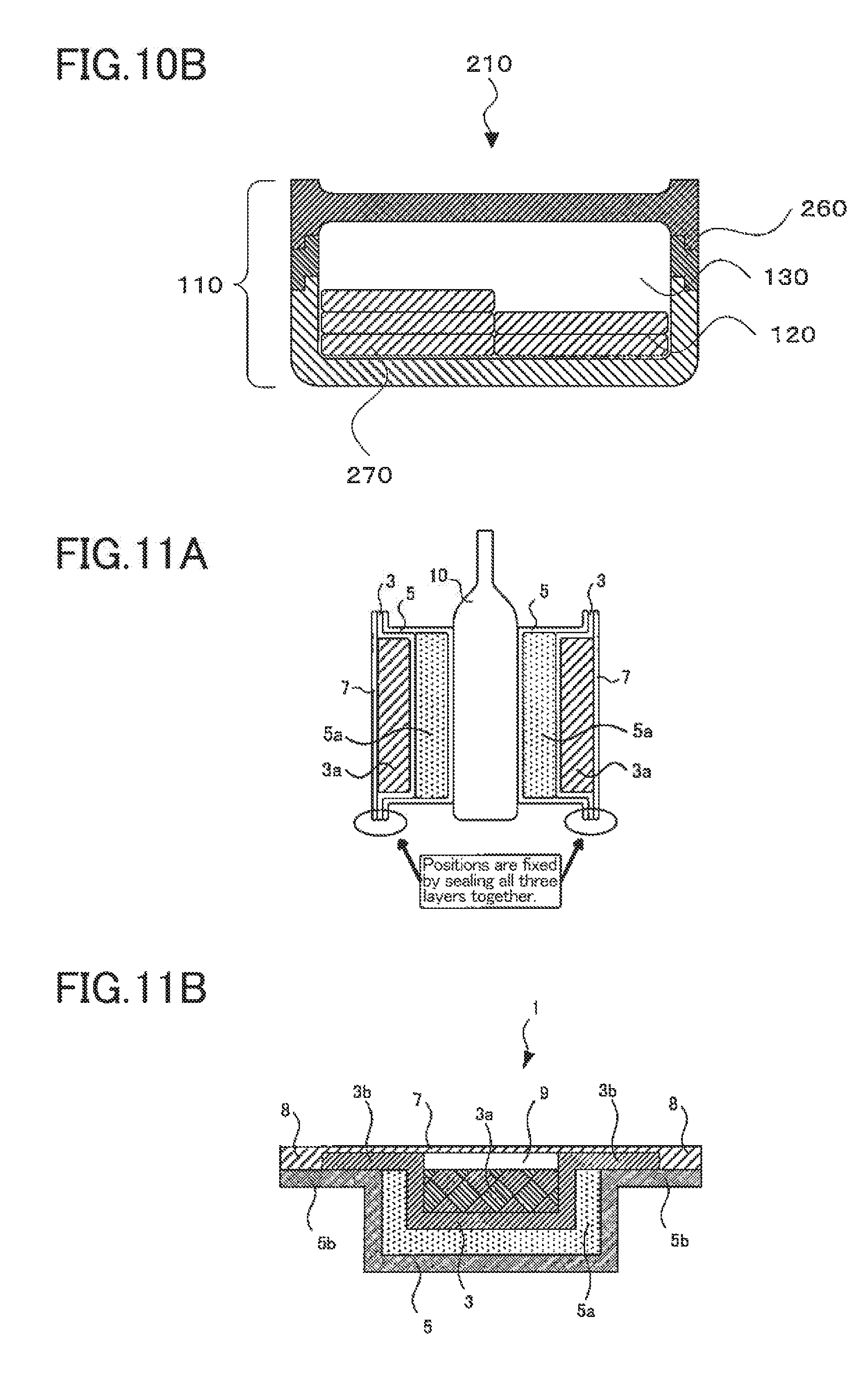
[0031] FIG. 10B is a cross-sectional view of the cold tray in accordance with the fifth embodiment.
[0032] FIG. 11A is a cross-sectional view of a usage of a red wine server in accordance with a sixth embodiment.
[0033] FIG. 11B is a cross-sectional view of a cold storage pack in accordance with the sixth embodiment.
[0034] FIG. 11C is a cross-sectional view of a usage of a conventional wine cooler sleeve.
[0035] FIG. 12A is an illustration of a concept for a first cold storage material (viscous).
[0036] FIG. 12B is an illustration of a concept for a first cold storage material (non-viscous).
[0037] FIG. 13A is a conceptual illustration of a step of manufacturing a first deep-drawing container.
[0038] FIG. 13B is a conceptual illustration of a step of manufacturing the first deep-drawing container.
[0039] FIG. 14A is a conceptual illustration of a step of manufacturing a second deep-drawing container.
[0040] FIG. 14B is a conceptual illustration of a step of manufacturing the second deep-drawing container.
[0041] FIG. 15 is a conceptual illustration of a step of pouring a second cold storage material (antifreeze material).
[0042] FIG. 16 is a conceptual illustration of a step of thermally compressing a film.
[0043] FIG. 17 is a schematic illustration of a step of pouring a first cold storage material (freezing material).
[0044] FIG. 18 is a conceptual illustration of a step of thermally compressing a film.
[0045] FIG. 19 is a schematic illustration of the procedures of a comparative experiment.
[0046] FIG. 20 is a diagram depicting an evaluation method in accordance with Comparative Experiment I.
[0047] FIG. 21 is a diagram depicting an evaluation method in accordance with Comparative Experiment.
[0048] FIG. 22 is a table listing the compositions and structures of antifreeze and freezing materials in accordance with Comparative Examples 1 to 4 and Examples 1 to 4.
[0049] FIG. 23 is a schematic illustration of how an antifreeze material is poured and packaged in Comparative Example 1.
[0050] FIG. 24A is a diagram representing Evaluation Results I obtained in Comparative Example 1.
[0051] FIG. 24B is a diagram representing Evaluation Results II obtained in Comparative Example 1.
[0052] FIG. 25A is a diagram representing Evaluation Results I obtained in Comparative Example 2.
[0053] FIG. 25B is a diagram representing Evaluation Results II obtained in Comparative Example 2.
[0054] FIG. 26A is a schematic illustration of how a cold storage pack is fabricated in Comparative Example 3.
[0055] FIG. 26B is a plan view of Comparative Example 3.
[0056] FIG. 26C is a side view of Comparative Example 3.
[0057] FIG. 27A is a diagram representing Evaluation Results I obtained in Comparative Example 3.
[0058] FIG. 27B is a diagram representing Evaluation Results II obtained in Comparative Example 3.
[0059] FIG. 28A is a diagram representing Evaluation Results I obtained in Comparative Example 4.
[0060] FIG. 28B is a diagram representing Evaluation Results II obtained in Comparative Example 4.
[0061] FIG. 29A is a diagram representing Evaluation Results I obtained in Example 1.
[0062] FIG. 29B is a diagram representing Evaluation Results II obtained in Example 1.
[0063] FIG. 30A is a diagram representing Evaluation Results I obtained in Example 2.
[0064] FIG. 30B is a diagram representing Evaluation Results II obtained in Example 2.
[0065] FIG. 31A is a diagram representing Evaluation Results I obtained in Example 3.
[0066] FIG. 31B is a diagram representing Evaluation Results II obtained in Example 3.
[0067] FIG. 32A is a diagram representing Evaluation Results I obtained in Example 4.
[0068] FIG. 32B is a diagram representing Evaluation Results II obtained in Example 4.
[0069] FIG. 33 is a table summarizing results of Comparative Examples 1 to 4 and Examples 1 to 4.
[0070] FIG. 34A is a graph representing a relationship between the amount of an antifreeze material and a performance thereof (time to target temperature).
[0071] FIG. 34B is a graph representing a relationship between the amount of an antifreeze material and a performance thereof (holding temperature).
[0072] FIG. 34C is a graph representing a relationship between the amount of an antifreeze material and a performance thereof (reached temperature).
[0073] FIG. 35A is a graph representing changes in wine temperature for different amounts of an antifreeze material, with the amount of freezing material being fixed at 100 grams.
[0074] FIG. 35B is a graph representing a relationship between the time taken for wine to reach 18.degree. C. and the amount of an antifreeze material.
[0075] FIG. 36A is a graph representing changes in wine temperature for packaging members that have different thermal conductivities.
[0076] FIG. 36B is a graph representing a relationship between the time taken for wine to reach 18.degree. C. and the thermal conductivity of packaging material.
[0077] FIG. 37 is a schematic illustration of how rapid cooling capability is investigated in relation to the amount of an antifreeze material and the thermal conductivity of a packaging member.
[0078] FIG. 38 is a table summarizing the weights of antifreeze and freezing materials used and the compositions of packaging materials.
[0079] FIG. 39 is a table summarizing the measurements of times to target temperature and holding times for different combinations of compositions of packaging materials and weights of antifreeze and freezing materials used.
[0080] FIG. 40 is a graph representing changes in liquid wine temperature for such combinations.
[0081] FIG. 41 is a set of diagrams representing liquid wine temperature distributions under Set of Conditions 2.
[0082] FIG. 42 is a set of diagrams representing results of investigation into TBAB's concentration dependency.
[0083] FIG. 43 is a graph representing a relationship between the concentration and onset temperature of melting of TBAB.
[0084] FIG. 44A is a schematic illustration of the structure of a red wine server in accordance with a seventh embodiment.
[0085] FIG. 44B is a schematic illustration of the structure of the red wine server in accordance with the seventh embodiment.
[0086] FIG. 45 is a diagram representing the measurements of the cool storage capability of the red wine server in accordance with the seventh embodiment.
DESCRIPTION OF EMBODIMENTS
[0087] The inventors of the present invention have found that an intervening buffer layer, when provided in a cooler container that comes with a thermal storage layer to maintain the temperature of a beverage, food material, or food product, regulates in accordance with ambient temperature the amount of heat either absorbed or released by the thermal storage layer and can hence render the temperature of an outer surface on the buffer layer side of the container differ from the melting point of a freezing material. The inventors have also found that the temperature of the outer surface on the buffer layer side of the container can be adjusted appropriately by adjusting the thickness of the buffer layer. These findings have led to the completion of the present invention.
[0088] The inventors have thus made it possible to deliver and maintain a suitable temperature for various food materials by simply changing either the amount of the freezing material or the thickness of the buffer layer, without having to replace the freezing material with a freezing material of another type. The following will describe embodiments of the present invention in more specific terms in reference to drawings.
First Embodiment
Structure of Cooler Container
[0089] A cooler container of an embodiment of the present invention has at least a region with a hollow structure and includes a thermal storage layer and a buffer layer both in the hollow region. The thermal storage layer contains a freezing material that changes phase at a specific temperature. The buffer layer is separated from the thermal storage layer in the hollow region and contains an antifreeze material that is a fluid at the phase transition temperature of the freezing material. FIG. 1A is a cross-sectional view of a cooler container 100 in accordance with the present embodiment. Referring to FIG. 1A, the cooler container 100 in accordance with the present embodiment has a region with a hollow structure inside a container body 110 and includes a thermal storage layer 120 and a buffer layer 130 both in the hollow region. In the present embodiment, an object to be cooled exchanges heat with the thermal storage layer 120 via the buffer layer 130. There is no partition or like structure between the thermal storage layer 120 and the buffer layer 130 in the present embodiment. A freezing material 150 and an antifreeze material 160 form separate layers without mingling, so that the thermal storage layer 120 and the buffer layer 130 are separated from each other. Alternatively, the container body 110 may have a partition in the hollow region to provide compartments and hence separate the thermal storage layer 120 and the buffer layer 130.
[0090] FIG. 1B is a cross-sectional view of an example usage of the cooler container 100 in accordance with the present embodiment. The cooler container 100 in accordance with the present embodiment may have, on an outer surface on the buffer layer 130 side of the container body 110, a placement surface 140 (top face) on which a food or food material is placed directly. When this is actually the case, the cooler container 100 is used by placing a food or food material directly on the placement surface 140 as shown in FIG. 1B. The food or food material placed on the placement surface 140 exchanges heat with the thermal storage layer 120 via the buffer layer 130 to stay at a suitable temperature.
[0091] The container body 110 has a hollow structure to encase, for example, the thermal storage layer 120 and the buffer layer 130. The container body 110 may be made of a resin material such as polyethylene, polypropylene, polyester, polyurethane, polycarbonate, polyvinyl chloride, or polyamide, a metal such as aluminum, stainless steel, copper, or silver, or an inorganic material such as glass, chinaware, or ceramic. The container body 110 is preferably made of a resin material in view of ease of manufacture and durability of the hollow structure and also because a thermochromic substance, which indicates that a suitable temperature has been reached, can be attached to the container body 110 in the form of a sticker or kneaded into the resin in order to enable a person to determine that a suitable temperature has been reached. The container body 110 may be provided, on an outer surface on the thermal storage layer 120 side thereof, with a thermal insulation layer of a thermal insulator. The provision of the thermal insulation layer does not affect heat exchange between the thermal storage layer 120, the buffer layer 130, and the object to be cooled and still reduces other heat transfer, which in turn increases the holding time.
[0092] The thermal storage layer 120 contains the freezing material 150, which changes phase at a specific temperature. The freezing material 150, intended for use with at least food and food materials, is preferably made of a substance that changes phase at a temperature in a range of from -20.degree. C. to 80.degree. C. like those listed in the table in FIG. 2B. In addition, the freezing material 150, used with food, is preferably made of a low toxicity substance such as water, potassium chloride, or sodium acetate for health and safety reasons. If the freezing material 150 is not to be replaced, the freezing material 150 preferably contains an additional preservative. The material that forms the thermal storage layer 120 preferably contains a supercooling inhibitor. The supercooling inhibitor preferably has a solubility that abruptly decreases near the phase transition temperature of the freezing material 150 in such a manner that the inhibitor can precipitate and facilitate the formation of crystal cores of the freezing material 150. Additionally, the supercooling inhibitor preferably has low toxicity for health and safety reasons. In view of these requirements, if the freezing material 150 is, for example, water or an aqueous solution of potassium chloride, the supercooling inhibitor may be alum or disodium hydrogen phosphate among other examples.
[0093] The buffer layer 130 contains the antifreeze material 160, which is a fluid at the phase transition temperature of the freezing material 150, and is separated from the thermal storage layer 120 in the hollow region of the container body 110. Materials for the antifreeze material 160 should have a smaller specific gravity than the freezing material 150, be fluidic (either liquid or gaseous) at the phase transition temperature of the freezing material 150, and not mingle with the freezing material 150. As an example, when the freezing material 150 is water, the antifreeze material 160 may be air. If there is provided a partition or like structure inside the hollow region of the container body 110 to form separate regions for the thermal storage layer 120 and the buffer layer 130, the antifreeze material 160 only needs to be fluidic at the phase transition temperature of the freezing material 150.
Method of Manufacturing Cooler Container
[0094] Next will be described a method of manufacturing the cooler container 100 in accordance with the present embodiment. FIGS. 3A to 3C are conceptual illustrations of steps of manufacturing the cooler container 100 in accordance with the present embodiment. First, a container body 110 that has a region with a hollow structure, like the one shown in FIG. 3A, is prepared. The container body 110 is preferably equipped with an injection hole 170 through which a freezing material 150 and an antifreeze material 160 can be injected. Next, the freezing material 150 is injected through the injection hole 170 of the container body 110 as shown in FIG. 3B. The freezing material 150 may be injected by any method. If the container body 110 is held in such a manner that the injection hole points upward, the freezing material 150 can be injected by its own weight.
[0095] Referring to FIG. 4, the container body 110 preferably has a scale 180 indicating the amount of liquid or a temperature estimated from the amount of liquid. The scale allows for easy adjustment of the amount of liquid. If a preservative or supercooling inhibitor is to be added, these additives may be either added to the freezing material 150 before the freezing material 150 is injected or added after the freezing material 150 is injected.
[0096] If the buffer layer 130 is to be formed of air, the amount of the freezing material 150 injected is adjusted to less than the volume of the hollow of the container, and the container is sealed as will be detailed later, so that some air can remain in the hollow to form the buffer layer 130. If the buffer layer 130 is to be formed of a non-air substance, the amount of the freezing material 150 injected is adjusted, the antifreeze material 160 is injected into the remaining volume, and the container is sealed. Materials for the antifreeze material 160 should have a smaller specific gravity than the freezing material 150, be fluid at the phase transition temperature of the freezing material 150, and not mingle with the freezing material 150. Using such a material that does not mingle with the freezing material 150 and has a smaller specific gravity than the freezing material 150, the antifreeze material 160 and the freezing material 150 form separate phases even when there is no partition or like structure provided in hollow region of the container body 110 as in the present embodiment. This arrangement facilitates the formation of the thermal storage layer 120 and the buffer layer 130.
[0097] The injection hole 170 of the container body 110 is then closed with a plug 190 as shown in FIG. 3C. The plug 190 may be provided, for example, by a conventional method such as ultrasonic welding or thermal welding or by placing a screw plug so that a user can freely open/close the container body 110 by hand. If the container body 110 is sealed, for example, by ultrasonic welding or thermal welding, the user cannot adjust the amounts of the freezing material 150 and the antifreeze material 160, but there is no possibility that the freezing material 150 or the antifreeze material 160 can leak out. If the plug 190 can be opened/closed freely by hand, the user can freely adjust the amounts of the freezing material 150 and the antifreeze material 160.
[0098] Finally, in an environment where temperature is less than or equal to the phase transition temperature of the freezing material 150, the cooler container 110 is placed still in such a manner that its bottom face becomes horizontal. The freezing material 150 thus solidifies so that at least the bottom face of the cooler container 110 and the top face of the thermal storage layer 120 become parallel to each other. The cooler container 100 of the present embodiment is manufactured by these manufacturing steps.
Example 1-1
[0099] Example 1-1 is a cold tray example in accordance with the first embodiment. A blow-molded container (container body) shown in FIG. 3A (substance: polyethylene; external dimensions: 220.times.140.times.t20 mm/t0.8 mm) was first prepared. Next, 200 grams of tap water was injected into the blow-molded container through an injection hole thereof using a liquid injector. The water filled approximately 45% of the internal volume of the blow-molded container. Finally, the injection hole was capped and sealed using an ultrasonic welder. A cold tray was hence manufactured that included a thermal storage layer of water and a buffer layer of air.
[0100] In an environment where temperature was less than or equal to the phase transition temperature of water, the obtained cold tray was placed still in such a manner that the bottom face of the tray became horizontal. Water thus solidified so that at least the bottom face of the tray and the top face of the thermal storage layer became parallel to each other. Specifically, the tray was placed still and horizontally in a freezer of a common, household refrigerator in such a manner that the bottom face of the tray came into contact with the internal bottom of the refrigerator. Twelve hours later when the cold tray was taken out, it was observed that the thermal storage layer had solidified. The cold tray had a height of 20 mm (the container material had a thickness of 0.8 mm), whereas the thermal storage layer had a thickness of approximately 7 mm, and the buffer layer had a thickness of approximately 11 mm.
[0101] Thermocouple wires were attached to the top and bottom faces of the cold tray in which the freezing material had solidified, to observe temperature changes over time at room temperature (25.degree. C.). Results are shown in FIG. 5. The temperature of the bottom face remained at approximately 1.degree. C. for 30 to 150 minutes from the start of the measurement. This is attributable to the ice/water phase transition temperature of the thermal storage layer, which is 0.degree. C. Meanwhile, the temperature of the top face over the buffer layer remained at approximately 8.degree. C., which was above the phase transition temperature of the thermal storage layer, for 30 to 120 minutes from the start of the measurement. It is hence ascertained that the provision of the intervening buffer layer in the cold tray alleviates the coldness of the thermal storage layer and makes it possible to set the temperature of the top face of the tray to a temperature that differs from the melting point of the freezing material.
Example 1-2
[0102] Example 1-2 is another cold tray example in accordance with the first embodiment. Example 1-2 is a cold tray of the same structure as Example 1-1, except that the former contains 350 grams of liquid as opposed to 200 grams of liquid in the latter. Example 1-2 was manufactured by the same method as Example 1, except for the change in the amount of liquid.
Comparative Example 1-1
[0103] Comparative Example 1-1 is a cold tray of the same structure as Example 1-1, except for a change in the amount of liquid contained in the cold tray from 200 grams to 450 grams (this amount of water substantially filled the container). Comparative Example 1-1 was manufactured by the same method as Example 1-1, except for the change in the amount of liquid.
Evaluation of Effects of Examples and Comparative Example
[0104] FIG. 6A shows the thicknesses of the thermal storage layer and the buffer layer in the cold tray after freezing. FIG. 6A demonstrates that the thickness, and hence the coldness buffering capability, of the buffer layer decrease in the sequence of Example 1-1, Example 1-2, and Comparative Example 1-1. FIG. 6B shows maintainable tray top face temperature plotted against the thickness of the buffer layer and demonstrates that the temperature of the top face of the tray increases linearly with an increase in the thickness of the buffer layer. The temperature of the top face of the tray can be readily adjusted through adjustment of the thickness of the buffer layer (or through adjustment of the amount of liquid in the thermal storage layer). It is hence possible to provide trays suited for temporary cooling of food and food materials without having to change the type of freezing material.
Second Embodiment
Structure of Cooler Container
[0105] FIG. 7 is a set of a cross-sectional view and a top view of a cooler container 100 in accordance with the present embodiment. As shown in FIG. 7, the cooler container 100 has a flat bottom face and a step-like top face. The cooler container 100 contains therein a thermal storage layer 120 that is maintained in a horizontal position. Therefore, the thickness of the buffer layer 130 can be adjusted by providing regions with a hollow structure of different thicknesses in the container body 110. The step-like surface shown in FIG. 7 may be replaced by a slope. In addition, the cooler container 100, when viewed from above, is rectangular in FIG. 7. Alternatively, the cooler container 100 may be circular or of any other shape where necessary when viewed from above.
Method of Manufacturing Cooler Container
[0106] The cooler container 100 in accordance with the present embodiment is manufactured by the same method as the cooler container 100 in accordance with the first embodiment, except for the shape of the container body 110.
Example 2-1
[0107] Example 2-1 is a cold tray example in accordance with the second embodiment. A blow-molded container was first prepared that had a cross-sectional shape shown in FIG. 7 and that had the same container width, container depth, and resin thickness as in Example 1. The hollow regions had a thickness of 31 mm, 25 mm, and 20 mm respectively. Water (450 grams) as a freezing material was injected into this blow-molded container, and the container was sealed.
[0108] The blow-molded container was frozen in the same manner as in Example 1-1, to evaluate the thicknesses of the thermal storage layer and the buffer layer. The thermal storage layer had a thickness of 20 mm. The buffer layer had a thickness of 11 mm, 5 mm, and 0 mm in the respective hollow regions where the thickness was 31 mm, 25 mm, and 20 mm. The top face of the tray had a temperature of 8.degree. C., 4.degree. C., and 0.degree. C. in the respective hollow regions where the thickness was 31 mm, 25 mm, and 20 mm. These measurements demonstrate that this single cold tray can provide a plurality of regions of different temperatures. It is hence possible to maintain a plurality of food materials at different suitable temperatures by using the single tray. The tray is suitable to serve hors d'oeuvre.
Third Embodiment
Structure of Cutting Board
[0109] A cooler container in accordance with an embodiment of the present invention is applied to a cutting board in the present embodiment. FIG. 8 is a cross-sectional view of a cutting board 200 in accordance with the present embodiment. In the present embodiment, a plug 190 for an injection hole 170 through which a freezing material 150 is injected is a screw plug. This structure enables the user to freely open/close the injection hole 170 to adjust the amount of liquid therein. Otherwise, the cutting board 200 is structured in the same manner as the first embodiment. The material for the container body has a thickness that is suited for the usage of the cutting board 200.
Method of Manufacturing Cutting Board
[0110] The cutting board 200 in accordance with the present embodiment is manufactured by the same method as the cooler container 100 in accordance with the first embodiment is manufactured.
Example 3-1
[0111] Example 3-1 is a cutting board example in accordance with the third embodiment. A blow-molded container (substance: polyethylene: external dimensions: 230.times.400.times.t20 mm/t2 mm) was first prepared. Next, 600 grams of water was injected into this container, which was then closed using a screw plug. The container was then frozen in a freezer as in Example 1, after which the respective thicknesses of the buffer layer and the thermal storage layer were measured to be 11 mm and 5 mm. The temperature of the surface on which a food material was to be cut (top face) was measured. The measurement demonstrated that the temperature of the top face remained at 8.degree. C.
[0112] Mozzarella cheese could be cut into desired shapes on this cutting board. For a comparison, two cutting boards were prepared, one of them being an ordinary wooden cutting board (top face temperature: 25.degree. C.) as Comparative Example 3-1 and the other being a cutting board (top face temperature: 0.degree. C.) as Comparative Example 3-2. The cutting board as Comparative Example 3-2 was built from the same container as in Example 3-1, albeit without a buffer layer, filled with water, and then frozen. Some of the cheese melted and stuck to the cutting board of Comparative Example 3-1 and could not be cut as desired. Some of the cheese froze on the cutting board of Comparative Example 3-2 where the cheese was in contact with the cutting board.
[0113] It is hence possible to cut, into desired shapes at suitable temperature on the cutting board of the present example, those food materials which are so rich in fat like cheese that they can soften/harden or change shape with temperature. Additionally, since the temperature of the cutting board of the present example can be readily altered to match suitable temperature by simply changing the amount of liquid in the thermal storage layer before freezing, it is possible to cut various food materials, including tuna partially thawed at 0.degree. C., on a single cutting board.
Fourth Embodiment
[0114] A cooler container in accordance with an embodiment of the present invention is applied to a cold tray in the present embodiment. FIG. 9 is a cross-sectional view of a cold tray 210 in accordance with the present embodiment. The cooler container 100 as it is may be used as a cold tray in the first and second embodiments if the cooler container 100 has a placement surface 140. In the present embodiment, the cooler container 100 has a placement surface 140 and is detachable. The temperature of the cold tray of the present embodiment can be adjusted by replacing the cooler container 100 with another one.
Structure of Cold Tray
[0115] Referring to FIG. 9, the cold tray 210 in accordance with the present embodiment has a region with a hollow structure inside a container body 110 and includes a thermal storage layer 120 and a buffer layer 130 both in the hollow region. The cold tray 210 includes the cooler container 100, an external packaging section 220, and a cooler container fixing section 230. The cooler container 100 has, on an outer surface on the buffer layer 130 side thereof, the placement surface 140 on which a food or food material is directly placed. The external packaging section 220 houses the cooler container 100. The cooler container fixing section 230 fixes the cooler container 100 and the external packaging section 220. Other members of the cold tray 210 such as the container body 110, the thermal storage layer 120, and the buffer layer 130 have the structure discussed above.
[0116] The external packaging section 220, housing the cooler container 100, is as a whole used as the cold tray 210. The external packaging section 220 may be formed of a resin material, metal, or inorganic material similarly to the container body 110. The cooler container fixing section 230 may be made of any material and disposed in any location so long as the cooler container fixing section 230 can fix the cooler container 100 and the external packaging section 220. The external packaging section 220 may have such a shape that it can fix the cooler container 100.
[0117] In this structure in which the cooler container 100, provided thereon with the placement surface 140, is fixed to the external packaging section 220 in a detachable manner, a suitable temperature for a food material can be achieved simply by replacing the cooler container 100 with another one designed for that suitable temperature. This saves trouble in altering the types and amounts of the freezing material 150 and the antifreeze material 160 in the cooler container 100. In addition, since the cold tray 210 includes the cooler container 100 and the external packaging section 220, and the cooler container 100 does not need to perform the function of the external packaging section 220, the cooler container 100 can be made relatively compact as compared with a cooler container 100 that is itself used as a cold tray. The cooler container 100 may be structured to allow adjustment of the types and amounts of the freezing material 150 and the antifreeze material 160. Although FIG. 9 shows the buffer layer 130 having a constant thickness in the cooler container 100, the buffer layer 130 may have a different thickness from region to region of the cooler container 100 as described in the second embodiment.
Fifth Embodiment
[0118] A cooler container in accordance with an embodiment of the present invention is applied to a cold tray in the present embodiment. FIGS. 10A and 10B are cross-sectional views of a cold tray 210 in accordance with the present embodiment. A container body 110 in the present embodiment can be separated into an upper tray 240 and a lower tray 250. The upper tray 240 and the lower tray 250, when combined, form a region with a hollow structure inside the container body 110.
Structure of Cold Tray
[0119] Referring to FIG. 10A, the cold tray 210 in accordance with the present embodiment has a region with a hollow structure inside the container body 110 formed by combining the upper tray 240 and the lower tray 250. The cold tray 210 includes a thermal storage layer 120 and a buffer layer 130 both in the hollow region. The cold tray 210 further includes, on the outer surface on the buffer layer 130 side thereof (i.e., on the top face of the upper tray 240), a placement surface 140 on which a food or food material is directly placed.
[0120] The upper tray 240 has the placement surface 140 on the top face thereof. The bottom face of the upper tray 240, when the upper tray 240 is combined with the lower tray 250, provides a top section of the hollow structure in the container body 110. The lower tray 250 has a portion that is to contain a freezing material 150 therein. The thermal storage layer 120 is formed by injecting the freezing material 150 into the lower tray 250 and solidifying the freezing material 150 therein. When the upper tray 240 and the lower tray 250 are combined, the layer of air from the top face of the thermal storage layer 120 to the bottom face of the upper tray 240 forms the buffer layer 130. The upper tray 240 and the lower tray 250 are preferably connectable in a hermetically sealed manner in order to prevent air from coming in and going out and hence stabilize temperature. Since the upper tray 240 and the lower tray 250 are separable, the inner surface of the container body 110 is readily washable. The cold tray 210 in accordance with the present embodiment can therefore be kept clean.
[0121] The container body 110 of the cold tray 210 in accordance with the present embodiment may include a spacer 260 as shown in FIG. 10B. The inclusion of the spacer 260 enables adjustment of the thickness of the buffer layer 130. Additionally, in the cold tray 210 in accordance with the present embodiment, the thermal storage layer 120 may be formed using a freezing material pack 270 in which the freezing material 150 is packaged by a conventional method, instead of being formed by injecting the freezing material 150 into the lower tray 250. When this is actually the case, it is only the freezing material pack 270 that needs to be cooled down to the phase transition temperature of the freezing material 150 or below. Therefore, there is no longer a need to cool the whole cold tray 210 or lower tray 250 down to the phase transition temperature of the freezing material 150 or below. In addition, the thicknesses of the thermal storage layer 120 and the buffer layer 130 can be adjusted by changing the number of freezing material packs 270 provided on each portion of the lower tray 250. The buffer layer 130 may be formed using an antifreeze material pack (not shown) in which the antifreeze material 160 is packaged. The use of an antifreeze material pack facilitates the fabrication of the buffer layer 130 when the antifreeze material 160 includes a non-air material.
Sixth Embodiment
Structure of Red Wine Server
[0122] A red wine server in accordance with an embodiment of the present invention includes at least one cold storage pack. FIG. 11A is a cross-sectional view of a usage of a red wine server in accordance with the present embodiment. The cold storage pack includes a first deep-drawing container 3 as a first container section and a second deep-drawing container 5 as a second container section. The second container section is enclosed by the first container section to form a double-layered structure.
[0123] The first deep-drawing container 3 contains a first cold storage material (freezing material) 3a, and the second deep-drawing container 5 contains a second cold storage material (antifreeze material) 5a. The second cold storage material (antifreeze material) 5a remains in liquid phase at the phase transition temperature of the first cold storage material (freezing material) 3a. The second cold storage material (antifreeze material) 5a is positioned in intimate contact with a wine bottle 10. A lid member 7 closes the first deep-drawing container 3.
[0124] FIG. 11B is a cross-sectional view of a cold storage pack 1 in accordance with the present embodiment. Referring to FIG. 11B, in the cold storage pack 1, the first deep-drawing container 3 has a flange section 3b, and the second deep-drawing container 5 has a flange section 5b. The flange section 3b is joined to the flange section 5b and also to the lid member 7. There exists a cavity layer 9 between the lid member 7 and the first cold storage material 3a.
[0125] As described here, the second cold storage material 5a remains in liquid phase at the phase transition temperature of the first cold storage material 3a, and the second deep-drawing container 5 is brought into contact with the wine bottle 10. Therefore, the second deep-drawing container 5 can be brought into intimate contact with the wine bottle 10. Meanwhile, Patent Literature 3 proposes a wine cooler sleeve with a fixing means that enables a cold insulator to be removably attached to the inner wall of a cooler container. This conventional wine cooler sleeve does not include a structure in which the cold insulator is brought into intimate contact with the wine bottle. The conventional wine cooler sleeve therefore fails to quickly bring wine to an optimum drinking temperature. In contrast, the present embodiment, according to which the second deep-drawing container 5 can be brought into intimate contact with the wine bottle 10, can quickly bring wine to an optimum drinking temperature.
[0126] FIG. 11C is a cross-sectional view of a usage of a conventional wine cooler sleeve. Referring to FIG. 11C, if the second cold storage material 5a is enclosed by the first cold storage material 3a (hereinafter, this structure may be referred to as a "pack-in-pack structure") in the conventional cold storage pack, the first cold storage material may move vertically downward under gravity during use, which could create, in an upper portion of the wine bottle 10, a region in which there is no cold storage material. Heat would escape through this region, possibly hindering the wine bottle 10 from being quickly brought to a desirable temperature.
[0127] In contrast, as shown in FIGS. 11A and 11B, in the cold storage pack 1 in accordance with the present embodiment, the first deep-drawing container 3 containing the first cold storage material 3a and the second deep-drawing container 5 containing the second cold storage material 5a are fixed by the flange section 3b and the flange section 5b. Therefore, the positional relationship of the two cold storage materials can be maintained over time, irrespective of effects of their weight.
[0128] The particular structure described here enables the sensible heat stored by the second cold storage material 5a to be reliably transmitted to the wine bottle 10. The wine bottle 10 is hence quickly brought to a desirable temperature. The structure also enables the sensible and latent heat stored by the first cold storage material 3a to be reliably transmitted to the wine bottle 10 via the second cold storage material 5a. The wine bottle 10 is hence helped to be quickly brought to a desirable temperature and can be maintained at the desirable temperature for an extended period of time.
Cold Storage Material
[0129] FIG. 12A is an illustration of a concept for the first cold storage material used in a cold storage pack in accordance with the present embodiment when the cold storage material is viscous. FIG. 12B is an illustration of a concept for the first cold storage material when the cold storage material is non-viscous. In the cold storage pack in accordance with the present embodiment, the first cold storage material (freezing material) and the second cold storage material (antifreeze material) have such viscosity that the materials can maintain shape under their own weight.
[0130] Referring to FIG. 12B, if a non-viscous cold storage material is used in a cold storage pack disposed upright for the temperature management of an object to be cooled, the cold storage material is displaced vertically downward under gravity as the cold storage material changes from solid to liquid. The displacement inhibits adequate temperature management of an upper part of the object to be cooled. The downward displacement of the cold storage material also leaves a cavity vertically above the cold storage material. Heat could flow in or out through the cavity, disrupting the cooling effect of the cold storage pack.
[0131] Accordingly, a viscous cold storage material is used as in FIG. 12A to reduce the influence of gravity to a minimum. That increases the contact area between the cold storage pack and the object to be cooled, thereby enabling efficient heat exchange.
[0132] In order to impart a cold storage material with such a viscosity that the cold storage material receives little influence of gravity, a thickening agent needs to be added in a large quantity. However, if an excessively large amount of thickening agent is added to the cold storage material, the inherent capability of the cold storage material will be negatively affected. Accordingly, the first cold storage material and the second cold storage material in the cold storage pack in accordance with the present embodiment are given a low viscosity of approximately 1,000 cP (e.g., paint). This level of viscosity enables adequate temperature management of the object to be cooled even if the cold storage pack is disposed upright for the temperature management of the object to be cooled as shown in FIG. 12A.
Method of Manufacturing Cold Storage Pack
[0133] Next will be described a method of manufacturing a cold storage pack used in the red wine server in accordance with the present embodiment. The cold storage pack is manufactured in a stirring and press-through-packing machine. A method of manufacturing the cold storage pack involves at least the steps of molding a concave, first deep-drawing container (first container section) in a first metal mold; molding a second deep-drawing container (second container section) in a second metal mold, the second deep-drawing container having a concave shape at least larger than the concave shape of the first deep-drawing container; pouring, into the first deep-drawing container, a first cold storage material (freezing material) that changes phase at a predetermined temperature: pouring, into the second deep-drawing container, a second cold storage material (antifreeze material) that remains in liquid phase at the phase transition temperature of the freezing material; and placing the second deep-drawing container containing the second cold storage material (freezing material) in the first deep-drawing container containing the first cold storage material (freezing material) and joining a lid member and flange sections of the first and second deep-drawing containers.
[0134] Alternatively, the cold storage pack may be manufactured by a method involving at least the steps of: molding a concave, first deep-drawing container (first container section) in a first metal mold; molding a second deep-drawing container (second container section) in a second metal mold, the second deep-drawing container having a concave shape at least larger than the concave shape of the first deep-drawing container, pouring, into the second deep-drawing container, a second cold storage material (antifreeze material) that remains in liquid phase at the phase transition temperature of the first cold storage material (freezing material); placing the second deep-drawing container containing the second cold storage material inside the first deep-drawing container containing the first cold storage material; pouring, into the first deep-drawing container, the first cold storage material that changes phase at a predetermined temperature; and joining a lid member and the flange sections of the first and second deep-drawing containers.
[0135] FIGS. 13A and 13B are conceptual illustrations of steps of manufacturing the first deep-drawing container. Referring to FIG. 13A, a hard film 31 is disposed in a vacuum-molding metal mold 30 as the first metal mold and vacuum-molded in a vacuum forming machine.
[0136] The first deep-drawing container, since being located between the lid member and the second deep-drawing container, is typically composed of, for example, a three-layer (e.g., PE//NY//PP) film. However, a three-layer film could lead to unstable sealing strength. Especially, in a general heat sealer, there is a heater only on one side of a sealer. Therefore, the film sealed on the no-heater side has a reduced sealing strength, which is undesirable. Three-layer films are also disadvantageous in that they are less available in the market, require more steps to manufacture, and are more costly than two-layer films. Therefore, the first deep-drawing container in accordance with the present embodiment is molded purposefully from a two-layer film and provided with a through hole in a part of the film.
[0137] The concave, first deep-drawing container (first container section) 3 is fabricated by the steps described here as shown in FIG. 13B.
[0138] FIGS. 14A and 14B are conceptual illustrations of steps of manufacturing the second deep-drawing container. Referring to FIG. 14A, a soft film 51 is disposed in a vacuum-molding metal mold 50 as the second metal mold and vacuum-molded in a vacuum forming machine.
[0139] FIG. 15 is a conceptual illustration of a step of pouring a second cold storage material (antifreeze material). In this step, a predetermined amount of the second cold storage material (antifreeze material) 5a is poured, using a liquid injector, into a second deep-drawing container 5 fabricated as described earlier. The liquid injector is preferably a pump-based injector. The second cold storage material preferably has as low a viscosity as possible so long as the viscosity does not cause the materials to bounce, fly off, or otherwise disturb the pouring process and enables the second cold storage material to preserve its shape under its own weight. The second cold storage material preferably has a viscosity of, for example, approximately 1,000 to 10,000 cP. A viscous, second cold storage material can achieve a high filling rate.
[0140] FIG. 16 is a conceptual illustration of a step of thermally compressing a film. In this step, a first deep-drawing container 3 fabricated as described earlier is positioned on the second deep-drawing container 5 containing the second cold storage material (antifreeze material), and a film from which the first deep-drawing container 3 is molded and a film material from which the second deep-drawing container 5 is molded are thermally welded. A heat sealer is preferably used in the thermal compression (thermocompression) of this film. Alternatively, an ultrasonic welder may be used.
[0141] FIG. 17 is a schematic illustration of a step of pouring a first cold storage material (freezing material) 3a. In this step, a predetermined amount of the first cold storage material 3a is poured, using a liquid injector, into the first deep-drawing container 3 fabricated as described earlier. The liquid injector is preferably a pump-based injector. The first cold storage material (freezing material) 3a preferably has a viscosity that enables the first cold storage material 3a to preserve its shape under its own weight. The first cold storage material 3a more preferably has a viscosity of, for example, approximately 1,000 to 10,000 cP. A viscous, first cold storage material can achieve a high filling rate. The cold storage material has a filling rate of approximately 70 to 90% with respect to the capacity of the container. There is preferably provided a cavity layer between the cold storage material and the top face of the container.
[0142] FIG. 18 is a conceptual illustration of a step of thermally compressing a film. In this step, a lid member 7 is positioned on the second deep-drawing container 5, and the lid member 7 and a film material from which the second deep-drawing container 5 is molded are thermally welded. A heat sealer is preferably used in the thermal compression (thermocompression) of this film. Alternatively, an ultrasonic welder may be used. The lid member 7 is preferably formed of a soft plastic film.
[0143] There is preferably provided a through hole 8 in a part of the top face of the film from which the second deep-drawing container 5 is molded, so that the lid member 7 is, in this step, welded via the through hole 8 to the film from which the first deep-drawing container 3 is molded.
[0144] By joining the first deep-drawing container and the second deep-drawing container in this manner, the positional relationship of the first deep-drawing container and the second deep-drawing container is fixed, which can in turn improve performance and repeatability. The second deep-drawing container may have such a bottom face that the depth of the container can vary as shown in FIGS. 14A to 18. For example, the second deep-drawing container, if having a depth that grows stepwise in the height direction, comes into improved contact with a heat-receiving body (food or beverage) that is narrow in the middle like a wine bottle when traced along its height. The first deep-drawing container and the second deep-drawing container are joined by welding as described above; examples include ultrasonic welding, vibration welding, induction welding, high frequency welding, semiconductor laser welding, thermal welding, and spin welding. These are mere examples and do not limit an embodiment of the present invention.
[0145] The method described above can manufacture a cold storage pack in which: the second cold storage material remains in liquid phase at the phase transition temperature of the first cold storage material; and the second deep-drawing container is brought into contact with a food and beverage that is a heat-receiving body.
Maximum Weight of Freezing and Antifreeze Materials Used in Red Wine Server
[0146] Here is a list of parameters that have a somewhat limited value/range of values in a red wine server in accordance with the present embodiment.
[1] Values Related to Wine and Wine Bottle
[0147] (1) Wine volume: 750 mL
[0148] (2) Bottle weight (including wine): 1,200 to 1,500 grams
[0149] (3) Bottle type: Bordeaux (external dimensions: 070 to 80 mm; height: 290 to 300 mm; height of non-narrow, flat section: 180 to 200 mm; surface area of bottle in contact with antifreeze material in red wine server: .apprxeq.45,000 mm.sup.2)
[0150] (4) Optimum drinking temperature: 14 to 18.degree. C.
[2] Properties of Packaging Material for Packaging Antifreeze Material and Freezing Material
[0151] (1) Substance: ONY//LLDPE (typically, nylon and low-density polyethylene)
[0152] (2) Thickness: 50 to 60 um (these values are typical and highly available in the market)
[0153] (3) Thermal conductivity: 0.33 W/mK
[0154] Next, an approximate maximum combined weight of the freezing and antifreeze materials used in the red wine server in accordance with the present embodiment is specified based on the weight perception given by Weber's law. According to Weber's law, the "just noticeable difference" (or differential threshold) between two stimuli for a human is proportional to the stimulus intensity. There are some documents and research papers that verify this law from the "weight perception" viewpoint. The just noticeable difference can vary depending on the shape of the object and how the object is held (see Tokyo Women's Medical University Journal: 876-880, 1976). The following findings are safely presumed to hold true.
[0155] Letting the weight of an object be an equivalent of the base weight (R), and the minimum weight difference from the base weight (R) that a human can perceive be an equivalent of the differential threshold (.DELTA.R), it then follows From Weber's law that the Weber fraction (.DELTA.R/R) is in the range of 0.05 to 0.2.
[0156] Next, using the parameter values given above, an approximate range of the tolerable combined weight of the freezing and antifreeze materials in the red wine server in accordance with an embodiment of the present invention is calculated against the weight of a wine bottle (with wine (liquid amount)).
[0157] Assume that a wine bottle (with wine (liquid amount)) weighs 1,500 grams and that the Weber fraction is equal to 0.2, which is a maximum. It then follows that the minimum weight that a human can perceive against the base weight (1,500 grams) is given by 1,500.times.0.2=300 grams. It is hence concluded that the combined weight of the freezing and antifreeze materials in the red wine server in accordance with embodiments is preferably less than or equal to 300 grams.
Comparative Experiment
[0158] Next, comparative experiments were conducted by setting target specifications as follows for the red wine server in accordance with the present embodiment: the holding temperature was from 14 to 18.degree. C., the time to target temperature (i.e., time to the holding temperature) was less than or equal to 20 minutes, and the holding time at the holding temperature was greater than or equal to 120 minutes. The following will describe two comparative experiments (Comparative Experiments I and II) that were conducted in order to investigate the effects of the red wine server in accordance with the present embodiment. FIG. 19 is a schematic illustration of the procedures of a comparative experiment.
[1] Comparative Experiment I
Procedures I
[0159] (1) A wine bottle (content: 750 mL of water) was prepared in which water was maintained at normal temperature (around 25.degree. C.).
[0160] (2) Either a freezing or antifreeze material cooled (frozen) in a freezer (at approximately -18.degree. C.) or both was/were attached around the wine bottle.
[0161] (3) A thermal insulator was attached around the cold storage material (i.e., either a cooled (frozen) freezing or antifreeze material or both) on the bottle. The thermal insulator was general-purpose "AL vapor deposition+foamed PE."
[0162] (4) The wine bottle was put in a 25.degree. C. thermal insulation chamber. Changes in water temperature in the middle portion of the bottle were measured.
Evaluation Method I
[0163] FIG. 20 is a diagram depicting an evaluation method in accordance with Comparative Experiment I. The time for the liquid temperature to reach the target temperature from the start of wine cooling (time to target temperature) and the holding time were measured. The target temperature was a maximum optimum drinking temperature for red wine (18.degree. C.). Results obtained by Evaluation Method I will be hereinafter referred to as Evaluation Results I.
[2] Comparative Experiment II
Procedures II
[0164] (1) A wine bottle (content: 750 mL of water) was prepared in which water was maintained at an optimum drinking temperature (14 to 18.degree. C.).
[0165] (2) Either a freezing or antifreeze material cooled (frozen) in a freezer (at approximately 3 to 5.degree. C.) or both was/were attached around the wine bottle.
[0166] (3) A thermal insulator was attached around the cold storage material (i.e., either a cooled (frozen) freezing or antifreeze material or both) on the bottle. The thermal insulator was general-purpose "AL vapor deposition+foamed PE."
[0167] (4) The wine bottle was put in a 25.degree. C. thermal insulation chamber. Changes in water temperature in the middle portion of the bottle were measured.
Evaluation Method II
[0168] FIG. 21 is a diagram depicting an evaluation method in accordance with Comparative Experiment II. The liquid temperature holding time from the start of wine cooling ("holding time") was measured. The holding temperature here was a maximum optimum drinking temperature for red wine (18.degree. C.). Results obtained by Evaluation Method II will be hereinafter referred to as Evaluation Results II.
[0169] FIG. 22 is a table listing the compositions and structures of antifreeze and freezing materials in accordance with Comparative Examples 1 to 4 and Examples 1 to 4. Antifreeze and freezing materials were prepared in Comparative Examples 1 to 4 and Examples 1 to 4 as shown in FIG. 22, and Evaluations I and II were performed by Procedures I and II described above. Each cold storage pack was attached in a different manner in Comparative Examples 1 to 4 and Examples 1 to 4 as shown in FIG. 22.
Comparative Example 1
[0170] FIG. 23 is a schematic illustration of how an antifreeze material is poured and packaged in Comparative Example 1.
[0171] (A) Put tap water and NaCl (sodium chloride) into a stirring chamber and stir the content at 150 rpm/10 min. to dissolve the sodium chloride and obtain a 23 wt % aqueous solution of NaCl.
[0172] (B) Turn on a pump. Pack, in a film, the aqueous solution prepared in (A) using a vertical form-fill seal machine, to fabricate an antifreeze member (thermal storage package, a total weight of 300 grams). A film of ONY_10 um/LLDPE_50 um was used as the film in the packing.
[0173] Results of evaluation in Comparative Example 1 are presented and discussed next. FIG. 24A is a diagram representing Evaluation Results I obtained in Comparative Example 1. The diagram demonstrates that the antifreeze member attaches well to the wine bottle. However, since the materials do not freeze, the antifreeze member has a low cooling capability, failing to cool the content down to its maximum optimum drinking temperature of 18.degree. C.
[0174] FIG. 24B is a diagram representing Evaluation Results II obtained in Comparative Example 1. The diagram demonstrates that the antifreeze member attaches well to the wine bottle. However, since the materials do not freeze, the antifreeze member has a low cooling capability, allowing liquid temperature to rise with time. The antifreeze member can keep the red wine at or below its maximum optimum drinking temperature of 18.degree. C. for no longer than 30 minutes.
Comparative Example 2
[0175] A freezing material was prepared containing a 41 wt % aqueous solution of TBAB (tetrabutylammonium bromide) by the same procedures as in Comparative Example 1. A freezing member (thermal storage package, a total weight of 300 grams) was fabricated using a stirring chamber and a packaging machine.
[0176] Results of evaluation in Comparative Example 2 are presented and discussed next. FIG. 25A is a diagram representing Evaluation Results I obtained in Comparative Example 2. The diagram demonstrates that since the materials produce freezing latent heat, the freezing member has a higher cooling capability than Comparative Example 1, enabling the red wine to reach an optimum drinking temperature. However, since the materials are frozen, the freezing member attaches poorly to the wine bottle. Both the time to target temperature and the holding time are insufficient.
[0177] FIG. 25B is a diagram representing Evaluation Results II obtained in Comparative Example 2. The diagram demonstrates that since the materials produce melting latent heat at approximately 12.degree. C., the red wine can be maintained at an optimum drinking temperature for approximately 100 minutes from the start of the measurement. However, this structure alone is short of maintaining wine that is initially around normal temperature at a proper optimum drinking temperature (14 to 18.degree. C.), similarly to Evaluation Results I of Comparative Example 2.
Comparative Example 3
[0178] FIG. 26A is a schematic illustration of how a cold storage pack is fabricated in Comparative Example 3. FIG. 26B is a plan view of Comparative Example 3. FIG. 26C is a side view of Comparative Example 3. An antifreeze material (23 wt % aqueous solution of NaCl (sodium chloride)) was prepared by the same method as in Comparative Example 1. A freezing material (41 wt % aqueous solution of TBAB (tetrabutylammonium bromide)) was prepared by the same method as in Comparative Example 2. A pack-in-pack cold storage member (cold storage pack) containing, in a film pack, an antifreeze material and a packed-in-film cold storage material was fabricated using a vertical form-fill seal machine shown in FIG. 26A. A film of ONY_10 um/LLDPE_50 um was used in the packing.
[0179] Results of evaluation in Comparative Example 3 are presented and discussed next. FIG. 27A is a diagram representing Evaluation Results I obtained in Comparative Example 3. The diagram demonstrates that the combination of an antifreeze material and a freezing material in which the antifreeze material attaches well to the wine bottle and the freezing material achieves sufficient cooling performance remarkably and advantageously reduces time to target temperature from 50 minutes in Comparative Example 2 to 25 minutes. The combination also improves holding time from 40 minutes to 95 minutes. In this structure, however, the freezing material and the antifreeze material are packaged in one film pack, but not fixed. A gap therefore forms as shown in FIG. 11C, which decreases heat exchange efficiency.
[0180] FIG. 27B is a diagram representing Evaluation Results II obtained in Comparative Example 3. The diagram demonstrates that the combination of an antifreeze material and a freezing material in which the antifreeze material attaches well to the wine bottle and the freezing material achieves sufficient cooling performance achieves a sufficient reached temperature of 14.degree. C. in comparison with Comparative Examples 1 and 2 and a holding time equivalent to that in Comparative Example 2. However, this structure forms a gap similarly to Evaluation Results I of Comparative Example 3, which decreases heat exchange efficiency.
Comparative Example 4
[0181] A cold storage member (cold storage pack) was fabricated in a stirring and press-through-packing machine. The antifreeze material was a 23 wt % aqueous solution of NaCl (sodium chloride), and the freezing material was a 20 wt % aqueous solution of KCl (potassium chloride).
[0182] Results of evaluation in Comparative Example 4 are presented and discussed next. FIG. 28A is a diagram representing Evaluation Results I obtained in Comparative Example 4. Comparative Example 4 employs press-through-packing as well as the combination of an antifreeze material and a freezing material in which the antifreeze material attaches well to the wine bottle and the freezing material achieves sufficient cooling performance. This structure provides a solution to thermal loss between the antifreeze material and the freezing material, which has been a problem of pack-in-pack structures. The diagram however demonstrates that the selection of a low-phase-transition-temperature material like KCl (melting point: -11.degree. C.) as a freezing material reduces liquid temperature noticeably below the optimum drinking temperature (14 to 18.degree. C.) of red wine, failing to maintain red wine at the optimum drinking temperature (14 to 18.degree. C.). Similar results were obtained when the freezing material was replaced with water.
[0183] FIG. 28B is a diagram representing Evaluation Results II obtained in Comparative Example 4. This diagram also demonstrates that the selection of a low-phase-transition-temperature material like KCl (melting point: -11.degree. C.) as a freezing material reduces liquid temperature noticeably below the optimum drinking temperature (14 to 18.degree. C.) of red wine, failing to maintain red wine at the optimum drinking temperature (14 to 18.degree. C.).
Example 1
[0184] A cold storage member (cold storage pack) was fabricated in a stirring and press-through-packing machine. The antifreeze material was a 23 wt % aqueous solution (150 grams) of NaCl, and the freezing material was a 41 wt % aqueous solution (150 grams) of TBAB.
[0185] Results of evaluation in Example 1 are presented and discussed next. FIG. 29A is a diagram representing Evaluation Results I obtained in Example 1. Example 1 employs press-through-packing. The diagram demonstrates that this structure advantageously reduces time to target temperature from 25 minutes in Comparative Example 3 to 20 minutes and also improves holding time from 95 minutes in Comparative Example 3 to 120 minutes.
[0186] FIG. 29B is a diagram representing Evaluation Results II obtained in Example 1. Example 1 employs press-through-packing. The diagram demonstrates that this structure improves holding time from 105 minutes in Comparative Example 3 to 120 minutes.
Example 2
[0187] A cold storage member (cold storage pack) was fabricated in a stirring and press-through-packing machine. The antifreeze material was a 23 wt % aqueous solution (100 grams) of NaCl, and the freezing material was a 41 wt % aqueous solution (150 grams) of TBAB.
[0188] Results of evaluation in Example 2 are presented and discussed next. FIG. 30A is a diagram representing Evaluation Results I obtained in Example 2. The diagram demonstrates that the reduction of antifreeze material from 150 grams to 100 grams increases the heat exchange efficiency from the freezing material to the bottle and thereby increases holding time, whereas the reduction of antifreeze material reduces the level of total heat capacity available for cooling and thereby increases time to target temperature. The improvement of the heat exchange efficiency reduces reached temperature below Example 1.
[0189] FIG. 30B is a diagram representing Evaluation Results II obtained in Example 2. The diagram demonstrates that the reduction of antifreeze material from 150 grams to 100 grams improves the heat exchange efficiency from the freezing material to the wine bottle and thereby increases holding time.
Example 3
[0190] A cold storage member (cold storage pack) was fabricated in a stirring and press-through-packing machine. The antifreeze material was a 23 wt % aqueous solution (300 grams) of NaCl, and the freezing material was a 41 wt % aqueous solution (150 grams) of TBAB.
[0191] Results of evaluation in Example 3 are presented and discussed next. FIG. 31A is a diagram representing Evaluation Results I obtained in Example 3. The diagram demonstrates that the increase of antifreeze material from 150 grams to 300 grams decreases the heat exchange efficiency from the freezing material to the wine bottle and thereby reduces holding time, whereas the increase of antifreeze material increases the level of total heat capacity available for cooling and thereby reduces time to target temperature. The decrease in the heat exchange efficiency increases reached temperature above Example 1.
[0192] FIG. 31B is a diagram representing Evaluation Results II obtained in Example 3. The diagram demonstrates that the increase of antifreeze material from 150 grams to 300 grams decreases the heat exchange efficiency from the freezing material to the wine bottle and thereby reduces holding time.
Example 4
[0193] A cold storage member (cold storage pack) was fabricated in a stirring and press-through-packing machine. The antifreeze material was a 23 wt % aqueous solution (150 grams) of NaCl, and the freezing material was a cold storage pack containing 200 grams of a viscosity-increased material prepared by adding, to a 41 wt % aqueous solution of TBAB, CMC in 5 wt %. The increased viscosity improved the container filling rate by 20% from 60% to 80%.
[0194] Results of evaluation in Example 4 are presented and discussed next. FIG. 32A is a diagram representing Evaluation Results I obtained in Example 3. The diagram demonstrates that the increased viscosity, improving the filling rate for the freezing material, slightly increases holding time over Example 1.
[0195] FIG. 32B is a diagram representing Evaluation Results II obtained in Example 4. The diagram demonstrates that the increased viscosity, improving the filling rate for the freezing material, slightly increases holding time over Example 1, similarly to Evaluation Results I obtained in Example 4.
[0196] FIG. 33 is a table summarizing results of Comparative Examples 1 to 4 and Examples 1 to 4. The results of evaluation demonstrate that the antifreeze material is preferably a 23 wt % aqueous solution of NaCl, the freezing material is preferably a 41 wt % aqueous solution of TBAB, and the cold storage pack is preferably provided in the form of press-through-packing (deep-drawing container) employed in Comparative Example 4 in view of heat exchange efficiency as described earlier. It is also demonstrated that Examples 1 and 3 achieve the target specifications for a red wine server in accordance with the present embodiment.
[0197] FIGS. 34A to 34C are graphs each prepared from results of Examples 1 to 3 to represent a relationship between the amount of an antifreeze material and a performance thereof (time to target temperature, holding temperature, and reached temperature). Referring to FIGS. 34A to 34C, an excess amount of antifreeze material, from the viewpoint of its heat exchange with the freezing material, is likely to lower holding time and raise reached temperature. On the other hand, an insufficient amount of antifreeze material, from the viewpoint of its attachment and total heat capacity, is likely to increase time to target temperature. These results suggest that the amount of antifreeze material that reasonably satisfies these performance requirements is 150 grams.
Optimizing Amount of Antifreeze Material
[0198] Now, fixing the amount of freezing material at 100 grams, optimization is discussed of the amount of antifreeze material in a system in which a bottle of red wine (750 mL) initially at normal temperature (around 25.degree. C.) is cooled to an optimum drinking temperature of red wine (14 to 18.degree. C.). With the amount of freezing material being fixed at 100 grams, changes in wine temperature were measured for different amounts of antifreeze material: (1) 50 grams. (2) 100 grams, (3) 150 grams, (4) 200 grams, and (5) 500 grams. The packaging member (thickness=50 um) for the antifreeze material had a thermal conductivity of 0.33 W/mK.
[0199] FIG. 35A is a graph representing changes in wine temperature for different amounts (1) to (5) of an antifreeze material, with the amount of freezing material being fixed at 100 grams. FIG. 35B is a graph representing a relationship between the time taken for wine to reach 18.degree. C. and the amount of an antifreeze material.
[0200] As demonstrated in FIGS. 35A and 35B, the time taken for red wine to reach an optimum drinking temperature (14 to 18.degree. C.) tends to decrease with an increase in the amount of antifreeze material, but no longer decrease if the amount of antifreeze material is in excess of a particular amount (200 grams). These findings appear to suggest that because the quantity of heat that can be transferred to the bottle is limited, an increase in the amount of antifreeze material in excess of a particular amount only adds to the thickness and does not contribute to the heat transfer to the bottle. The findings also suggest that the time taken for red wine to reach an optimum drinking temperature (14 to 18.degree. C.) exceeds 20 minutes if the amount of antifreeze material is less than 50 grams. Therefore, the amount of antifreeze material is preferably from 50 grams to 200 grams, inclusive. For optimum rapid cooling capability, the amount of antifreeze material is preferably from 100 grams to 200 grams, inclusive.
Optimizing Thermal Conductivity of Packaging Member
[0201] A description will be given of results of experiments in which the packaging material for packaging the antifreeze material and the freezing material (especially, the antifreeze material) was changed in thermal conductivity under the optimal conditions (100 grams of freezing material and 200 grams of antifreeze material) that were discovered in the investigation of the amount of antifreeze material. In a system in which a bottle of red wine (750 mL) initially at normal temperature (around 25.degree. C.) is cooled to an optimum drinking temperature of red wine (14 to 18.degree. C.), changes in wine temperature were measured for different thermal conductivities of packaging member: (1) 0.1 W/mK, (2) 0.25 W/mK, (3) 1.0 W/mK, (4) 5.0 W/mK, (5) 50 W/mK, and (6) 100 W/mK.
[0202] FIG. 36A is a graph representing changes in wine temperature for packaging members that have different thermal conductivities (1) to (6). FIG. 36B is a graph representing a relationship between the time taken for wine to reach 18.degree. C. and the thermal conductivity of packaging material.
[0203] As demonstrated in FIGS. 36A and 36B, the time taken for red wine to reach an optimum drinking temperature (14 to 18.degree. C.) tends to decrease with an increase in the thermal conductivity of packaging material, but hardly change where the thermal conductivity is greater than or equal to 1.0 W/mK. The packaging material for packaging the antifreeze material and the freezing material (especially, the antifreeze material) therefore preferably has a thermal conductivity of greater than or equal to 1.0 W/mK. It is also preferable to use aluminum (AL), which has a high thermal conductivity (250 W/mK), as a packaging member. Some materials such as gold and silver have a higher thermal conductivity than aluminum. It is however not practical to use these materials as a packaging member because they may have too high a thermal conductivity and cause heat dissipation/loss to the outside of the system.
[0204] Rapid cooling capability was also investigated in relation to the amount of antifreeze material and the thermal conductivity of packaging member. FIG. 37 is a schematic illustration of the investigation. Wine (physical properties: water (e.g., specific heat); quantity: 500 mL) was in a wine bottle 80 (substance: glass; thickness: 3 mm, external dimensions: O76.times.200 mm). An antifreeze material layer 83 and a freezing material layer 85 were disposed around the wine bottle 80.
[0205] The antifreeze material layer 83, weighing 100 to 200 grams and packaged in a film, had a thickness of 50 um and external dimensions of O200.times.234 mm. The freezing material layer 85, weighing 100 to 200 grams and packaged in a film, had a thickness of 50 um and external dimensions of O200.times.256 mm (indirect section had a width of 10 mm.times.6 sites). FIG. 38 is a table summarizing the weights of antifreeze and freezing materials used and the compositions of packaging materials.
[0206] Rapid cooling capability was investigated by the following procedures.
[0207] (A) Antifreeze and freezing materials packed in a film were frozen in a freezer (-18.degree. C.).
[0208] (B) The antifreeze and freezing materials were attached to a bottle of red wine (500 mL) that was at normal temperature (around 25.degree. C.). Changes in liquid wine temperature in the wine bottle were measured.
[0209] FIG. 39 is a table summarizing the measurements of times to target temperature and holding times for different combinations of compositions of packaging materials and weights of antifreeze and freezing materials used. FIG. 40 is a graph representing changes in liquid wine temperature for such combinations. These sets of data demonstrate that the use of high thermal conductivity materials as packaging members can further improve time to target temperature and holding time.
[0210] FIG. 41 is a set of diagrams representing liquid wine temperature distributions under Set of Conditions 2. Specifically, FIG. 41 conceptually represents temperature distributions in a vertical cross-sectional plane of a wine bottle. Under Set of Conditions 2, a bottle of red wine (500 mL) initially at normal temperature (around 25.degree. C.) reached an optimum drinking temperature of red wine (14 to 18.degree. C.) as quickly as in 12 minutes and thereafter remained at the optimum drinking temperature of red wine (14 to 18.degree. C.) for 122 minutes.
[0211] The temperature changes shown in FIG. 41 indicate that the liquid temperature was 2.981e+002 [K] (24.95.degree. C.) throughout the inside of the wine bottle, except for 2.551e+002 [K] (-18.05.degree. C.) near the wine bottle wall, at minute 0 from the attachment of the antifreeze and freezing material layers to the wine bottle. However, 10 minutes later, the liquid temperature was 2.874e+002 [K] (14.25.degree. C.) inside the wine bottle. After that, the red wine remained cooled to the optimum drinking temperature (from 14 to 18.degree. C.).
Concentration of Aqueous Solution of TBAB
[0212] FIG. 42 is a set of diagrams representing results of investigation into TBAB's concentration dependency. FIG. 42 is a set of graphs representing a relationship between TBAB concentration and extrapolated onset temperature of melting. FIG. 42 indicates that the extrapolated onset temperature of melting has a peak at approximately 0.degree. C. for TBAB concentration (1), at 6 to 10.degree. C. for TBAB concentration (2), and at 10 to 12.degree. C. for TBAB concentration (3). FIG. 43 indicates that when the TBAB concentration is less than or equal to 15 wt %, the freezing material produces latent heat only at approximately 0.degree. C. This means that when the TBAB concentration is less than or equal to 15 wt %, the red wine cannot be maintained at an optimum drinking temperature (from 14 to 18.degree. C.). The TBAB concentration is preferably greater than or equal to 20 wt % and less than or equal to 41 wt %, in order to keep red wine at an optimum drinking temperature (from 14 to 18.degree. C.).
Seventh Embodiment
[0213] In an embodiment of the present invention, the cold storage material may be attached approximately half around the wine bottle, so that the label on the red wine bottle is visible while being cooled. FIGS. 44A and 44B are schematic illustrations of the structure of a red wine server in accordance with a seventh embodiment. A structure of the present embodiment is described below.
Structure of Red Wine Server in Accordance with Seventh Embodiment [0214] Cold storage material: TBAB_41 wt %+water_60 wt % [0215] Packaging material: ONY_10 um/LLDPE_50 um [0216] Weight: 200 grams [0217] Shape: 200 mm (Height).times.150 mm (Width).times.10 mm (Thickness) (composed of four vertical sections)
Cool Storage Capability
[0218] The cool storage capability of a red wine server in accordance with the seventh embodiment was measured by the following procedures.
[0219] (A) A wine bottle (water: 750 mL) was maintained at 15.degree. C.
[0220] (B) A red wine server of the second embodiment was preprocessed at 5.degree. C. prior to freezing.
[0221] (C) Temperature inside the bottle was measured in a normal temperature environment (around 25.degree. C.).
[0222] FIG. 45 is a diagram representing the measurements of the cool storage capability of the red wine server in accordance with the seventh embodiment. FIG. 45 demonstrates that the red wine is maintained at an optimum drinking temperature (from 14 to 18.degree. C.) for more than 150 minutes.
[0223] This structure is capable of maintaining red wine at an appropriate temperature (from 14 to 18.degree. C.) and also rendering the wine bottle label visible.
[0224] An embodiment of the present invention may be used with ale beer having an optimum drinking temperature at around 13.degree. C. and Japanese sake of those types that are enjoyable at cool temperature (around 15.degree. C.), as well as with red wine.
[0225] The present invention, in an embodiment thereof, may be directed to (1) a cooler container that adjusts temperature of an object to be cooled that includes a beverage or food product, the cooler container having at least a region with a hollow structure, the cooler container including: a thermal storage layer in the region, the thermal storage layer containing a freezing material that changes phase at a specific temperature; and at least one buffer layer in the region, the at least one buffer layer being separated from the thermal storage layer in the region and containing an antifreeze material that is a fluid at a phase transition temperature of the freezing material, wherein the at least one buffer layer transfers heat from the object to be cooled to the thermal storage layer and vice versa.
[0226] This structure, including at least one intervening buffer layer, regulates in accordance with ambient temperature the amount of heat either absorbed or released by the thermal storage layer and can hence render the temperature of an outer surface on the buffer layer side of the container differ from the melting point of the freezing material. In addition, the temperature of the outer surface on the buffer layer side of the container can be adjusted appropriately by adjusting the thickness of the at least one buffer layer. Therefore, it is possible to deliver and maintain a suitable temperature for various food materials by simply changing either the amount of the freezing material or the thickness of the buffer layer, without having to replace the freezing material with a freezing material of another type.
[0227] (2) In the cooler container in accordance with an embodiment of the present invention, the antifreeze material has a lower specific gravity than does the freezing material.
[0228] In this structure, the thermal storage layer is formed in the lower layer of the hollow region of the container body, and the buffer layer is formed in the upper layer thereof, without having to divide the hollow region. The thermal storage layer and the buffer layer can be provided in a simple and convenient manner.
[0229] (3) In the cooler container in accordance with an embodiment of the present invention, the freezing material includes water.
[0230] In this structure, the thermal storage layer can be easily formed. The structure also achieves improved safety for use with food.
[0231] (4) In the cooler container in accordance with an embodiment of the present invention, the antifreeze material includes air.
[0232] This structure eliminates the need for the preparation and injection of an antifreeze material. Only a freezing material needs to be injected in a suitable amount in air during the manufacture of the cooler container. The structure also achieves improved safety for use with food.
[0233] (5) The cooler container in accordance with an embodiment of the present invention has at least one through hole extending through the region to an outside of the cooler container and further includes a plug configured to close the through hole.
[0234] This structure allows the freezing and antifreeze materials to be injected into the region through the through hole. If the plug configured to close the through hole can be opened and closed again, the user can adjust the amounts of the freezing and antifreeze materials.
[0235] (6) The cooler container in accordance with an embodiment of the present invention has a scale for a volume of the freezing material or of the antifreeze material or for a predicted temperature of a surface to be in contact with the object to be cooled, the predicted temperature corresponding to the volume.
[0236] This structure facilitates the adjustment of the amounts of the freezing and antifreeze materials.
[0237] (7) In the cooler container in accordance with an embodiment of the present invention, the at least one buffer layer includes a plurality of buffer layers each having a surface to be in contact with the object to be cooled, each surface being separated by a different distance from the cold storage layer.
[0238] This structure renders a plurality of surface temperatures available with a single cooler container, which can in turn maintain a plurality of food materials at different suitable temperatures.
[0239] (8) In the cooler container in accordance with an embodiment of the present invention, the region includes: a first container section forming the thermal storage layer containing the freezing material; and a second container section forming the at least one buffer layer containing the antifreeze material.
[0240] This structure prohibits the freezing and antifreeze materials to come into contact with each other, which in turn enables use of various combinations of freezing and antifreeze materials.
[0241] (9) The present invention, in an embodiment thereof, is directed to a cold tray to be used in the cooler container described in any one of (1) to (8) above, the cold tray including a food placement section on which the object to be cooled is to be placed with a surface of the at least one buffer layer intervening therebetween, the food placement section including a part of a surface of the cooler container.
[0242] This structure enables use of the cooler container as it is as a cold tray. The object to be cooled can hence be maintained at an adjusted temperature of the surface of the at least one buffer layer.
[0243] (10) The cold tray in accordance with an embodiment of the present invention further includes: a cooler container; an external packaging section configured to house the cooler container: and a fixing section configured to fix the cooler container and the external packaging section.
[0244] This structure enables the cooler container to be detached and attached again. The temperature of the cold tray can be adjusted by replacing the cooler container with another one.
[0245] (11) The present invention, in an embodiment thereof, is directed to a red wine server including at least one cold storage pack for red wine temperature management, the at least one cold storage pack including: a first container section containing a freezing material that changes phase at a specific temperature that falls in a range of temperature suitable for cooling of red wine; a second container section enclosed by the first container section, the second container section containing an antifreeze material that remains in liquid phase at a phase transition temperature of the freezing material; and a lid member configured to close the first container section, wherein the second container section, when used, is in contact with a wine bottle.
[0246] This structure enables the antifreeze material to remain in liquid phase at the phase transition temperature of the freezing material and the second container section to come into contact with the wine bottle. The second container section can thereby be brought into intimate contact with the wine bottle. As a result, the structure reliably transmits the sensible heat stored by the antifreeze material to the red wine. Red wine initially at normal temperature (around 25.degree. C.) can be hence quickly brought to a desirable temperature. The structure also reliably transmits the sensible and latent heat stored by the freezing material to the red wine via the antifreeze material. Red wine can be hence helped to be quickly brought to a desirable temperature. The reliable transmission of the latent heat stored by the freezing material to red wine enables the red wine to be maintained at the desirable temperature for an extended period of time.
[0247] (12) In the red wine server in accordance with an embodiment of the present invention, the freezing material and the antifreeze material, when combined, weigh not more than 300 grams, and the antifreeze material weighs not less than 100 grams and not more than 200 grams.
[0248] This structure can bring 500 to 750 mL of red wine to an optimum drinking temperature (from 14 to 18.degree. C.) within 20 minutes.
[0249] (13) In the red wine server in accordance with an embodiment of the present invention, each of the first and second container sections is made of a material having a thermal conductivity of not less than 1.0 W/mK and not more than 250.0 W/mK.
[0250] This structure enables efficient heat exchange between the wine bottle and the antifreeze material, which in turn increases a rapid cooling rate and improves cooling effects in a desirable temperature range.
[0251] (14) In the red wine server in accordance with an embodiment of the present invention, each of the first and second container sections is a deep-drawing container with a flange section, and the first container section has the flange section thereof joined to the lid member.
[0252] This structure fixes the positional relationship of the first and second container sections, which can in turn improve cooling capability and temperature maintaining capability.
[0253] (15) In the red wine server in accordance with an embodiment of the present invention, the flange section of the first container section has in a part thereof a through hole in which the second container section has the flange section thereof directly joined to the lid member.
[0254] This structure, in which the second container section has the flange section thereof directly joined to the lid member, can improve package strength and prevent the freezing and antifreeze materials from leaking out of the respective container sections.
[0255] (16) In the red wine server in accordance with an embodiment of the present invention, the freezing material contains an aqueous solution of tetrabutylammonium bromide that has a concentration of not less than 20 wt % and not more than 41 wt %.
[0256] This structure enables exploitation of latent heat in maintaining red wine at an optimum drinking temperature (from 14 to 18.degree. C.) if the cold storage pack is cooled in a refrigerator (approximately 3 to 5.degree. C.) before use and enables exploitation of sensible heat in rapidly cooling red wine to an optimum drinking temperature (from 14 to 18.degree. C.) if the cold storage pack is cooled in a freezer (approximately -18.degree. C.) before use. Additionally, tetrabutylammonium bromide is non-flammable and therefore highly safe.
[0257] (17) In the red wine server in accordance with an embodiment of the present invention, the freezing material additionally contains 2.0 wt % to 5.0 wt % sodium carbonate and either 1.5 wt % to 5.0 wt % sodium tetraborate or 3.0 wt % to 10.0 wt % disodium hydrogen phosphate.
[0258] This structure can prevent supercooling of the freezing material. The addition of a supercooling inhibitor to the freezing material composed of an aqueous solution of tetrabutylammonium bromide also enables the freezing material to be frozen at or above 0.degree. C.
[0259] In the present embodiment, as described so far, the antifreeze material remains in liquid phase at the phase transition temperature of the freezing material, and the second container section is brought into contact with the wine bottle. The second container section can thereby be brought into intimate contact with the wine bottle. As a result, the sensible heat stored by the antifreeze material is reliably transmitted to red wine, so that the red wine initially at normal temperature (around 25.degree. C.) can be quickly brought to a desirable temperature. Furthermore, the sensible and latent heat stored by the freezing material is reliably transmitted to the red wine via the antifreeze material, so that the red wine can be helped to be quickly brought to a desirable temperature. The latent heat stored by the freezing material is reliably transmitted to the red wine, so that the red wine can be maintained at a desirable temperature for an extended period of time. In addition, since the positional relationship of the first and second container sections is fixed, cooling capability and temperature maintaining capability for red wine can be improved.
[0260] The use as a freezing material of a cold storage material that melts at or below the optimum drinking temperature (from 14 to 18.degree. C.) of red wine and the use as an antifreeze material of a cold storage material that solidifies in a temperature range below a temperature range (-18 to -20.degree. C.) of a freezer enable temperature management suited for red wine.
[0261] The description so far has focused on cooling of food and like materials. If the freezing material is made of such a suitable alternative material as to provide a higher temperature than the phase transition temperature of the freezing material, the food and like materials can be kept warm.
[0262] This international application claims priority to Japanese patent application. Tokugan, No. 2016-128151 filed Jun. 28, 2016 and Japanese patent application, Tokugan, No. 2017-009741 filed Jan. 23, 2017, the entire contents of which are incorporated herein by reference.
REFERENCE SIGNS LIST
[0263] 1 Cold Storage Pack [0264] 3 First Deep-drawing Container, First Container Section [0265] 3a First Cold Storage Material, Freezing Material [0266] 3b Flange Section [0267] 5 Second Deep-drawing Container, Second Container Section [0268] 5a Second Cold Storage Material, Antifreeze Material [0269] 5b Flange Section [0270] 7 Lid Member [0271] 8 Through Hole [0272] 9 Cavity Layer [0273] 10 Wine Bottle [0274] 30 Vacuum-molding Metal Mold [0275] 31 Hard Film [0276] 50 Vacuum-molding Metal Mold [0277] 51 Soft Film [0278] 80 Wine Bottle [0279] 83 Antifreeze Material Layer [0280] 85 Freezing Material Layer [0281] 100 Cooler Container [0282] 110 Container Body [0283] 120 Thermal Storage Layer [0284] 130 Buffer Layer [0285] 140 Placement Surface [0286] 150 Freezing Material [0287] 160 Antifreeze Material [0288] 170 Injection Hole [0289] 180 Scale [0290] 190 Plug [0291] 200 Cutting Board [0292] 210 Cold Tray [0293] 220 External Packaging Section [0294] 230 Fixing Section [0295] 240 Upper Tray [0296] 250 Lower Tray [0297] 260 Spacer [0298] 270 Freezing Material Pack
* * * * *
D00000
D00001
D00002
D00003
D00004
D00005
D00006
D00007
D00008
D00009
D00010
D00011
D00012

D00013

D00014

D00015

D00016

D00017

D00018

D00019

D00020

D00021

D00022

D00023

D00024

D00025

D00026

D00027

D00028

D00029

D00030

D00031

D00032

D00033

D00034

XML
uspto.report is an independent third-party trademark research tool that is not affiliated, endorsed, or sponsored by the United States Patent and Trademark Office (USPTO) or any other governmental organization. The information provided by uspto.report is based on publicly available data at the time of writing and is intended for informational purposes only.
While we strive to provide accurate and up-to-date information, we do not guarantee the accuracy, completeness, reliability, or suitability of the information displayed on this site. The use of this site is at your own risk. Any reliance you place on such information is therefore strictly at your own risk.
All official trademark data, including owner information, should be verified by visiting the official USPTO website at www.uspto.gov. This site is not intended to replace professional legal advice and should not be used as a substitute for consulting with a legal professional who is knowledgeable about trademark law.