Foldable Director Chair
Frankel; Andrew David ; et al.
U.S. patent application number 15/950215 was filed with the patent office on 2019-10-17 for foldable director chair. The applicant listed for this patent is Zenithen USA LLC d/b/a Z Company, Zenithen USA LLC d/b/a Z Company. Invention is credited to Andrew David Frankel, Shi-Ping Zheng, Tian-Xia Zheng.
| Application Number | 20190313799 15/950215 |
| Document ID | / |
| Family ID | 68160836 |
| Filed Date | 2019-10-17 |


| United States Patent Application | 20190313799 |
| Kind Code | A1 |
| Frankel; Andrew David ; et al. | October 17, 2019 |
FOLDABLE DIRECTOR CHAIR
Abstract
A foldable director chair having a folding frame, seat area, and backrest area. The folding frame includes support sections on both sides in corresponding or symmetrical positions, and a diagonal bar set that connects the two support sections on both sides. The diagonal bar set drives the support sections on both sides to perform the closing and folding actions. Of which the support section includes: seat support bars, front support bar, rear support bar, armrest bar, and backrest bar. The seat support bars on the two sides spread the seat fabric to form the seat area. The backrest bars on both sides spread the seatback fabric to form the backrest area.
| Inventors: | Frankel; Andrew David; (Yorba Linda, CA) ; Zheng; Shi-Ping; (Fuzhou, CN) ; Zheng; Tian-Xia; (Fuzhou, Fujian, CN) | ||||||||||
| Applicant: |
|
||||||||||
|---|---|---|---|---|---|---|---|---|---|---|---|
| Family ID: | 68160836 | ||||||||||
| Appl. No.: | 15/950215 | ||||||||||
| Filed: | April 11, 2018 |
| Current U.S. Class: | 1/1 |
| Current CPC Class: | A47C 7/70 20130101; A47C 7/407 20130101; A47C 4/283 20130101 |
| International Class: | A47C 4/28 20060101 A47C004/28 |
Claims
1. A foldable director chair includes: a folding frame, a seat area, and a backrest area; the folding frame includes support sections on both sides in corresponding or symmetrical positions, and a diagonal bar set that connects the two support sections on both sides; wherein the diagonal bar set drives the support sections on both sides to perform the closing and folding actions; the support section includes: a Seat support bar, in an approximately horizontal position; the seat support bars on both sides spread the seat fabric to form the seat area; a Front support bar, positioned in the front of the seat support bar, wherein a sliding component is installed on the bar and a fixed component on the upper end; a Rear support bar positioned at the rear of the seat support bar; wherein a sliding component is installed on the bar and a fixed component on its upper portion; an armrest bar in an inverted U-shaped structure, wherein the two ends are hinged at the above-mentioned fixed components, and a driving bar is hinged on each end of the armrest bar with the other end of the driving bar is hinged on the sliding component of the support bar located on the same side, wherein when the armrest bar is turned outward, it drives the sliding component to slide downward along the support bar; a backrest bar having a lower portion hinged on the seat support bar with A drawbar is hinged near its end, and the other end of the drawbar is hinged on the sliding component on the front support bar, wherein when the sliding component slides downward, it draws the backrest bar to fold toward the front, and the backrest bars on both sides spread the seatback fabric to form the backrest area; Locking component. Located on the aforementioned backrest bar. When the armrest bar is lifted to the desired position, this locking component can lock that position into place. The diagonal bar set comprises the front diagonal and rear diagonal bar sets, with the two ends of the front diagonal bar set are hinged on the fixed and sliding components on the front support bar, and the two ends of the rear diagonal bar set are hinged on the fixed and sliding components on the rear support bar.
2. The foldable director chair according to claim 1, further comprising: A stopper installed on the aforementioned armrest bar so that the position of the armrest bar can be conveniently secured by the locking component; On one side of this locking component, there is a latch hook on the top and a curved operating area at the bottom; The other side is molded with a grooved opening, wherein by placing this grooved opening on the backrest bar and hinging it onto the bar with a screw, it allows the locking component to move properly; there is a spring component located in the inner grooves of the grooved opening; this spring component is in contact with the exterior of the backrest bar to ensure the latch hook is locking the stopper securely.
3. The foldable director chair according to claim 1, further comprising a position locker is affixed on the hinge point of the aforementioned seat support bar and backrest bar, wherein when the backrest bar is opened to the desired position, this position locker touches the drawbar.
4. The foldable director chair according to claim 1, further including: a foldable tabletop is hinged to the seat support bar via two hinges; A supporting piece is connected to the central area of the front and rear sides of this tabletop; The other end of this supporting piece is hinged on the driving bar located on the same side, wherein when the driving bar is moved downward, the tabletop is drawn to open up on that side via the supporting piece.
5. The foldable director chair according to claim 1, further including a side pocket is located between the aforementioned front and rear support bars, wherein the upper edge of this side pocket is positioned higher than the seat area, forming a structure that encloses the seat area.
6. The foldable director chair according to claim 1, further including the seat support bar and rear support bar are formed by a L-shaped bar; The ground bar is connected to the front support bar at the bottom, forming a L-shape; The upper portion of the aforementioned front support bar is fixed on the seat support bar; The lower portion of the aforementioned rear support bar is fixed on the ground bar, which allows the seat support bar to create a rigid and rectangular-shaped support body with the front and rear support bars.
7. The foldable director chair according to claim 6, further comprising: a downward curved extension is connected to the fixed area of the seat support bar which extends pass the front end of the support bar so that it consists of a downward curved extension and This curved extension is installed on the rear of the seat fabric, forming the front part of the circular structure.
8. The foldable director chair according to claim 6, further comprising: a fixed component is extended from the rear end of the ground bar and the rear support bar; a spring-loaded leg base is secured on the end of this fixed component; and a plastic fulcrum is installed in the front-center portion of the aforementioned ground bar, wherein the director chair can rock back and forth along this plastic fulcrum.
9. The foldable director chair according to claim 8, further including the spring-loaded leg base having a cylindrical housing with grooved tracks, a bottom cap, a spring, and a connecting component; The spring is placed inside the cylindrical housing and held in place inside by the bottom cap; The connecting component consists of a unified leg sleeve, a connecting bar, and a spring cap; The connecting bar passes through the grooved tracks; The spring cap is located inside the cylindrical housing and placed on the top of the spring; The leg sleeve is locked in position on one end of the ground bar.
10. The foldable director chair according to claim 1, wherein the seat area and backrest area are a one-piece structure, The backrest is in a trapezoid shape, and the area where the backrest connects with the seat area is quite wide so that it completely covers the backrest bar.
Description
BACKGROUND OF THE INVENTION
Field of the Invention
[0001] This invention relates to a type of foldable director chair, and more particularly to a type of foldable chair suitable for use in the workplace with the possibility of including a rocking function.
Technical Background
[0002] Most of the director chairs on the current market are produced by combining steel bars and seat fabric such that steel bars form the foldable frame and Oxford fabric forms the seat and backrest areas. This current design offers seat comfort and the foldable feature. The Chinese patent CN200820145303.2 discloses a type of director chair. It is a structure that consists of a foldable frame and seat fabric. The inverted-U shaped vertical supporting bars on the left and right sides of the frame are joined together by two U-shaped connecting bars. The two ends of the two connecting bars are mounted onto the two lower portions of the two supporting bars. When the middle sections are crossed and hinged, the upper portion is mounted onto the middle section of another supporting bar via a hinge. A reinforcement bar is connected to the area between the two ends of the connecting bar or the supporting bar. A backrest bar is connected to the upper portion on the back side of each of the two supporting bars. Between the two backrest bars is the seat fabric. The U-shaped connecting bar is formed by two overlapping and hinged horizontal L-shaped bars. The seat fabric is placed on the overlapping section of one of the horizontal L-shaped bars. The aforementioned director chair features firm seat fabric with a large seat area, which provides the necessary support for the legs. However, the backrest bars are not retractable when the chair is folded. The height in folded position is also quite high.
SUMMARY OF THE INVENTION
[0003] The primary goal of this invention is to design a type of armrest bar and backrest bar that are connected to the folding operation of the foldable director chair. The secondary goal is to incorporate a spring-loaded leg base into the support section to create a rocking function for the director chair.
[0004] The technical proposal of the invention is achieved in the following ways:
[0005] A type of foldable director chair includes a folding frame, seat area, and backrest area. The folding frame includes support sections on both sides in corresponding or symmetrical positions, and a diagonal bar set that connects the two support sections on both sides. The diagonal bar set drives the support sections on both sides to perform the closing and folding actions. It has the following characteristics:
[0006] The support section includes:
[0007] Seat support bar, in an approximately horizontal position. The seat support bars on both sides spread the seat fabric to form the seat area.
[0008] Front support bar, positioned in the front of the seat support bar. A sliding component is installed on the bar and a fixed component on the upper end.
[0009] Rear support bar, positioned at the rear of the seat support bar. A sliding component is installed on the bar and a fixed component on its upper portion.
[0010] Armrest bar, in an inverted U-shaped structure. The two ends are hinged at the above-mentioned fixed components. A driving bar is hinged on each end of the armrest bar. The other end of the driving bar is hinged on the sliding component of the support bar located on the same side. When the armrest bar is turned outwardly, it drives the sliding component to slide downward along the support bar.
[0011] Backrest bar. The lower portion is hinged on the seat support bar. A drawbar is hinged near its end. The other end of the drawbar is hinged on the sliding component on the front support bar. When the sliding component slides downwardly, it draws the backrest bar to fold toward the front. The backrest bars on both sides spread the seatback fabric to form the backrest area.
[0012] Locking component. Located on the aforementioned backrest bar. When the armrest bar is lifted to the desired position, this locking component can lock that position into place.
[0013] The aforementioned diagonal bar set comprises the front diagonal and rear diagonal bar sets. The two ends of the front diagonal bar set are hinged on the fixed and sliding components on the front support bar. The two ends of the rear diagonal bar set are hinged on the fixed and sliding components on the rear support bar.
[0014] A stopper is installed on the aforementioned armrest bar, so that the position of the armrest bar can be conveniently secured by the locking component. On one side of this locking component, there is a latch hook on the top and a curved operating area at the bottom. The other side is molded with a grooved opening. By placing this grooved opening on the backrest bar and hinging it onto the bar with a screw, it allows the locking component to move properly. There is a spring component located in the inner grooves of the grooved opening. This spring component is in contact with the exterior of the backrest bar to ensure the latch hook is locking the stopper securely.
[0015] There is a position locker affixed on the hinge point of the aforementioned seat support bar and backrest bar. When the backrest bar is opened to the desired position, this position locker touches the drawbar.
[0016] A foldable tabletop is hinged to the aforementioned seat support bar via two hinges. A supporting piece is connected to the central area of the front and rear sides of this tabletop. The other end of this supporting piece is hinged on the driving bar located on the same side. When the driving bar is moved downward, the tabletop is drawn to open up on that side via the supporting piece.
[0017] There is a side pocket located between the aforementioned front and rear support bars. The upper edge of this side pocket is positioned higher than the seat area, forming a structure that encloses the seat area.
[0018] The aforementioned seat support bar and rear support bar are formed by a L-shaped bar. The ground bar is connected to the front support bar at the bottom, forming a L-shape. The upper portion of the aforementioned front support bar is fixed on the seat support bar. The lower portion of the aforementioned rear support bar is fixed on the ground bar. This allows the seat support bar to create a rigid and rectangular-shaped support body with the front and rear support bars.
[0019] A downward curved extension is connected to the fixed area of the aforementioned seat support bar which extends past the front end of the support bar. It consists of a downward curved extension. This curved extension is installed on the rear of the seat fabric thereby forming the front part of the circular structure.
[0020] A fixed component is extended from the rear end of the ground bar and the rear support bar. A spring-loaded leg base is secured on the end of this fixed component. A plastic fulcrum is installed in the front-center portion of the aforementioned ground bar. The director chair can rock back and forth along this plastic fulcrum.
[0021] The aforementioned spring-loaded leg base includes a cylindrical housing with grooved tracks, a bottom cap, a spring, and a connecting component. The spring is placed inside the cylindrical housing and held in place inside by the bottom cap. The connecting component consists of a unified leg sleeve, a connecting bar, and a spring cap. The connecting bar passes through the grooved tracks. The spring cap is located inside the cylindrical housing and placed on the top of the spring. The leg sleeve is locked in position on one end of the ground bar.
[0022] The aforementioned seat area and backrest area are a one-piece structure. The backrest is in a trapezoid shape. The area where the backrest connects with the seat area is quite wide so that it completely covers the backrest bar.
[0023] The armrest bar and the backrest bar in this invention are of a foldable structure, which allows the overall height of the folded chair to be lower, saving storage and transportation space. In addition, the armrest bar and the backrest bar adopt a connected operation. This offers greater convenience in opening and folding operations. This foldable director chair may be equipped with a foldable tabletop, a side pocket, or a spring-loaded leg base for rocking function. These features increase the versatility of a director chair to meet different individual needs.
BRIEF DESCRIPTION OF THE DRAWINGS
[0024] FIG. 1 is a perspective view of the foldable director chair.
[0025] FIG. 2 is a perspective view of the foldable frame of the foldable director chair.
[0026] FIG. 3 is a schematic side-view of the foldable frame of the foldable director chair.
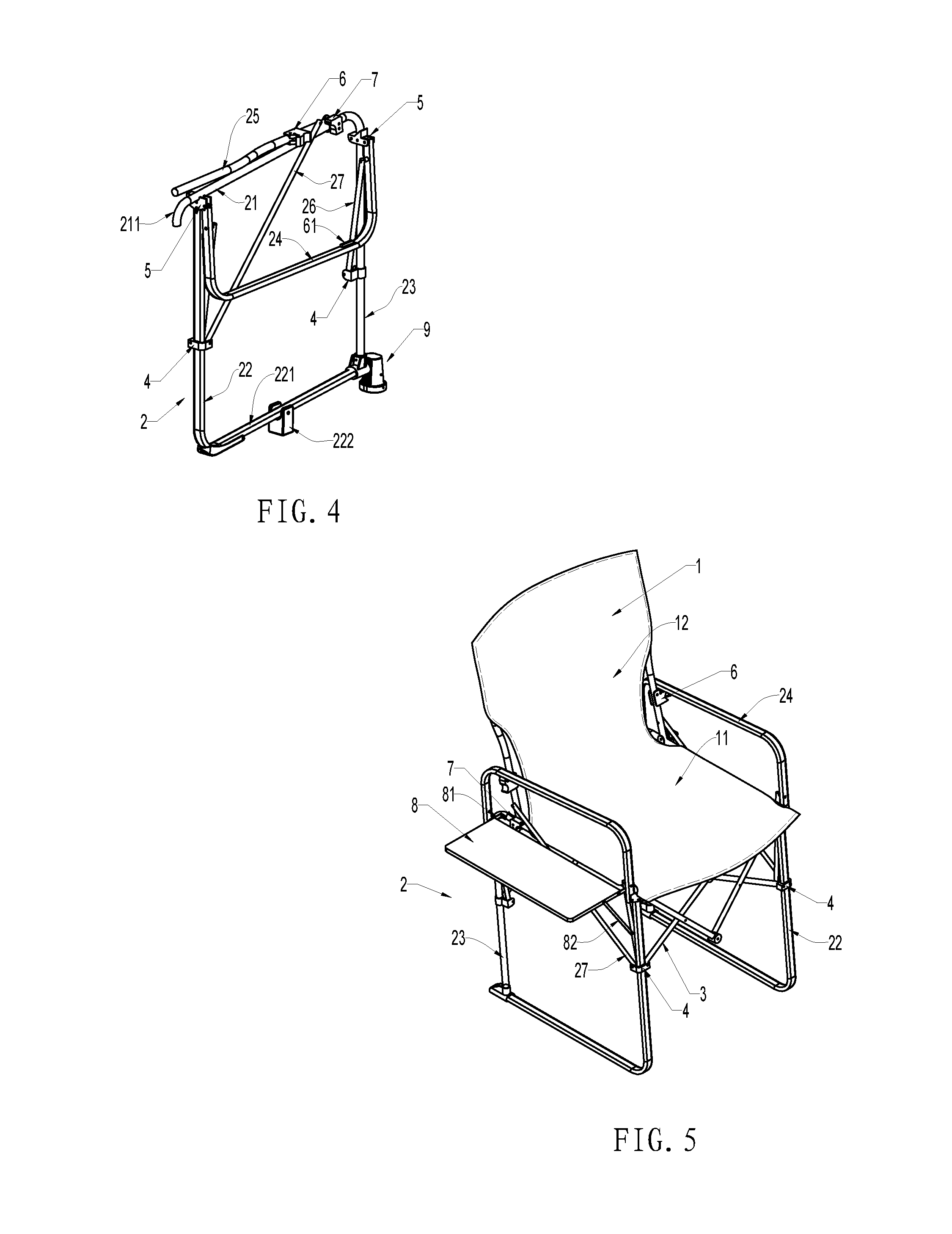
[0027] FIG. 4 is a schematic view of one side of the support section of the foldable director chair in folded position.
[0028] FIG. 5 is a schematic view of the foldable director chair with a tabletop.
[0029] FIG. 6 is a schematic view of the foldable frame of the foldable director chair with a tabletop.
[0030] FIG. 7 is a schematic view of one side of the support section with a tabletop in folded position.
[0031] FIG. 8 is a schematic view of the latch hook.
[0032] FIG. 9 is a cross-sectional view of the latch hook.
[0033] FIG. 10 is a decomposition view of the spring-loaded leg base.
[0034] Similar reference characters denote corresponding features consistently throughout the attached drawings. Namely, in the drawings the following reference numbers refer to the following parts: [0035] 1--seat fabric [0036] 11--seat area [0037] 12--backrest area [0038] 13--side pocket [0039] 2--support section [0040] 21--seat support bar [0041] 211--curved extension [0042] 22--front support bar [0043] 221--ground bar [0044] 222--plastic fulcrum [0045] 23--rear support bar [0046] 24--armrest bar [0047] 25--backrest bar [0048] 26--driving bar [0049] 27--drawbar [0050] 3--diagonal bar set [0051] 4--sliding component [0052] 5--fixed component [0053] 6--locking component [0054] 61--stopper [0055] 62--grooved opening [0056] 63--latch hook [0057] 64--circular operating area [0058] 65--spring component [0059] 7--position locker [0060] 8--tabletop [0061] 81--hinge piece [0062] 82--supporting piece [0063] 9--spring-loaded leg base [0064] 91--cylindrical housing [0065] 911--grooved track [0066] 92--bottom cap [0067] 93--spring [0068] 94--connecting component [0069] 941--leg sleeve [0070] 942--connecting bar [0071] 943--spring cap
DETAILED DESCRIPTION OF THE PREFERRED EMBODIMENT(S)
[0072] FIG. 1 shows a foldable director chair. It includes a folding frame, seat area 11 and backrest area 12. In this example, the seat area 11 and the backrest area 12 are formed with soft fabric. The fabric of the two areas are connected to create a one-piece seat fabric design 1. The backrest 12 is preferably in a trapezoid shape. The area where the backrest connects with the seat area is quite wide so that it completely covers the backrest bar and is more visually aesthetic.
[0073] Referring to FIG. 1 to FIG. 4, the folding frame includes a support section 2 on both sides in corresponding or symmetrical positions, a diagonal bar set 3 that connects the two support sections 2 on both sides. The diagonal bar set 3 drives the support sections 2 on both sides to perform the closing and folding actions. The support section 2 includes seat support bar 21, front support bar 22, rear support bar 23, armrest bar 24, and back support bar 25.
[0074] The seat support bar 21 and rear support bar 23 are formed by a L-shaped bar. The ground bar 221 is connected to the front support bar 22 at the bottom forming a L-shape. The upper portion of the aforementioned front support bar 22 is fixed on the seat support bar 21. The lower portion of the aforementioned rear support bar 23 is fixed on the ground bar 221. This allows the seat support bar 21 to create a rigid and rectangular-shaped support body with the front and rear support bars 22, 23.
[0075] Furthermore, a downward curved extension 211 is connected to the fixed area of the seat support bar 21 which extends pass the front end of the front support bar 22. This curved extension 211 is installed on the rear of the seat fabric, forming the front part of the circular structure. It is gives a heavy feeling while it can also partially cover the foldable frame. The aforementioned curved extension 211 can be directly formed by curving the front end of the seat support bar 21 as in the illustration. It may also be formed by using an elbow-shaped plastic component and locking it in place onto the end of the seat support bar 21.
[0076] A sliding component 4 is installed on both the aforementioned front support bar 22 and the rear support bar 23, and a fixed component 5 on the upper end. The armrest bar 24 is in an inverted U-shaped structure. The two ends are hinged at the above-mentioned fixed components 5. A driving bar 26 is hinged on each end of the armrest bar 24. The other end of the driving bar 26 is hinged on the sliding component 4 of the support bar located on the same side. When the armrest bar 24 is turned outward, it drives the sliding component 4 to slide downwardly along the support bar and is connected to the folding operation. The lower portion of the backrest bar 25 is hinged on the seat support bar 21. A drawbar 27 is hinged near its end. The other end of the drawbar 27 is hinged on the sliding component 4 on the front support bar 22. When the sliding component 4 slides downward, it draws the backrest bar 25 toward the front so that it rests on the backrest bar 21.
[0077] A locking component 6 is located on the junction of the aforementioned backrest bar 25 and armrest bar 24. A stopper 61 is installed on the armrest bar 24, so that the corresponding positions of the backrest bar 25 and the armrest bar 24 can be secured by the locking component 6, avoiding the armrest bar 24 being pushed outward by accident. There is a position locker 7 affixed on the hinge point of the seat support bar 21 and backrest bar 25. When the backrest bar 25 is opened to the desired position, this position locker 7 touches the drawbar 27 such that it restricts the reclining angle of the backrest bar 25 and reduces the pressure applied onto the locking component 6.
[0078] The aforementioned diagonal bar set 3 comprises the front diagonal and rear diagonal bar sets. The two ends of the front diagonal bar set 3 are hinged on the fixed component 5 and the sliding component 4 on the front support bar 22. The two ends of the rear diagonal bar set 3 are hinged on the fixed component 5 and the sliding component 4 on the rear support bar. The diagonal bar set 3 consists of two sets of diagonal bars that are crossed and hinged together at their central crossing point. These four connected bars form a foldable structure. As the sliding component 4 moves upwardly and downwardly, it achieves the opening and folding the support sections 2 on both sides. As illustrated in FIG. 4, when folding, the armrest bar 24 can be moved outward at an angle greater than 160 degrees, close to the outside of the front and rear support bars 22, 23. At the same time, the sliding component 4 is driven downward by the driving bar 26. When the drawbar 27 travels downward, the backrest bar 25 is further brought forward until it is in parallel with the seat support bar 21 to achieve folding.
[0079] Referring to FIG. 1 again, the aforementioned seat fabric 1 is secured to the seat support bar 21 and the backrest bar 25. It is held tightly by the seat support bars 21 and backrest bars 25 on the two sides to create a seat area. In addition, a side pocket 13 is located between the front support bar 22 and the rear support bar 23. The upper edge of this side pocket 13 is positioned higher than the seat area 11, forming a structure that encloses the seat area 11. This side pocket 13 uses a soft fabric similar to the seat fabric 1. It satisfies the utility need and does not affect the folding down of the armrest bar 24. There is optionally a cup bag and a storage bag on the side pocket 13 to provide storage space. This director chair is compact and gives a sense of enclosure. Of course, the following design option may also be considered.
[0080] Referring to FIGS. 5-7, this design has a foldable side table 8. The seat fabric 1 in the mid-section of the backrest area 12 has a waist cutout which is a design variation. The overall structure is similar to the above example. In this design, the folding tabletop 8 is hinged on the seat support bar 21 by two hinges 81. A supporting piece 82 is hinged onto the center of each side of the tabletop 8 in the front and back. The other end of the supporting piece 82 is hinged on the same side of the driving bar 26. When the driving bar 26 is moved downwardly, the tabletop 8 is pulled by the supporting piece 82 and folded on the side between the armrest bar 24 and the supporting piece, as shown in FIG. 7 when folded. The foldable tabletop 8 follows the director chair to achieve simultaneous opening and folding operations.
[0081] Referring to FIG. 8 and FIG. 9, this is a design with a preferred locking component. On one side of the locking component 6, there is a latch hook 63 on the top and a curved operating area 64 at the bottom. The other side is molded with a grooved opening 62. By placing this grooved opening 62 on the backrest bar 25 and hinging it onto the bar with a screw, it allows the locking component 6 to move properly. There is a spring component 65 located in the inner grooves of the grooved opening 62. This spring component 65 is in contact with the exterior of the backrest bar 25 to ensure the latch hook 63 is locking the stopper securely. The aforementioned spring 65 may be a torsion spring or like the spring shown in the illustrations.
[0082] Referring to FIG. 1 to FIG. 4 again, a fixed component is extended from the rear end of the ground bar 221 and the rear support bar 23. A spring-loaded leg base 9 is secured on the end of this fixed component. A plastic fulcrum 222 is installed in the front-center portion of the ground bar 221. The director chair can rock back and forth along this plastic fulcrum 222. In this design, the plastic fulcrum 222 should be positioned at the front-center of the center of gravity, and the preferred position is within 10 cm from the center of gravity.
[0083] Referring to FIG. 10, more specifically, the spring-loaded leg base 9 includes: a cylindrical housing 91 with grooved tracks, a bottom cap 92, a spring 93, and a connecting component 94. The spring 93 is placed inside the cylindrical housing 91 and held in place inside by the bottom cap 92. The connecting component 94 consists of a unified leg sleeve 941, a connecting bar 942, and a spring cap 943. The connecting bar 942 passes through the grooved tracks 911. The spring cap 943 is located inside the cylindrical housing 91 and placed on the top of the spring 93. The leg sleeve 941 is locked in position on one end of the ground bar 221, which also means the leg base is located at the rear end of the ground bar 221.
[0084] When a person's center of gravity crosses the plastic fulcrum 222, the spring 93 inside the spring-loaded leg base will be compressed, creating a flexible support. Combining the displacement of center of gravity by human motion and the rebounding force of the spring, the director chair can be easily rocked forward. This back and forth motion gives a regular director chair the rocking function.
* * * * *
D00000
D00001
D00002
D00003
D00004
D00005
XML
uspto.report is an independent third-party trademark research tool that is not affiliated, endorsed, or sponsored by the United States Patent and Trademark Office (USPTO) or any other governmental organization. The information provided by uspto.report is based on publicly available data at the time of writing and is intended for informational purposes only.
While we strive to provide accurate and up-to-date information, we do not guarantee the accuracy, completeness, reliability, or suitability of the information displayed on this site. The use of this site is at your own risk. Any reliance you place on such information is therefore strictly at your own risk.
All official trademark data, including owner information, should be verified by visiting the official USPTO website at www.uspto.gov. This site is not intended to replace professional legal advice and should not be used as a substitute for consulting with a legal professional who is knowledgeable about trademark law.