Spring-loaded Leg Base
Frankel; Andrew David ; et al.
U.S. patent application number 15/950219 was filed with the patent office on 2019-10-17 for spring-loaded leg base. This patent application is currently assigned to Zenithen USA LLC d/b/a Z Company, Zenithen USA LLC d/b/a Z Company. The applicant listed for this patent is Zenithen USA LLC d/b/a Z Company, Zenithen USA LLC d/b/a Z Company. Invention is credited to Andrew David Frankel, Shi-Ping Zheng, Tian-Xia Zheng.
| Application Number | 20190313797 15/950219 |
| Document ID | / |
| Family ID | 68160849 |
| Filed Date | 2019-10-17 |
| United States Patent Application | 20190313797 |
| Kind Code | A1 |
| Frankel; Andrew David ; et al. | October 17, 2019 |
SPRING-LOADED LEG BASE
Abstract
A type of spring-loaded leg base includes a base, a spring, and a connecting component. The base has a hollow chamber. The spring is placed inside the chamber. The connecting component is a unified component of a leg sleeve, a connecting bar and a spring cap. By passing the connecting bar through the grooved track and placing the spring cap on the top of the spring, the leg sleeve can be locked in position on the chair frame to create flexible support. This mechanism creates the rocking function for a regular chair.
| Inventors: | Frankel; Andrew David; (Yorba Linda, CA) ; Zheng; Shi-Ping; (Fuzhou, CN) ; Zheng; Tian-Xia; (Fuzhou, Fujian, CN) | ||||||||||
| Applicant: |
|
||||||||||
|---|---|---|---|---|---|---|---|---|---|---|---|
| Assignee: | Zenithen USA LLC d/b/a Z
Company |
||||||||||
| Family ID: | 68160849 | ||||||||||
| Appl. No.: | 15/950219 | ||||||||||
| Filed: | April 11, 2018 |
| Current U.S. Class: | 1/1 |
| Current CPC Class: | A47C 7/002 20130101; A47C 3/02 20130101 |
| International Class: | A47C 3/02 20060101 A47C003/02; A47C 7/00 20060101 A47C007/00 |
Claims
1. A spring-loaded leg base comprising: A base having a hollow chamber inside; A grooved track installed on the wall of the chamber, wherein the grooved track is parallel to the central axis of the inner chamber; The spring placed inside the chamber of the base; A connecting component having a leg sleeve, a connecting bar, and a spring cap forming a one-piece structure, wherein said spring cap is placed inside the chamber of the base and on top of the spring and the connecting bar passes through the grooved track and the leg sleeve can be locked in position on the chair frame to create flexible support.
2. The spring-loaded leg base of claim 1, wherein the base is a separate structure including a base and a cylindrical housing; The perimeter of the base bottom is molded with an enclosing sleeve; The center is molded with a protruding console; The cylindrical housing is molded with a chamber that has an opening and a grooved track; The lower part of the spring cap is set on the protruding console to maintain a centralized structure; After the connecting bar of the connecting component is placed in the grooved track of the cylindrical housing, the cylindrical housing is inverted and tied to the top of the spring; and The lower part of the cylindrical housing is mounted inside the enclosing sleeve of the base bottom and secured by a screw.
3. The spring-loaded leg base of claim 2, wherein the spring is a conical spring; The chamber of the cylindrical housing is in a corresponding conical structure; and There is a gap between the mid-upper part of the chamber and the spring that allows spring movements.
4. The spring-loaded leg base of claim 2, wherein the spring cap of the connecting bar is molded with an inverted concave cavity, which is used for buckling at the top of the spring.
5. The spring-loaded leg base of claim 2, wherein on the cylindrical housing, both sides of the grooved track are equipped with guiding lips that protrude outwardly.
Description
BACKGROUND OF THE INVENTION
Field of the Invention
[0001] The present invention relates to a chair accessory, and more particularly to a type of spring-loaded leg base. The base is placed where the chair frame touches the ground so that the chair can rock properly.
Technical Background
[0002] A rocking chair is a common leisure facility that has a rocking feature. However, it typically relies on arched bar components to have contact with the ground to create rocking movements. This causes the chair to remain in an unstable condition all the time, limiting its use to only certain leisure occasions. As such, manufacturers have improved on its defect, so that rocking chairs can work in a stable mode and a rocking mode.
[0003] For example, a collapsible and portable rocking chair disclosed in Published U.S. Patent Application Publication U.S.20150282625A1. It includes an expandable and collapsible seat frame. That seat frame consists of a pair of side frame components and a connecting bar that connect the two side frames, and it is supported by the backrest support component and the seat cushion support bar that correspondingly support the soft backrest and seat cushion.
[0004] A pair of side frame components, which include a front support leg component, a rear support leg component, and a pivot point component. The pivot point component is located at the center-rear area of the side frame, using the ground surface for support, so that the chair can move back and forth along the pivot point.
[0005] At least one rocker mechanism is connected to each side frame component to provide support for the aforementioned chair during its back and forth movements.
[0006] The aforementioned rocker mechanism comprises a cylindrical housing, a spring and a tubular component, which is essentially a spring-loaded retractable bar or a standard air spring component. The overall length is rather long. Therefore, the upper portion is mounted on the joint between the rear leg component and the backrest support, and the lower portion is mounted on the gliding rail that touches the ground in order to perform rocking movements.
[0007] The description also gives an example of an alternate rocker mechanism design which comprises only a cylindrical housing with a spring inside it. The rocking chair's front leg component and rear leg component are connected to the spring directly, leveraging the lower end of the leg components and the cylindrical housing to create the retractable function. But this mechanism is difficult to achieve in reality. When the chair leg components rock back and forth along the pivot point in arc-shaped movements, the angle of the leg components is still changing constantly. Also, because the bottom part of the sleeve housing that touches the ground is constrained by the ground, it is unable to follow the angle of the leg components to make timely changes. This causes the lower end of the leg components to be stuck inside the sleeve housing and unable to function normally, so that either the rocking function is lost or the rocking movement is not smooth.
[0008] The present invention aims to offer a type of spring-loaded leg base that can be used with any type of chair to achieve the rocking function.
SUMMARY OF THE INVENTION
[0009] One goal of this invention is to provide an improved design for a spring-loaded leg base. In one embodiment, it comprises a type of spring that is placed inside a base chamber and is connected to the chair frame and spring via the connecting components that pass through the base grooved tracks.
[0010] The technical plan of this invention was completed in the following manner:
[0011] A type of spring-loaded leg base with the following characteristics:
[0012] The base having a hollow chamber inside. A grooved track is installed on the wall of the chamber. The grooved track is parallel to the central axis of the inner chamber.
[0013] A spring placed inside the chamber of the base.
[0014] A connecting component having a leg sleeve, a connecting bar, and a spring cap. These three parts together form a one-piece structure. The spring cap is placed inside the chamber of the base and on top of the spring. The connecting bar passes through the grooved track. The leg sleeve can be locked in position on the chair frame to create flexible support.
[0015] The aforementioned base is a separate structure that includes a base and a cylindrical housing. The perimeter of the base bottom is molded with an enclosing sleeve. The center is molded with a protruding console. The cylindrical housing is molded with a chamber that has an opening and a grooved track. The lower part of the spring cap is set on the protruding console to maintain a centralized structure. After the connecting bar of the connecting component is placed in the grooved track of the cylindrical housing, the cylindrical housing is inverted and tied to the top of the spring. The lower part of the cylindrical housing is mounted inside the enclosing sleeve of the base bottom and secured by a screw.
[0016] The aforementioned spring is preferably a conical spring. The chamber of the cylindrical housing is in a corresponding conical structure. There is a gap between the mid-upper part of the chamber and the spring that allows spring movements.
[0017] The aforementioned spring cap of the connecting bar is molded with an inverted concave cavity, which is used for buckling onto the top of the spring.
[0018] On the aforementioned cylindrical housing, both sides of the grooved track are equipped with guiding lips that protrude outward.
[0019] This invention skillfully utilizes a grooved track design on the base. By means of a connecting component that passes through the grooved track, it connects the seat frame and the spring. The gap between the base chamber and the connecting component's spring and spring cap automatically adapts to the changing angles when the chair is rocking. Specifically, the conical spring has the ability to automatically position itself in the center and to guide itself. This ability is appropriately utilized here.
BRIEF DESCRIPTION OF THE DRAWINGS
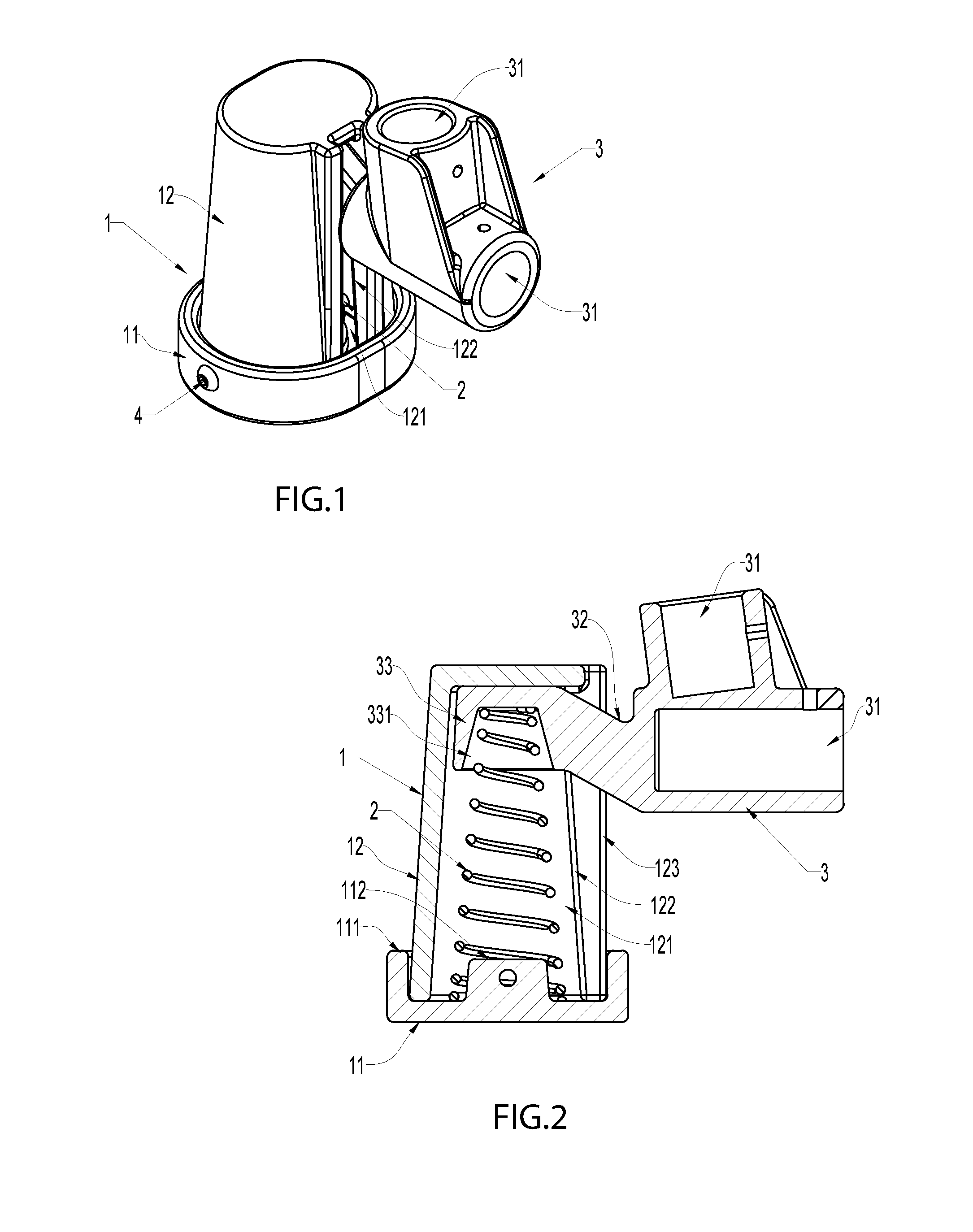
[0020] FIG. 1 is a perspective view of the spring-loaded leg base.
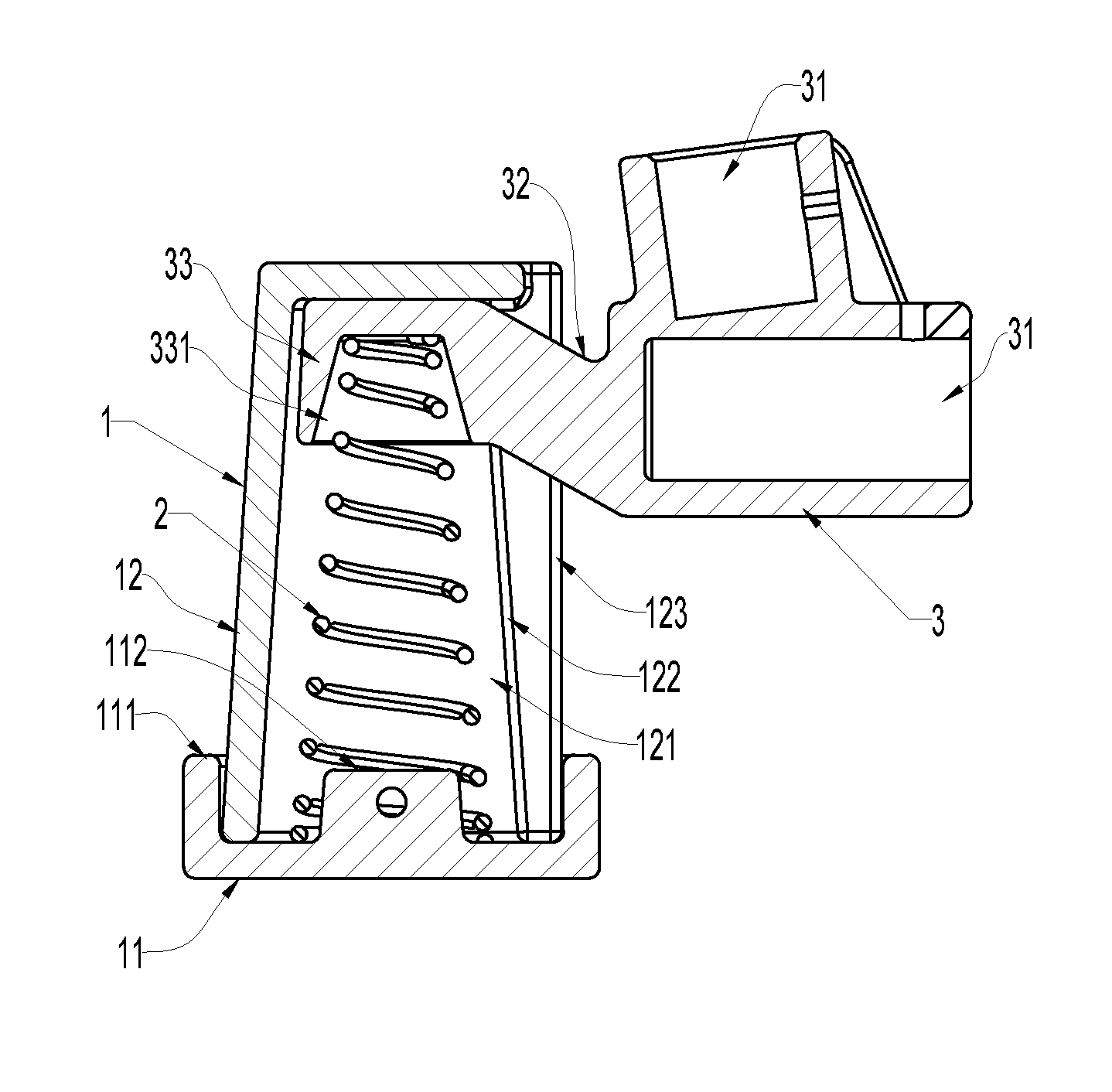
[0021] FIG. 2 is a cross-sectional view of the spring-loaded leg base.
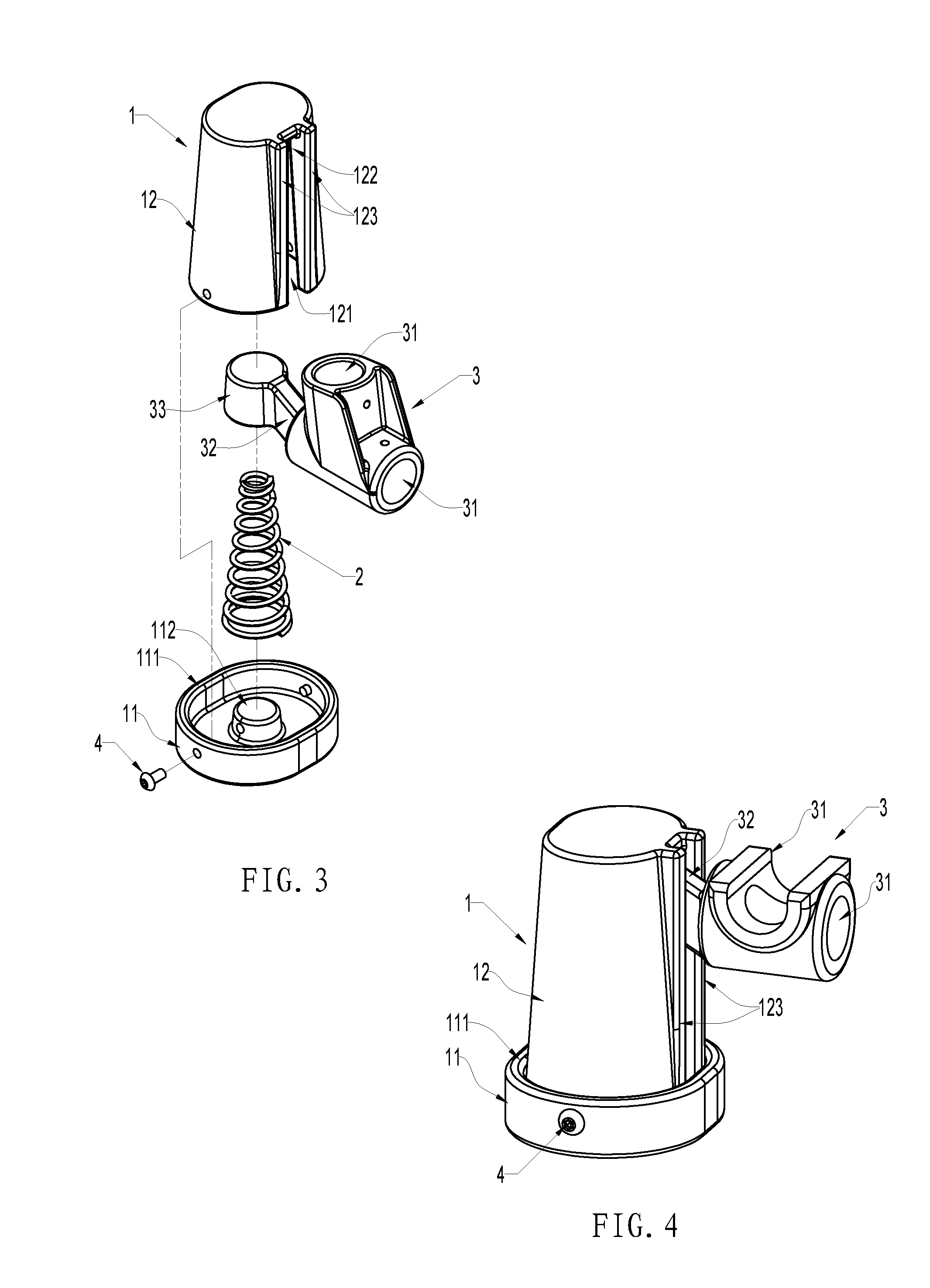
[0022] FIG. 3 is a decomposition ("exploded") view of the spring-loaded leg base.
[0023] FIG. 4 is a perspective view of an alternate embodiment of the spring-loaded leg base.
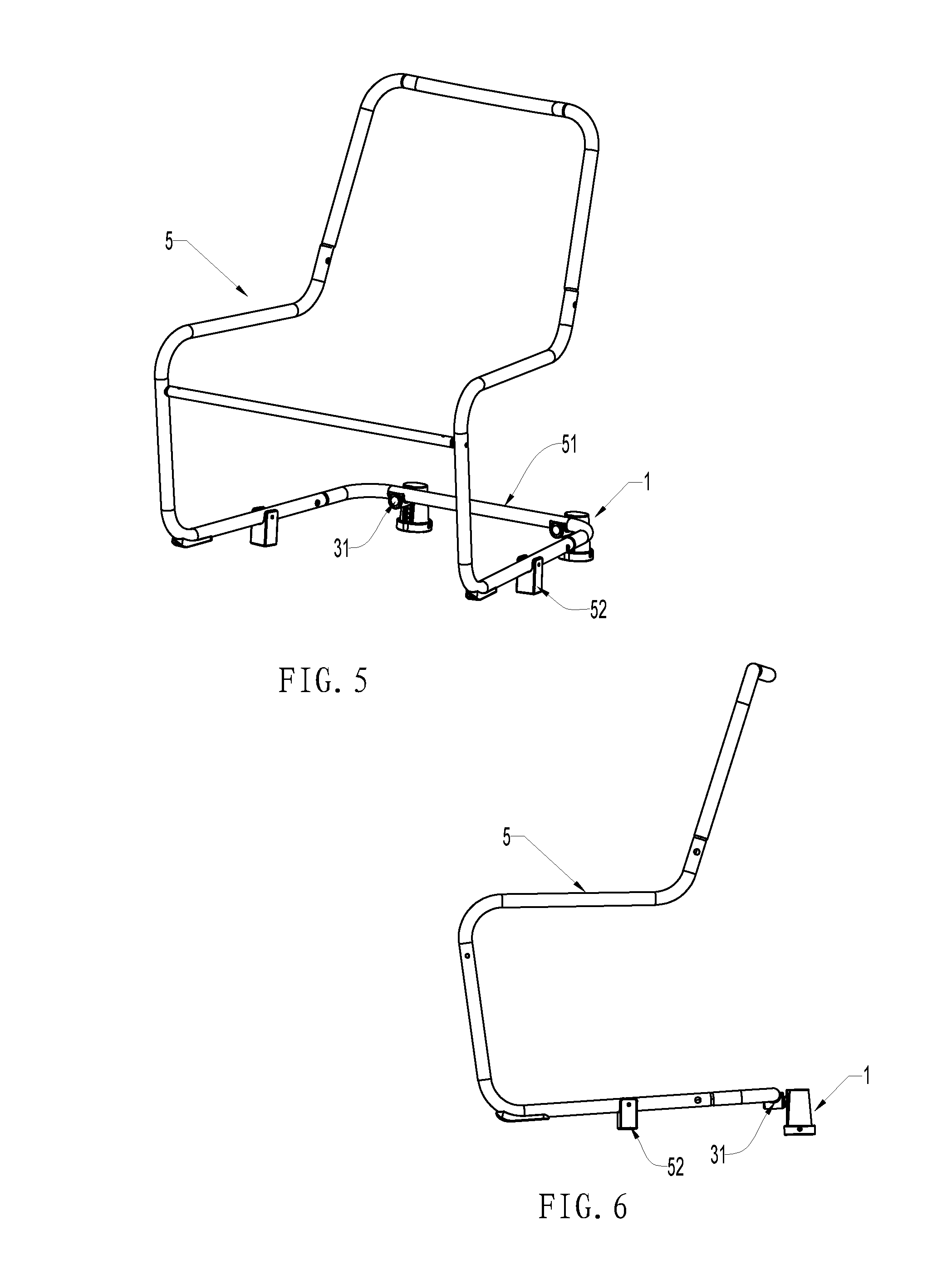
[0024] FIG. 5 is a perspective view of the chair frame.
[0025] FIG. 6 is a side-view of the chair frame.
[0026] Similar reference characters denote corresponding features consistently throughout the attached drawings. Namely, in the drawings the following reference numbers refer to the following part: [0027] 1--Base [0028] 11--Base bottom [0029] 111--Enclosing sleeve [0030] 112--Protruding console [0031] 12--Cylindrical housing [0032] 121--Chamber [0033] 122--Grooved track [0034] 123--Guiding lips [0035] 2--Spring [0036] 3--Connecting component [0037] 31--Leg sleeve [0038] 32--Connecting bar [0039] 33--Spring cap [0040] 331--Inverted concave cavity [0041] 4--Screw [0042] 5--Chair frame [0043] 51--Horizontal connecting bar [0044] 52--Pivot point
DETAILED DESCRIPTION OF THE PREFERRED EMBODIMENT(S)
[0045] Referring to FIGS. 1-3, a type of spring-loaded leg base is shown including a base 1, a spring 2, and a connecting component 3.
[0046] Base 1 has a chamber with a hollow structure. Specifically, base 1 is a separate structure which includes two parts: a base bottom 11 and a cylindrical housing 12. The perimeter of the base bottom 11 is molded with an enclosing sleeve 111. The center is molded with a protruding console 112. The cylindrical housing 12 is molded with a chamber 121 that has an opening and a grooved track 122. The grooved track 122 is parallel to the central axis of the chamber 121. On the two sides of the grooved track 122, there are guiding lips 123 that protrude outwardly. The lower part of the cylindrical housing 12 is mounted inside the enclosing sleeve 111 of the base bottom 11 and secured by a screw 4 or other fastener. Of course, an alternative option is for the base 11 to be on top, the cylindrical housing 12 at the bottom, and the cylindrical housing 12 to contact the ground. The top is covered with base 11. However, this configuration makes it difficult to produce a conical chamber.
[0047] The spring 2 is placed inside the chamber 121 of the base 1. It can be compressed and expanded along the central axis of the chamber.
[0048] The connecting component 3 has a leg sleeve 31, a connecting bar 32, and a spring cap 33. These three parts together form a one-piece structure. The spring cap 33 is placed inside the chamber of the base 11 and on the top of the spring 2. The connecting bar 32 passes through the grooved track 122. The leg sleeve 31 can be locked in position on the chair frame to create flexible support. With this design, two leg sleeves 31 can be set at an approximately horizontal position and an approximately vertical position, so that they connect with the horizontal end or vertical end of the component at the lower part of the chair frame.
[0049] During installation, the lower part of the spring 2 is set on the protruding console 112 of the base to maintain a centralized structure. After the connecting bar 32 of the connecting component 3 is placed in the grooved track 122 of the cylindrical housing, the cylindrical housing 12 is inverted and tied to the top of the spring 2. The lower part of the cylindrical housing 12 is mounted inside the enclosing sleeve 111 of the base bottom and secured by a screw 4. This forms the spring-loaded leg base unit.
[0050] Furthermore, the aforementioned spring 2 is a conical spring. The chamber of the cylindrical housing 12 is in a corresponding conical structure. Between the mid-upper part of the chamber 121 and the spring 2, there is at least some gap that allows swinging movements of the spring 2. In addition, the spring cap 33 of the connecting bar is molded with an inverted concave cavity 331. This inverted concave cavity 331 is used for buckling onto the top of the spring 2, forming an installation structure. The inherent tension of the spring 2 keeps the spring cap 33 in contact with the top of the chamber 121 and bears the weight of the chair. Another benefit of using a conical spring is that it can create a nested form of compression so that the height after compression can be further lowered, allowing a bigger rocking magnitude under the same condition. The aforementioned spring cap 33 and the chamber 121 maintains a gap that allows reasonable movements of the spring cap 33 without being locked in a fixed position.
[0051] As shown in FIG. 4, the two leg sleeves 31 of the connecting component in this illustration are in an approximately orthogonal position. This is particularly suitable for mounting onto the connecting bar on the rear side of the chair frame.
[0052] Referring to FIG. 5 and FIG. 6, illustrations of the spring-loaded leg base in use. The chair frame 5 has a connecting bar 51 on its rear side. Each of the two spring-loaded leg bases is locked in place on the connecting cross bar 51 by means of a leg sleeve 31. By setting a pivot point 52 at the mid-front area of both sides of the chair frame, the chair can rock back and forth along that pivot point 52. When rocking backward, the spring inside the spring-loaded leg base will be compressed, creating flexible support. Combining the human center of gravity factor and the rebounding force of the spring, the chair can be easily rocked forward. With this, a regular chair may be used to perform rocking function.
* * * * *
D00000
D00001
D00002
D00003
XML
uspto.report is an independent third-party trademark research tool that is not affiliated, endorsed, or sponsored by the United States Patent and Trademark Office (USPTO) or any other governmental organization. The information provided by uspto.report is based on publicly available data at the time of writing and is intended for informational purposes only.
While we strive to provide accurate and up-to-date information, we do not guarantee the accuracy, completeness, reliability, or suitability of the information displayed on this site. The use of this site is at your own risk. Any reliance you place on such information is therefore strictly at your own risk.
All official trademark data, including owner information, should be verified by visiting the official USPTO website at www.uspto.gov. This site is not intended to replace professional legal advice and should not be used as a substitute for consulting with a legal professional who is knowledgeable about trademark law.