Handling QoS Flow without a Mapping Data Radio Bearer
Huang-Fu; Chia-Chun ; et al.
U.S. patent application number 16/373895 was filed with the patent office on 2019-10-10 for handling qos flow without a mapping data radio bearer. The applicant listed for this patent is MEDIATEK INC.. Invention is credited to Chi-Hsien Chen, Chia-Chun Huang-Fu, Shang-Ru Mo.
| Application Number | 20190313262 16/373895 |
| Document ID | / |
| Family ID | 68096634 |
| Filed Date | 2019-10-10 |


| United States Patent Application | 20190313262 |
| Kind Code | A1 |
| Huang-Fu; Chia-Chun ; et al. | October 10, 2019 |
Handling QoS Flow without a Mapping Data Radio Bearer
Abstract
A PDU session and QoS flow handling mechanism is proposed when a QoS flow of a PDU session does not have a mapping DRB after a handover or a service request procedure. If the QoS flow is associated with a default QoS rule, the UE can locally release the PDU session, initiate a PDU session release procedure, send a 5GSM status message with proper cause, or assume the PDU session is not reactivated. On the other hand, if the QoS flow is not associated with a default QoS rule, the UE can locally delete the QoS flow, delete the QoS flow by using a PDU session modification procedure, or send a 5GSM status message with proper cause.
| Inventors: | Huang-Fu; Chia-Chun; (Hsin-Chu, TW) ; Chen; Chi-Hsien; (Hsin-Chu, TW) ; Mo; Shang-Ru; (Hsin-Chu, TW) | ||||||||||
| Applicant: |
|
||||||||||
|---|---|---|---|---|---|---|---|---|---|---|---|
| Family ID: | 68096634 | ||||||||||
| Appl. No.: | 16/373895 | ||||||||||
| Filed: | April 3, 2019 |
Related U.S. Patent Documents
| Application Number | Filing Date | Patent Number | ||
|---|---|---|---|---|
| 62655137 | Apr 9, 2018 | |||
| Current U.S. Class: | 1/1 |
| Current CPC Class: | H04L 67/141 20130101; H04L 69/22 20130101; H04W 60/06 20130101; H04W 24/02 20130101; H04W 36/0033 20130101; H04L 47/2441 20130101; H04W 36/0011 20130101; H04W 36/0022 20130101; H04W 28/0268 20130101; H04L 67/143 20130101; H04W 28/24 20130101; H04W 76/38 20180201; H04W 84/042 20130101; H04W 88/02 20130101; H04L 47/6295 20130101; H04W 36/14 20130101; H04L 47/2491 20130101 |
| International Class: | H04W 24/02 20060101 H04W024/02; H04L 29/08 20060101 H04L029/08 |
Claims
1. A method, comprising: receiving a radio resource control (RRC) reconfiguration by a user equipment (UE) in a mobile communication network, wherein the UE is configured with one or more Protocol data unit (PDU) sessions, and wherein an activated PDU session is configured with one or more QoS flows; detecting that a QoS flow of the activated PDU session has no mapping data radio bearer (DRB) available based on the RRC reconfiguration; performing a first PDU session and QoS flow handling when the QoS flow is associated with a default QoS rule; and performing a second PDU session and QoS flow handing when the QoS flow is not associated with the default QoS rule.
2. The method of claim 1, wherein the RRC reconfiguration is due to an intra-system or inter-system handover procedure.
3. The method of claim 1, wherein RRC reconfiguration is due to a UE-initiated or a network-initiated service request procedure.
4. The method of claim 1, wherein the first PDU session and QOS handling involves releasing the activated PDU session locally by the UE.
5. The method of claim 1, wherein the first PDU session and QoS flow handling involves initiating a PDU session release procedure with the network.
6. The method of claim 1, wherein the first PDU session and QoS flow handling involves the UE treating the activated PDU session as not reactivated.
7. The method of claim 1, wherein the second PDU session and QoS flow handling involves deleting the QoS flow locally by the UE or explicitly by using a PDU session modification procedure.
8. The method of claim 1, wherein the second PDU session and QoS flow handling involves the UE treating the QoS flow as not reactivated.
9. The method of claim 1, wherein the UE detects that the QoS flow is mapped to a DRB but the DRB is not established after the RRC reconfiguration.
10. The method of claim 1, wherein the UE detects that a mapping between the QoS flow and any established DRB is missing and there is no default DRB available after the RRC reconfiguration.
11. A User Equipment (UE), comprising: a receiver that receives a radio resource control (RRC) reconfiguration in a mobile communication network, wherein the UE is configured with one or more Protocol data unit (PDU) sessions, and wherein an activated PDU session is configured with one or more QoS flows; a configure and control circuit that detects that a QoS flow of the activated PDU session has no mapping data radio bearer (DRB) available based on the RRC reconfiguration; and a QoS flow handling circuit that performs a first PDU session and QoS flow handling when the QoS flow is associated with a default QoS rule, otherwise performing a second PDU session and QoS flow handing when the QoS flow is not associated with the default QoS rule.
12. The UE of claim 11, wherein the RRC reconfiguration is due to an intra-system or inter-system handover procedure.
13. The UE of claim 11, wherein RRC reconfiguration is due to a UE-initiated or a network-initiated service request procedure.
14. The UE of claim 11, wherein the first PDU session and QOS handling involves releasing the activated PDU session locally by the UE.
15. The UE of claim 11, wherein the first PDU session and QoS flow handling involves initiating a PDU session release procedure with the network.
16. The UE of claim 11, wherein the first PDU session and QoS flow handling involves the UE treating the activated PDU session as not reactivated.
17. The UE of claim 11, wherein the second PDU session and QoS flow handling involves deleting the QoS flow locally by the UE or explicitly by using a PDU session modification procedure.
18. The UE of claim 11, wherein the second PDU session and QoS flow handling involves the UE treating the QoS flow as not reactivated.
19. The UE of claim 11, wherein the UE detects that the QoS flow is mapped to a DRB but the DRB is not established after the RRC reconfiguration.
20. The UE of claim 11, wherein the UE detects that a mapping between the QoS flow and any established DRB is missing and there is no default DRB available after the RRC reconfiguration.
Description
CROSS REFERENCE TO RELATED APPLICATIONS
[0001] This application claims priority under 35 U.S.C. .sctn. 119 from U.S. Provisional Application No. 62/655,137, entitled "5GSM Enhancement on Interworking", filed on Apr. 9, 2018, the subject matter of which is incorporated herein by reference.
TECHNICAL FIELD
[0002] The disclosed embodiments relate generally to wireless communication, and, more particularly, to method of handling Quality of Service (QoS) flows without a mapping data radio bearer (DRB) in 5G new radio (NR) systems.
BACKGROUND
[0003] The wireless communications network has grown exponentially over the years. A Long-Term Evolution (LTE) system offers high peak data rates, low latency, improved system capacity, and low operating cost resulting from simplified network architecture. LTE systems, also known as the 4G system, also provide seamless integration to older wireless network, such as GSM, CDMA and Universal Mobile Telecommunication System (UMTS). In LTE systems, an evolved universal terrestrial radio access network (E-UTRAN) includes a plurality of evolved Node-Bs (eNodeBs or eNBs) communicating with a plurality of mobile stations, referred to as user equipments (UEs). The 3.sup.rd generation partner project (3GPP) network normally includes a hybrid of 2G/3G/4G systems. The Next Generation Mobile Network (NGMN) board, has decided to focus the future NGMN activities on defining the end-to-end requirements for 5G new radio (NR) systems.
[0004] In 5G, a Protocol Data Unit (PDU) session establishment is a parallel procedure of a Packet Data Network (PDN) connection procedure in 4G. A PDU session defines the association between the UE and the data network that provides a PDU connectivity service. Each PDU session is identified by a PDU session ID, and may include multiple QoS flows and QoS rules. In 5G network, QoS flow is the finest granularity for QoS management to enable more flexible QoS control. The concept of QoS flow in 5G is like EPS bearer in 4G. Each QoS flow is identified by a QoS flow ID (QFI) which is unique within a PDU session. Each QoS rule is identified by a QoS rule ID (QRI). There can be more than one QoS rule associated with the same QoS flow. A default QoS rule is required to be sent to the UE for every PDU session establishment and it is associated with a QoS flow.
[0005] Each QoS flow needs to be supported by a mapping Data Radio Bearer (DRB) in Access Stratum (AS) layer. Multiple QoS flows can be mapped to the same DRB. If there is a default DRB for a PDU session, then all traffic of QoS flows that have no mapping DRBs are sent via the default DRB. After an intra-system or inter-system handover procedure, or after a UE-initiated or network-initiated service request procedure, the RRC/AS layer may indicate that a QoS flow is not supported, e.g., the mapping DRB for the QoS flow is not established, or the mapping for the QoS flow to a DRB is missing and there is no default DRB available.
[0006] A solution is sought to properly handle PDU session and QoS flow management when UE cannot find a mapping DRB for a QoS flow of a PDU session after a handover procedure or a service request procedure.
SUMMARY
[0007] A PDU session and QoS flow handling mechanism is proposed when a QoS flow of a PDU session does not have a mapping DRB after a handover or a service request procedure. If the QoS flow is associated with a default QoS rule, then all QoS flows of the PDU session is impacted and corresponding action is thus required for the PDU session. Specifically, the UE can locally release the PDU session, initiate a PDU session release procedure, send a 5GSM status message with proper cause, or assume the PDU session is not reactivated. On the other hand, if the QoS flow is not associated with a default QoS rule, then only this particular QoS flow is impacted and corresponding action is thus required for the QoS flow. Specifically, the UE can locally delete the QoS flow, delete the QoS flow by using a PDU session modification procedure, or send a 5GSM status message with proper cause.
[0008] In one embodiment, a UE receives a radio resource control (RRC) reconfiguration in a mobile communication network. The UE is configured with one or more Protocol data unit (PDU) sessions, and an activated PDU session is configured with one or more QoS flows. The UE detects that a QoS flow of the activated PDU session has no mapping data radio bearer (DRB) available based on the RRC reconfiguration. The UE performs a first PDU session and QoS flow handling when the QoS flow is associated with a default QoS rule. The UE performs a second PDU session and QoS flow handing when the QoS flow is not associated with the default QoS rule. In one embodiment, the UE locally releases the PDU session, initiates a PDU session release procedure, sends a 5GSM status message with proper cause, or assumes the PDU session is not reactivated when the QoS flow is associated with the default QoS rule. In another embodiment, the UE locally deletes the QoS flow, deletes the QoS flow by using a PDU session modification procedure, or sends a 5GSM status message with proper cause when the QoS flow is not associated with the default QoS rule.
[0009] Other embodiments and advantages are described in the detailed description below. This summary does not purport to define the invention. The invention is defined by the claims.
BRIEF DESCRIPTION OF THE DRAWINGS
[0010] The accompanying drawings, where like numerals indicate like components, illustrate embodiments of the invention.
[0011] FIG. 1 illustrates an exemplary 5G network supporting Quality of Service (QoS) rule management after receiving radio resource control (RRC) reconfiguration in accordance with one novel aspect.
[0012] FIG. 2 illustrates simplified block diagrams of a user equipment (UE) in accordance with embodiments of the current invention.
[0013] FIG. 3 illustrates a first embodiment of PDU session and QoS flow handling after a handover procedure in accordance with one novel aspects.
[0014] FIG. 4 illustrates a flow chart of a novel PDU session and QoS flow handling when a QoS flow has no mapping DRB after a PDU session is reactivated.
[0015] FIG. 5 illustrates a second embodiment of PDU session and QoS flow handling after a UE-initiated service request procedure in accordance with one novel aspects.
[0016] FIG. 6 illustrates a third embodiment of PDU session and QoS flow handling after a network-initiated service request procedure in accordance with one novel aspects.
[0017] FIG. 7 is a flow chart of a method of PDU session and QoS flow handling in accordance with one novel aspect of the present invention.
DETAILED DESCRIPTION
[0018] Reference will now be made in detail to some embodiments of the invention, examples of which are illustrated in the accompanying drawings.
[0019] FIG. 1 illustrates an exemplary 5G network 100 supporting Quality of Service (QoS) rule management after receiving radio resource control (RRC) reconfiguration in accordance with one novel aspect. 5G new radio (NR) network 100 comprises a user equipment UE 101, a base station gNB 102, an access and mobility management function (AMF) 103, and a 5G core network 5GC 104. In the example of FIG. 1, UE 101 and its serving base station gNB 102 belong to part of a radio access network RAN 120. In Access Stratum (AS) layer, RAN 120 provides radio access for UE 101 via a radio access technology (RAT). In Non-Access Stratum (NAS) layer, AMF 103 communicates with gNB 102 and 5GC 104 for access and mobility management of wireless access devices in 5G network 100. UE 101 may be equipped with a radio frequency (RF) transceiver or multiple RF transceivers for different application services via different RATs/CNs. UE 114 may be a smart phone, a wearable device, an Internet of Things (IoT) device, and a tablet, etc.
[0020] 5GS networks are packet-switched (PS) Internet Protocol (IP) networks. This means that the networks deliver all data traffic in IP packets, and provide users with Always-On IP Connectivity. When UE joins a 5GS network, a Packet Data Network (PDN) address (i.e., the one that can be used on the PDN) is assigned to the UE for its connection to the PDN. In 4G, EPS has defined a Default EPS Bearer to provide the IP Connectivity that is Always-On. In 5G, a Protocol Data Unit (PDU) session establishment procedure is a parallel procedure of a PDN connection procedure in 4G. A PDU session defines the association between the UE and the data network that provides a PDU connectivity service. Each PDU session is identified by a PDU session ID, and may include multiple QoS flows and QoS rules. In 5G network, QoS flow is the finest granularity for QoS management to enable more flexible QoS control. The concept of QoS flow in 5G is like EPS bearer in 4G. Each QoS flow is identified by a QoS flow ID (QFI) which is unique within a PDU session. Each QoS rule is identified by a QoS rule ID (QRI). There can be more than one QoS rule associated with the same QoS flow. A default QoS rule is required to be sent to the UE for every PDU session establishment and it is associated with a QoS flow.
[0021] In the example of FIG. 1, UE 101 establishes a PDU session 110, which includes multiple QoS flows and QoS rules in Non-Access Stratum (NAS) layer. Each QoS flow needs to be supported by a mapping Data Radio Bearer (DRB) in Access Stratum (AS) layer. Multiple QoS flows can be mapped to the same DRB. For example, QoS flows #1 and #2 are mapped to DRB #1, and QoS flow #3 is mapped to DRB #2. If there is a default DRB for a PDU session, then all traffic of QoS flows that have no mapping DRBs are sent via the default DRB. However, a PDU session may not always have a default DRB. In addition, after an intra-system or inter-system handover procedure, or after a UE-initiated or network-initiated service request procedure, which triggers the PDU session being reactivated, the RRC/AS layer may indicate that a QoS flow is not supported by a mapping DRB, e.g., the mapping DRB for the QoS flow is not established, or the mapping for the QoS flow to a DRB is missing and there is no default DRB available.
[0022] In accordance with one novel aspect, a PDU session and QoS flow handling mechanism is proposed when a QoS flow of a PDU session does not have a mapping DRB after a handover or a service request procedure. If the QoS flow is associated with a default QoS rule, then all QoS flows of the PDU session is impacted and corresponding action is thus required for the PDU session. Specifically, the UE can locally release the PDU session, initiate a PDU session release procedure, send a 5GSM status message with proper cause, or assume the PDU session is not reactivated. On the other hand, if the QoS flow is not associated with a default QoS rule, then only this particular QoS flow is impacted and corresponding action is thus required for the QoS flow. Specifically, the UE can locally delete the QoS flow, delete the QoS flow by using a PDU session modification procedure, or send a 5GSM status message with proper cause.
[0023] FIG. 2 illustrates simplified block diagrams of wireless devices, e.g., a UE 201 and network entity 211 in accordance with embodiments of the current invention. Network entity 211 may be a base station combined with an MME or AMF. Network entity 211 has an antenna 215, which transmits and receives radio signals. A radio frequency RF transceiver module 214, coupled with the antenna, receives RF signals from antenna 215, converts them to baseband signals and sends them to processor 213. RF transceiver 214 also converts received baseband signals from processor 213, converts them to RF signals, and sends out to antenna 215. Processor 213 processes the received baseband signals and invokes different functional modules to perform features in base station 211. Memory 212 stores program instructions and data 220 to control the operations of base station 211. In the example of FIG. 2, network entity 211 also includes protocol stack 280 and a set of control functional modules and circuit 290. PDU session handling circuit 231 handles PDU session establishment and modification procedures. QoS flow and rule management circuit 232 creates, modifies, and deletes QoS flows and QoS rules for UE. Configuration and control circuit 233 provides different parameters to configure and control UE of related functionalities including mobility management and session management.
[0024] Similarly, UE 201 has memory 202, a processor 203, and radio frequency (RF) transceiver module 204. RF transceiver 204 is coupled with antenna 205, receives RF signals from antenna 205, converts them to baseband signals, and sends them to processor 203. RF transceiver 204 also converts received baseband signals from processor 203, converts them to RF signals, and sends out to antenna 205. Processor 203 processes the received baseband signals and invokes different functional modules and circuits to perform features in UE 201. Memory 202 stores data and program instructions 210 to be executed by the processor to control the operations of UE 201. Suitable processors include, by way of example, a special purpose processor, a digital signal processor (DSP), a plurality of micro-processors, one or more micro-processor associated with a DSP core, a controller, a microcontroller, application specific integrated circuits (ASICs), file programmable gate array (FPGA) circuits, and other type of integrated circuits (ICs), and/or state machines. A processor in associated with software may be used to implement and configure features of UE 201.
[0025] UE 201 also comprises a set of functional modules and control circuits to carry out functional tasks of UE 201. Protocol stacks 260 comprise Non-Access-Stratum (NAS) layer to communicate with an AMF entity connecting to the core network, Radio Resource Control (RRC) layer for high layer configuration and control, Packet Data Convergence Protocol/Radio Link Control (PDCP/RLC) layer, Media Access Control (MAC) layer, and Physical (PHY) layer. System modules and circuits 270 may be implemented and configured by software, firmware, hardware, and/or combination thereof. The function modules and circuits, when executed by the processors via program instructions contained in the memory, interwork with each other to allow UE 201 to perform embodiments and functional tasks and features in the network. In one example, system modules and circuits 270 comprise PDU session handling circuit 221 that performs PDU session establishment and modification procedures with the network, a QoS rule management circuit 222 that manages, creates, modifies, and deletes QoS flows and QoS rules, a config and control circuit 223 that handles configuration and control parameters for mobility management and session management.
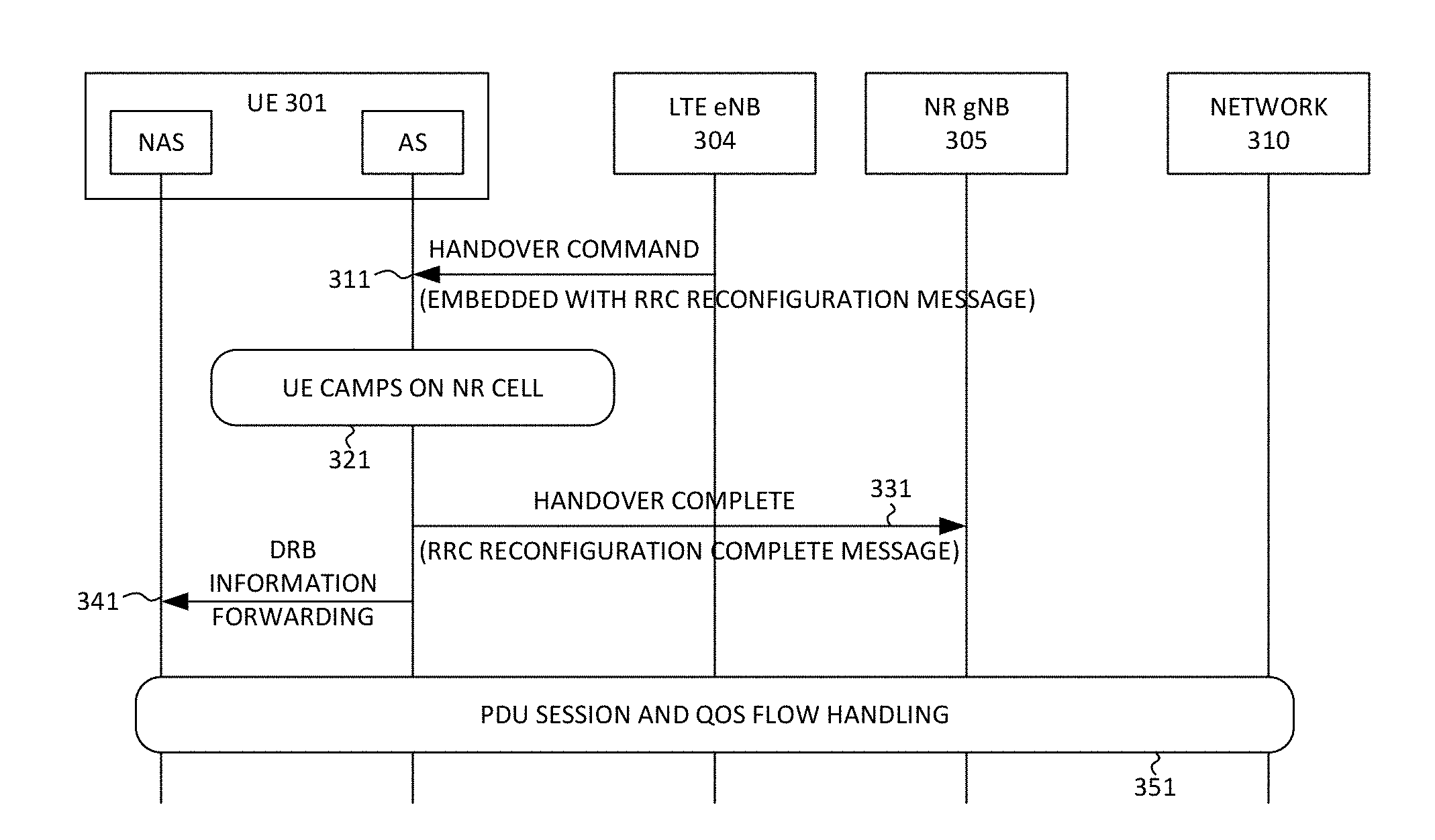
[0026] FIG. 3 illustrates a first embodiment of PDU session and QoS flow handling after a handover procedure in accordance with one novel aspects. In the example of FIG. 3, UE 301 is originally served by an LTE eNB 304. In step 311, eNB 304 sends a handover command to the AS layer of UE 301, triggering an inter-system handover procedure. The target base station is NR gNB 305. The handover command is embedded with an RRC reconfiguration message, which provides configuration information for UE to handover to the target NR cell. From AS layer point of view, the RRC reconfiguration information element (IE) comprises radio bearer configuration, which adds DRBs and associated PDU sessions/QoS flows. For example, a "radioBearerConfig" comprises "drb-ToAddModList", which comprises "sdap-Config", which further comprises pdu-Sessoin: indicates PDU session ID; defaultDRB: indicates whether default DRB is true; mappedQoS-FlowsToAdd: indicates a sequence of to be mapped QoS flows; and mappedQoS-FlowsToRelease: indicates a sequence of to be released QoS flows. Therefore, based on the RRC reconfiguration IE, UE 301 is able to determine which PDU session(s) to be reactivated, and which QoS flow(s) do not have mapping DRB.
[0027] In step 321, UE 301 camps on the target NR cell. In step 331, UE 301 sends a handover complete to the target base station NR gNB 305. The handover complete comprises an RRC reconfiguration complete message. In step 341, the AS layer of UE 301 sends DRB information forwarding to the NAS layer of UE 301. This is an internal signaling and the information is mainly based on the content of the RRC reconfiguration message. In step 351, UE 301 performs PDU session and QoS flow handling after the handover is completed. In accordance with one novel aspect, UE 301 determines which PDU session is to be reactivated upon the handover, and whether each QoS flow of the reactivated PDU session is supported by a mapping DRB. If there is unsupported QoS flow(s), then UE 301 will further determine whether the QoS flow is associated with a default QoS rule or not, and perform corresponding action.
[0028] FIG. 4 illustrates a flow chart of a novel PDU session and QoS flow handling when a QoS flow has no mapping DRB after a PDU session is reactivated. A UE may have established one or more PDU sessions with the network, and each PDU session is configured with one or more QoS flows and one or more QoS rules. One of the QoS flow is associated with a default QoS rule, which is required for each PDU session. For the PDU session and QoS handling, the UE starts with one PDU session (step 411). In step 412, the UE determines whether the PDU session is reactivated, e.g., due to an RRC reconfiguration. If yes, then the UE goes to step 413 and determines whether a selected QoS flow is supported by a mapping DRB. If yes, then the UE goes to step 414 and checks whether the PDU session has more QoS flows. If there are more QoS flows, then the UE goes back to step 413 and select another QoS flow to check. If the answer to step 413 is no, then the UE goes to step 415 and checks whether the QoS flow is associated with a default QoS rule.
[0029] If the QoS flow is associated with the default QoS rule, then the entire PDU session is impacted. As a result, the UE needs to handle the PDU session accordingly. In a first option (step 421), the UE release the PDU session implicitly or explicitly. If implicitly, the UE releases the PDU session locally, and optionally initiate a registration procedure for synchronization with the network. If explicitly, the UE initiates a PDU session release procedure to release the PDU session. In a second option (422), the UE sends 5GSM status message with proper cause to inform the network. In a third option (423), the UE assumes the PDU session is not reactivated, and optionally initiates a registration procedure with the network for synchronization.
[0030] If the QoS flow is not associated with the default QoS rule, then only the QoS flow is impacted. As a result, the UE needs to handle the QoS flow accordingly. In a first option (431), the UE deletes the QoS flow implicitly or explicitly. If implicitly, the UE deletes the QoS flow locally, and optionally sends a PDU session modification to the network. If explicitly, the UE deletes the QoS flow by using a PDU session modification procedure. In a second option (432), the UE sends 5GSM status message with proper cause to inform the network. In a third option (433), the UE assumes the QoS flow is not reactivated, and optionally initiates a registration procedure with the network for synchronization.
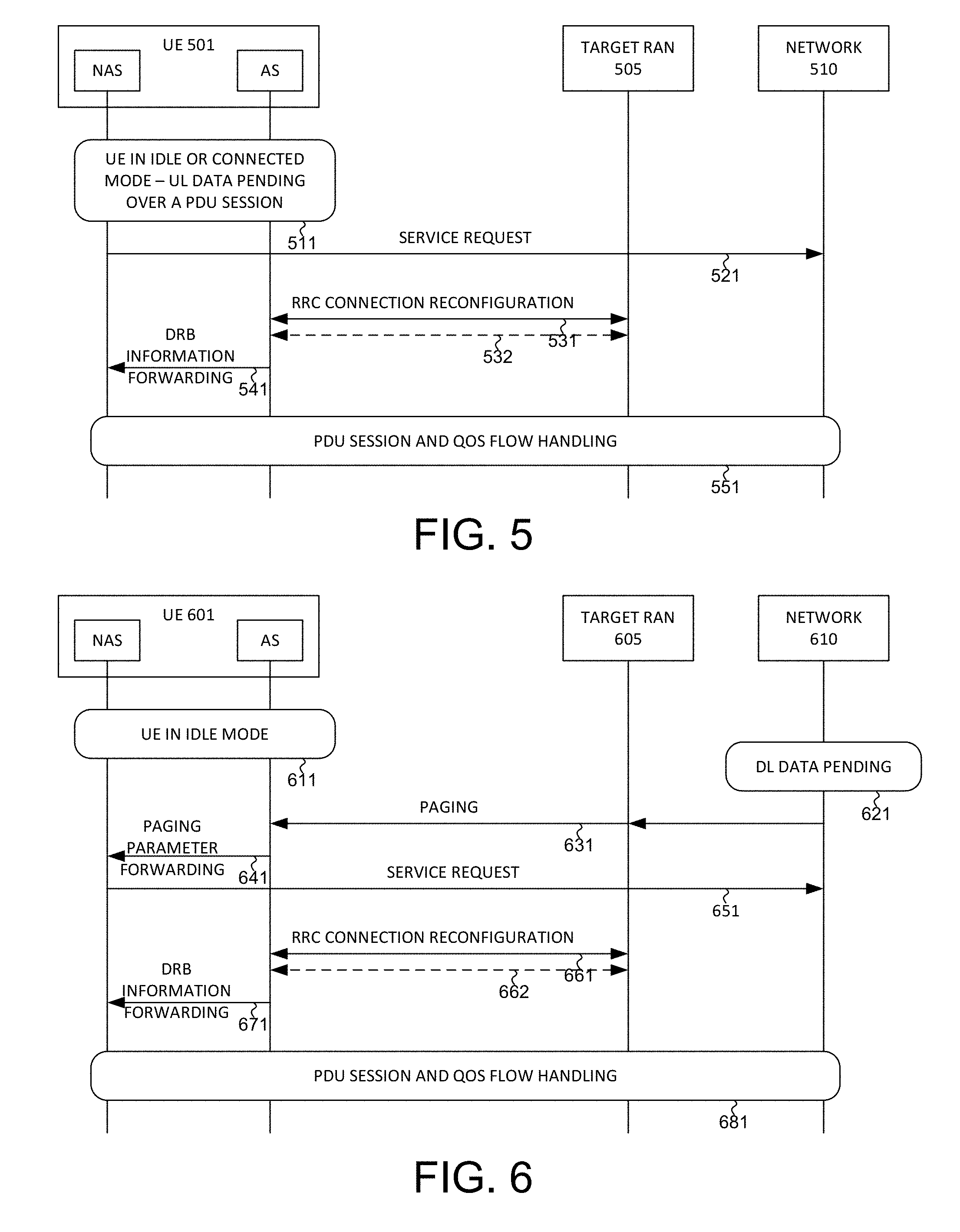
[0031] FIG. 5 illustrates a second embodiment of PDU session and QoS flow handling after a UE-initiated service request procedure in accordance with one novel aspects. In the example of FIG. 5, UE 501 is originally in RRC idle mode or in RRC connected mode. In step 311, UE 501 has uplink data pending over a PDU session, which is inactive. If UE is in idle mode, then UE needs to go to connected mode and reactivate the PDU session via a service request; if UE is in connected mode, then UE also needs to reactivate the PDU session via a service request. In step 521, UE 501 sends a service request from NAS layer to the network to reactivate the PDU session.
[0032] In step 531, the target RAN 505 sends an RRC reconfiguration message to the AS layer of UE 501 in response to the service request. From AS layer point of view, the RRC reconfiguration message comprises radio bearer configuration, which adds DRBs and associated PDU sessions/QoS flows. Note that the RAN may send multiple RRC reconfiguration messages subsequently, e.g., another RRC reconfiguration message in step 532. Each RRC reconfiguration message may provide additional radio bearer configuration for UE 501. As a result, UE 501 may need to wait for some time in order to receive all the RRC reconfiguration messages. In step 541, the AS layer of UE 501 sends DRB information forwarding to the NAS layer of UE 501. This is an internal signaling and the information is mainly based on the content of the RRC reconfiguration message(s). In step 551, UE 501 performs PDU session and QoS flow handling after the handover is completed. In accordance with one novel aspect, UE 501 determines which PDU session is to be reactivated upon the handover, and whether each QoS flow of the reactivated PDU session is supported by a mapping DRB. If there is unsupported QoS flow(s), then UE 501 will further determine whether the QoS flow is associated with a default QoS rule or not, and perform corresponding actions.
[0033] FIG. 6 illustrates a third embodiment of PDU session and QoS flow handling after a network-initiated service request procedure in accordance with one novel aspects. In the example of FIG. 6, UE 601 is in RRC idle mode (step 611). In step 621, network 610 has downlink data pending for UE 601. In step 631, network 610 sends a paging message to the AS layer of UE 601 via RAN 605. In step 641, the AS layer sends paging parameter forwarding to the NAS layer of UE 601. Upon receiving the paging, UE 601 knows that it needs to go to RRC connected mode via a service request. In step 651, UE 601 sends a service request from NAS layer to the network to reactivate the PDU session. In step 661, the target RAN 505 sends an RRC reconfiguration message to the AS layer of UE 501 in response to the service request. From AS layer point of view, the RRC reconfiguration message comprises radio bearer configuration, which adds DRBs and associated PDU sessions/QoS flows. Note that the RAN may send multiple RRC reconfiguration messages subsequently, e.g., another RRC reconfiguration message in step 662. Each RRC reconfiguration message may provide additional radio bearer configuration for UE 601. In step 671, the AS layer of UE 601 sends DRB information forwarding to the NAS layer of UE 601. This is an internal signaling and the information is mainly based on the content of the RRC reconfiguration message(s). In step 681, UE 601 performs PDU session and QoS flow handling after the handover is completed. In accordance with one novel aspect, UE 601 determines which PDU session is to be reactivated upon the handover, and whether each QoS flow of the reactivated PDU session is supported by a mapping DRB. If there is unsupported QoS flow(s), then UE 601 will further determine whether the QoS flow is associated with a default QoS rule or not, and perform corresponding action.
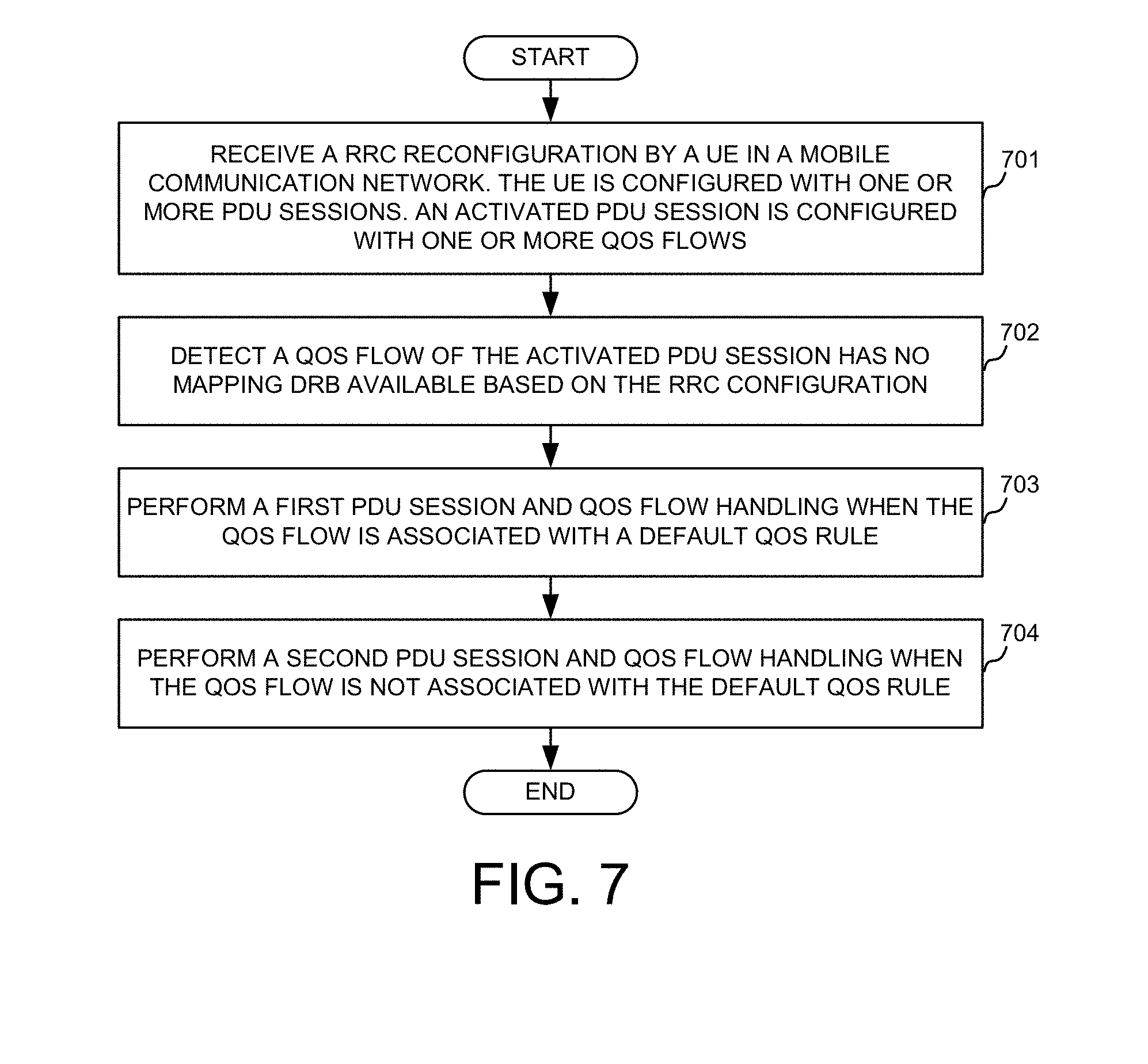
[0034] FIG. 7 is a flow chart of a method of PDU session and QoS flow handling in accordance with one novel aspect of the present invention. In step 701, a UE receives a radio resource control (RRC) reconfiguration in a mobile communication network. The UE is configured with one or more Protocol data unit (PDU) sessions, and an activated PDU session is configured with one or more QoS flows. In step 702, the UE detects that a QoS flow of the activated PDU session has no mapping data radio bearer (DRB) available based on the RRC reconfiguration. In step 703, the UE performs a first PDU session and QoS flow handling when the QoS flow is associated with a default QoS rule. In step 704, the UE performs a second PDU session and QoS flow handing when the QoS flow is not associated with the default QoS rule.
[0035] Although the present invention has been described in connection with certain specific embodiments for instructional purposes, the present invention is not limited thereto. Accordingly, various modifications, adaptations, and combinations of various features of the described embodiments can be practiced without departing from the scope of the invention as set forth in the claims.
* * * * *
D00000
D00001
D00002
D00003
D00004
XML
uspto.report is an independent third-party trademark research tool that is not affiliated, endorsed, or sponsored by the United States Patent and Trademark Office (USPTO) or any other governmental organization. The information provided by uspto.report is based on publicly available data at the time of writing and is intended for informational purposes only.
While we strive to provide accurate and up-to-date information, we do not guarantee the accuracy, completeness, reliability, or suitability of the information displayed on this site. The use of this site is at your own risk. Any reliance you place on such information is therefore strictly at your own risk.
All official trademark data, including owner information, should be verified by visiting the official USPTO website at www.uspto.gov. This site is not intended to replace professional legal advice and should not be used as a substitute for consulting with a legal professional who is knowledgeable about trademark law.