Systems And Methods For Data Management Of Multiple Cloud Services
Kasturi; Rohini ; et al.
U.S. patent application number 16/375243 was filed with the patent office on 2019-10-10 for systems and methods for data management of multiple cloud services. The applicant listed for this patent is Veritas Technologies LLC. Invention is credited to Stuart Carter, Shailesh Dargude, Satish Grandhi, Rohini Kasturi, Srinivas Kavuri, Vibhu Pratap, Vijay Rajaram, Yogendra Singh.
| Application Number | 20190310791 16/375243 |
| Document ID | / |
| Family ID | 66429545 |
| Filed Date | 2019-10-10 |


| United States Patent Application | 20190310791 |
| Kind Code | A1 |
| Kasturi; Rohini ; et al. | October 10, 2019 |
SYSTEMS AND METHODS FOR DATA MANAGEMENT OF MULTIPLE CLOUD SERVICES
Abstract
The disclosed computer-implemented method for data management of multiple cloud services may include receiving, via a visibility application, a command for managing data hosted on a plurality of content sources. The commands from the visibility application may be modified and indirectly routed to the plurality of content sources. The method may include accessing, in response to the command, the plurality of content sources, and collecting and aggregating, from the plurality of content sources, metadata associated with the data. The method may also include analyzing the aggregated metadata. The method may further include providing, for presentation by the visibility application, results of the metadata analysis. Various other methods, systems, and computer-readable media are also disclosed.
| Inventors: | Kasturi; Rohini; (Santa Clara, CA) ; Grandhi; Satish; (Santa Clara, CA) ; Dargude; Shailesh; (Santa Clara, CA) ; Pratap; Vibhu; (Santa Clara, CA) ; Rajaram; Vijay; (Santa Clara, CA) ; Kavuri; Srinivas; (Santa Clara, CA) ; Carter; Stuart; (Santa Clara, CA) ; Singh; Yogendra; (Santa Clara, CA) | ||||||||||
| Applicant: |
|
||||||||||
|---|---|---|---|---|---|---|---|---|---|---|---|
| Family ID: | 66429545 | ||||||||||
| Appl. No.: | 16/375243 | ||||||||||
| Filed: | April 4, 2019 |
Related U.S. Patent Documents
| Application Number | Filing Date | Patent Number | ||
|---|---|---|---|---|
| 62653541 | Apr 5, 2018 | |||
| Current U.S. Class: | 1/1 |
| Current CPC Class: | G06F 3/0647 20130101; G06F 16/907 20190101; G06F 3/0604 20130101; G06F 3/0652 20130101; G06F 3/0659 20130101; G06F 3/067 20130101; G06F 9/5072 20130101 |
| International Class: | G06F 3/06 20060101 G06F003/06; G06F 16/907 20060101 G06F016/907 |
Claims
1. A computer-implemented method for data management of multiple cloud services, at least a portion of the method being performed by a computing device comprising at least one processor, the method comprising: receiving, via a visibility application, a command for managing data hosted on a plurality of content sources, wherein commands from the visibility application are modified and indirectly routed to the plurality of content sources; accessing, in response to the command, the plurality of content sources; collecting and aggregating, from the plurality of content sources, metadata associated with the data; analyzing the aggregated metadata; and providing, for presentation by the visibility application, results of the metadata analysis.
2. The method of claim 1, wherein collecting the metadata further comprises collecting user metadata of users associated with the data.
3. The method of claim 1, wherein collecting the metadata further comprises access metadata corresponding to operation events associated with the data.
4. The method of claim 1, further comprising verifying a user for issuing commands, wherein the command is issued by the verified user.
5. The method of claim 1, further comprising: receiving, in response to the presentation of the results by the visibility application, a second command for managing the data; and accessing the plurality of content services to perform the second command.
6. The method of claim 5, wherein the second command comprises a command to move portions of the data through a storage hierarchy based on the metadata analysis, wherein the storage hierarchy prioritizes storage devices of the plurality of content sources based on type of storage device.
7. The method of claim 5, wherein the second command comprises a command to delete portions of the data based on the metadata analysis.
8. The method of claim 1, wherein the plurality of content sources comprises a cloud service.
9. The method of claim 1, wherein the plurality of content sources comprises a private data server.
10. A system for data management of multiple cloud services, the system comprising: at least one physical processor; physical memory comprising computer-executable instructions that, when executed by the physical processor, cause the physical processor to: receive, via a visibility application, a command for managing data hosted on a plurality of content sources, wherein commands from the visibility application are modified and indirectly routed to the plurality of content sources; access, in response to the command, the plurality of content sources; collect and aggregate, from the plurality of content sources, metadata associated with the data; analyze the aggregated metadata; and provide, for presentation by the visibility application, results of the metadata analysis.
11. The system of claim 10, wherein collecting the metadata further comprises collecting user metadata of users associated with the data.
12. The system of claim 10, wherein collecting the metadata further comprises access metadata corresponding to operation events associated with the data.
13. The system of claim 10, wherein the instructions further comprise instructions for verifying a user for issuing commands, wherein the command is issued by the verified user.
14. The system of claim 10, wherein the instructions further comprise instructions for: receiving, in response to the presentation of the results by the visibility application, a second command for managing the data; and accessing the plurality of content services to perform the second command.
15. The system of claim 14, wherein the second command comprises a command to move portions of the data through a storage hierarchy based on the metadata analysis, wherein the storage hierarchy prioritizes storage devices of the plurality of content sources based on type of storage device.
16. The system of claim 14, wherein the second command comprises a command to delete portions of the data based on the metadata analysis.
17. The system of claim 10, wherein the plurality of content sources comprises at least one of a cloud service and a private data server.
18. A non-transitory computer-readable medium comprising one or more computer-executable instructions that, when executed by at least one processor of a computing device, cause the computing device to: receive, via a visibility application, a command for managing data hosted on a plurality of content sources, wherein commands from the visibility application are modified and indirectly routed to the plurality of content sources; access, in response to the command, the plurality of content sources; collect and aggregate, from the plurality of content sources, metadata associated with the data; analyze the aggregated metadata; and provide, for presentation by the visibility application, results of the metadata analysis.
19. The non-transitory computer-readable medium of claim 18, wherein the instructions further comprise instructions for: receiving, in response to the presentation of the results by the visibility application, a second command for managing the data; and accessing the plurality of content services to perform the second command.
20. The non-transitory computer-readable medium of claim 19, wherein the second command comprises at least one of: a command to move portions of the data through a storage hierarchy based on the metadata analysis, wherein the storage hierarchy prioritizes storage devices of the plurality of content sources based on type of storage device; and a command to delete portions of the data based on the metadata analysis.
Description
CROSS REFERENCE TO RELATED APPLICATION
[0001] This application claims the benefit of U.S. Provisional Application No. 62/653,541, filed Apr. 5, 2018, the disclosure of which is incorporated, in its entirety, by this reference.
BACKGROUND
[0002] Companies and end users increasingly store and use data across an ever-growing number of platforms and locations, including internally managed on-premise storage solutions, externally managed cloud-based services, or a mixture of one or more of the same. Unfortunately, data sources often utilize wildly different taxonomies or techniques for storing, classifying, protecting, or otherwise managing data. These differing approaches to managing data can make it especially difficult for a company or an end user to consistently and accurately manage data stored across disparate data sources. For example, a company that utilizes a mixture of on-premise and cloud-based data sources for its data may have difficulty centrally managing data in a way that satisfies various government regulations (such as the European Union's General Data Protection Regulation) due to the differing ways in which these data sources store, classify, protect, or otherwise manage such data.
[0003] The present disclosure, therefore, identifies and addresses a need for systems and methods for data management of multiple cloud services.
SUMMARY
[0004] As will be described in greater detail below, the present disclosure describes various systems and methods for data management of multiple cloud services.
[0005] In one example, a method for data management of multiple cloud services may include (i) receiving, via a visibility application, a command for managing data hosted on a plurality of content sources, wherein commands from the visibility application are modified and indirectly routed to the plurality of content sources, (ii) accessing, in response to the command, the plurality of content sources, (iii) collecting and aggregating, from the plurality of content sources, metadata associated with the data, (iv) analyzing the aggregated metadata, and (v) providing, for presentation by the visibility application, results of the metadata analysis.
[0006] In some examples, collecting the metadata may further comprise collecting user metadata of users associated with the data. In some examples, collecting the metadata may further comprise access metadata corresponding to operation events associated with the data. In some examples, the method may further comprise verifying a user for issuing commands. The command may be issued by the verified user.
[0007] In some examples, the method may further comprise (a) receiving, in response to the presentation of the results by the visibility application, a second command for managing the data, and (b) accessing the plurality of content services to perform the second command. The second command may comprise a command to move portions of the data through a storage hierarchy based on the metadata analysis. The storage hierarchy may prioritize storage devices of the plurality of content sources based on type of storage device. The second command may comprise a command to delete portions of the data based on the metadata analysis.
[0008] In some examples, the plurality of content sources may comprise a cloud service. In some examples, the plurality of content sources may comprise a private data server.
[0009] In one embodiment, a system for data management of multiple cloud services may include at least one physical processor and physical memory that includes computer-executable instructions that, when executed by the physical processor, cause the physical processor to (i) receive, via a visibility application, a command for managing data hosted on a plurality of content sources, wherein commands from the visibility application are modified and indirectly routed to the plurality of content sources, (ii) access, in response to the command, the plurality of content sources, (iii) collect and aggregate, from the plurality of content sources, metadata associated with the data, (iv) analyze the aggregated metadata, and (v) provide, for presentation by the visibility application, results of the metadata analysis.
[0010] In some examples, collecting the metadata may further comprise collecting user metadata of users associated with the data. In some examples, collecting the metadata may further comprise access metadata corresponding to operation events associated with the data. In some examples, the instructions may further comprise instructions for verifying a user for issuing commands. The command may be issued by the verified user.
[0011] In some examples, the instructions may further comprise instructions for (a) receiving, in response to the presentation of the results by the visibility application, a second command for managing the data, and (b) accessing the plurality of content services to perform the second command. The second command may comprise a command to move portions of the data through a storage hierarchy based on the metadata analysis. The storage hierarchy may prioritize storage devices of the plurality of content sources based on type of storage device. The second command may comprise a command to delete portions of the data based on the metadata analysis. In some examples, the plurality of content sources may comprise at least one of a cloud service and a private data server.
[0012] In some examples, the above-described method may be encoded as computer-readable instructions on a non-transitory computer-readable medium. For example, a computer-readable medium may include one or more computer-executable instructions that, when executed by at least one processor of a computing device, may cause the computing device to (i) receive, via a visibility application, a command for managing data hosted on a plurality of content sources, wherein commands from the visibility application are modified and indirectly routed to the plurality of content sources, (ii) access, in response to the command, the plurality of content sources, (iii) collect and aggregate, from the plurality of content sources, metadata associated with the data, (iv) analyze the aggregated metadata, and (v) provide, for presentation by the visibility application, results of the metadata analysis.
[0013] In some examples, the instructions may further comprise instructions for (a) receiving, in response to the presentation of the results by the visibility application, a second command for managing the data, and (b) accessing the plurality of content services to perform the second command. In some examples, the second command may comprise at least one of a command to move portions of the data through a storage hierarchy based on the metadata analysis, wherein the storage hierarchy prioritizes storage devices of the plurality of content sources based on type of storage device, and a command to delete portions of the data based on the metadata analysis.
[0014] Features from any of the embodiments described herein may be used in combination with one another in accordance with the general principles described herein. These and other embodiments, features, and advantages will be more fully understood upon reading the following detailed description in conjunction with the accompanying drawings and claims.
BRIEF DESCRIPTION OF THE DRAWINGS
[0015] The accompanying drawings illustrate a number of example embodiments and are a part of the specification. Together with the following description, these drawings demonstrate and explain various principles of the present disclosure.
[0016] FIG. 1 is a block diagram of an example system for data management of multiple cloud services.
[0017] FIG. 2 is a block diagram of an additional example system for data management of multiple cloud services.
[0018] FIG. 3 is a flow diagram of an example method for data management of multiple cloud services.
[0019] FIG. 4 is a block diagram of an example platform architecture for data management of multiple cloud services.
[0020] FIG. 5 is an example workflow of a platform architecture for data management of multiple cloud services.
[0021] FIG. 6 is a block diagram of an example computing system capable of implementing one or more of the embodiments described and/or illustrated herein.
[0022] FIG. 7 is a block diagram of an example computing network capable of implementing one or more of the embodiments described and/or illustrated herein.
[0023] Throughout the drawings, identical reference characters and descriptions indicate similar, but not necessarily identical, elements. While the example embodiments described herein are susceptible to various modifications and alternative forms, specific embodiments have been shown by way of example in the drawings and will be described in detail herein. However, the example embodiments described herein are not intended to be limited to the particular forms disclosed. Rather, the present disclosure covers all modifications, equivalents, and alternatives falling within the scope of the appended claims.
DETAILED DESCRIPTION OF EXAMPLE EMBODIMENTS
[0024] The present disclosure is generally directed to systems and methods for data management of multiple cloud services. As organizations require increasing data storage demands, they may rely on various data storage solutions, including externally managed cloud-based services and/or internally managed on-premise storage solutions. Without a pre-defined data model and/or due to various incompatibilities between the storage solutions, an amount of unstructured data may grow to be prohibitively unmanageable. As will be explained in greater detail below, a platform for multi-cloud data management may access multiple content sources storing data, and aggregating and analyzing metadata associated with the data. The platform may provide an application programming interface (API) for a visibility application which may present analysis results and present a user interface for a user to issue commands to the platform. The platform may provide, via the visibility application, tools to better manage unstructured data. For example, stale data may be deleted or archived to cheaper storage solutions. The systems and methods described herein may improve use of computing and other resources needed for data storage. This may allow businesses to better control data and to better manage costs and overhead associated with data storage.
[0025] In addition, the systems and methods described herein may improve the functioning of a computing device by analyzing data to more efficiently store the data, and providing interfaces to enable efficient data management. These systems and methods may also improve the field of data management by providing a platform enabling efficient data storage.
[0026] The following will provide, with reference to FIGS. 1-2, detailed descriptions of example systems for data management of multiple cloud services. Detailed descriptions of corresponding computer-implemented methods will also be provided in connection with FIG. 3. Detailed descriptions of an example platform architecture for data management of multiple cloud services will be provided in connection with FIG. 4. Detailed descriptions of an example workflow for data management of multiple cloud services will be provided in connection with FIG. 5. In addition, detailed descriptions of an example computing system and network architecture capable of implementing one or more of the embodiments described herein will be provided in connection with FIGS. 6 and 7, respectively.
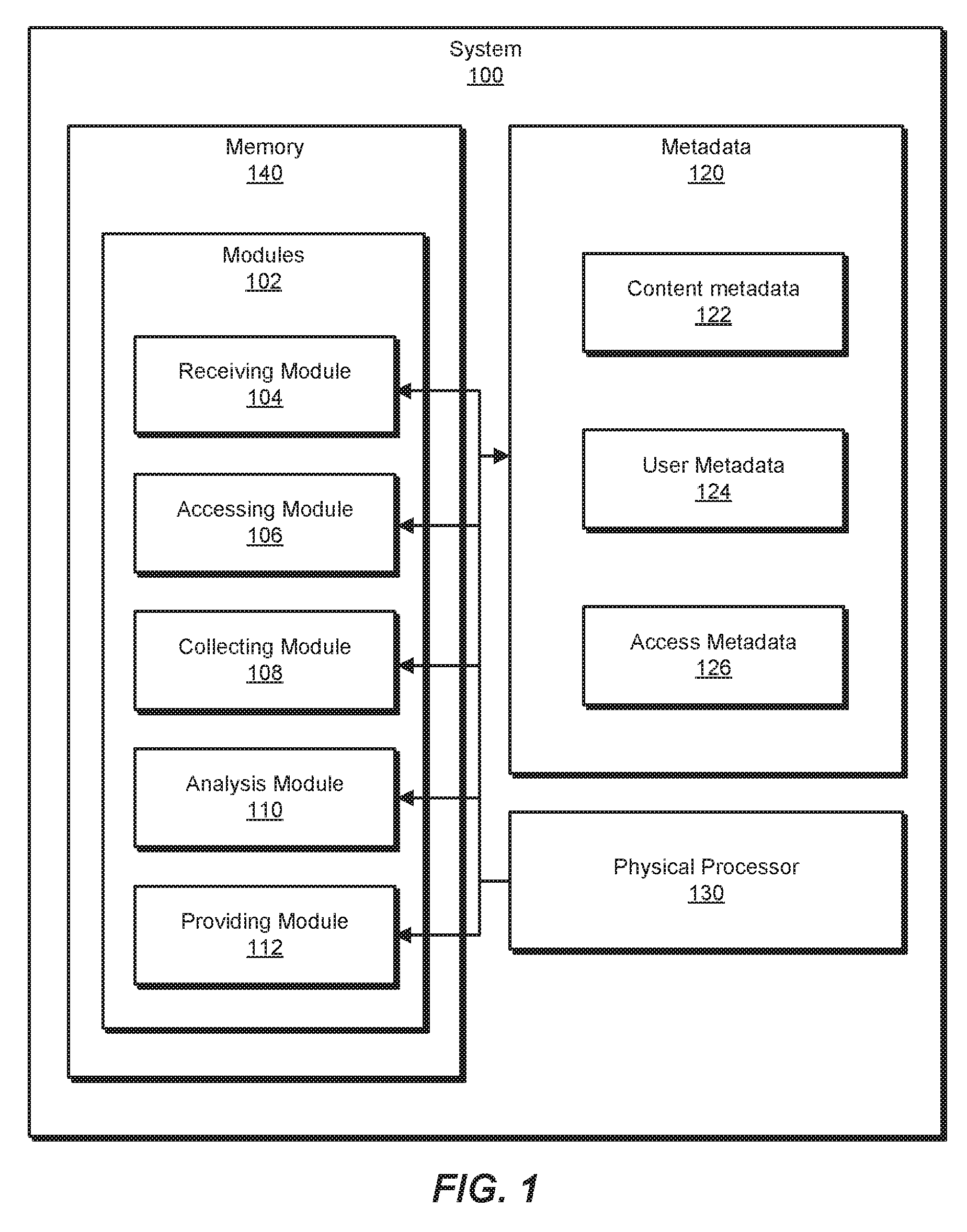
[0027] FIG. 1 is a block diagram of an example system 100 for data management of multiple cloud services. As illustrated in this figure, example system 100 may include one or more modules 102 for performing one or more tasks. As will be explained in greater detail below, modules 102 may include a receiving module 104, a accessing module 106, a collecting module 108, an analysis module 110, and a providing module 112. Although illustrated as separate elements, one or more of modules 102 in FIG. 1 may represent portions of a single module or application.
[0028] In certain embodiments, one or more of modules 102 in FIG. 1 may represent one or more software applications or programs that, when executed by a computing device, may cause the computing device to perform one or more tasks. For example, and as will be described in greater detail below, one or more of modules 102 may represent modules stored and configured to run on one or more computing devices, such as the devices illustrated in FIG. 2 (e.g., computing device 202 and/or servers 206A-B). One or more of modules 102 in FIG. 1 may also represent all or portions of one or more special-purpose computers configured to perform one or more tasks.
[0029] As illustrated in FIG. 1, example system 100 may also include one or more memory devices, such as memory 140. Memory 140 generally represents any type or form of volatile or non-volatile storage device or medium capable of storing data and/or computer-readable instructions. In one example, memory 140 may store, load, and/or maintain one or more of modules 102. Examples of memory 140 include, without limitation, Random Access Memory (RAM), Read Only Memory (ROM), flash memory, Hard Disk Drives (HDDs), Solid-State Drives (SSDs), optical disk drives, caches, variations or combinations of one or more of the same, and/or any other suitable storage memory.
[0030] As illustrated in FIG. 1, example system 100 may also include one or more physical processors, such as physical processor 130. Physical processor 130 generally represents any type or form of hardware-implemented processing unit capable of interpreting and/or executing computer-readable instructions. In one example, physical processor 130 may access and/or modify one or more of modules 102 stored in memory 140. Additionally or alternatively, physical processor 130 may execute one or more of modules 102 to facilitate data management of multiple cloud services. Examples of physical processor 130 include, without limitation, microprocessors, microcontrollers, Central Processing Units (CPUs), Field-Programmable Gate Arrays (FPGAs) that implement softcore processors, Application-Specific Integrated Circuits (ASICs), portions of one or more of the same, variations or combinations of one or more of the same, and/or any other suitable physical processor.
[0031] As illustrated in FIG. 1, example system 100 may also include one or more additional elements, such as metadata 120. Metadata 120 generally represents any type or form of metadata associated with data (e.g., data 228 in FIG. 2) hosted on content sources (e.g., servers 206A-B in FIG. 2). The data may be, for instance, files, documents, photos, videos, content, etc. Metadata 120 may represent information about the data, such as various attributes and properties, in one example, metadata 120 may include specific types of metadata, such as content metadata 122, user metadata 124, and access metadata 126. Content metadata 122 may represent metadata closely associated with the data, such as file types, file sizes, file locations, etc. User metadata 124 may represent metadata associated with users who may access the data, such as user identification, user profile information (e.g., department, manager, email address, etc.), permissions, group memberships, etc. Access metadata 126 may represent metadata of operation events associated with the data, including details of file operations on the data. Examples of access metadata 126 may include, without limitation, timestamps, users performing operations, types of operations (e.g., file creation, modification, moving, etc.), and other related details.
[0032] Example system 100 in FIG. 1 may be implemented in a variety of ways. For example, all or a portion of example system 100 may represent portions of example system 200 in FIG. 2. As shown in FIG. 2, system 200 may include a computing device 202 in communication with servers 206A-B via a network 204. In one example, all or a portion of the functionality of modules 102 may be performed by computing device 202, servers 206A-B, and/or any other suitable computing system. As will be described in greater detail below, one or more of modules 102 from FIG. 1 may, when executed by at least one processor of computing device 202 and/or server 206, enable computing device 202 and/or servers 206A-B to manage data from multiple cloud services. For example, and as will be described in greater detail below, one or more of modules 102 may cause computing device 202 and/or servers 206A-B to recite steps of method claim using FIG. 2
[0033] Computing device 202 generally represents any type or form of computing device capable of reading computer-executable instructions. Computing device 202 may be a platform server which may be a backend server hosting a platform for multi-cloud data management as will be described below. Additional examples of computing device 202 include, without limitation, laptops, tablets, desktops, servers, cellular phones, Personal Digital Assistants (PDAs), multimedia players, embedded systems, wearable devices (e.g., smart watches, smart glasses, etc.), smart vehicles, smart packaging (e.g., active or intelligent packaging), gaming consoles, so-called Internet-of-Things devices (e.g., smart appliances, etc.), variations or combinations of one or more of the same, and/or any other suitable computing device.
[0034] Servers 206A-B generally represent any type or form of computing device that is capable of hosting content such as data 228. Servers 206A-B may be cloud servers or servers hosting cloud services and/or other private data hosting services. Additional examples of server 206 include, without limitation, backend servers, application servers, web servers, storage servers, and/or database servers configured to run certain software applications and/or provide various web, storage, and/or database services. Although illustrated as two entities in FIG. 2, servers 206A-B may include and/or represent a plurality of servers that work and/or operate in conjunction with one another.
[0035] Data 228 generally represents any type or form of data. Examples of data 228 may include, without limitation, files, documents, photos, videos, digital representations of information, etc. Data 228 may be stored across and accessed from multiple servers, such as servers 206A-B. Data 228 may be unstructured data. The term "unstructured data," as used herein, generally refers to data which may not be organized in a pre-defined manner or otherwise does not have a pre-defined data model. Unstructured data, particularly unstructured data hosted on various noncollaborative cloud services, may be difficult to manage as it scales in size and/or amount.
[0036] Network 204 generally represents any medium or architecture capable of facilitating communication or data transfer. In one example, network 204 may facilitate communication between computing device 202 and server 206. In this example, network 204 may facilitate communication or data transfer using wireless and/or wired connections. Examples of network 204 include, without limitation, an intranet, a Wide Area Network (WAN), a Local Area Network (LAN), a Personal Area Network (PAN), the Internet, Power Line Communications (PLC), a cellular network (e.g., a Global System for Mobile Communications (GSM) network), portions of one or more of the same, variations or combinations of one or more of the same, and/or any other suitable network.
[0037] FIG. 3 is a flow diagram of an example computer-implemented method 300 for data management of multiple cloud services. The steps shown in FIG. 3 may be performed by any suitable computer-executable code and/or computing system, including system 100 in FIG. 1, system 200 in FIG. 2, and/or variations or combinations of one or more of the same. In one example, each of the steps shown in FIG. 3 may represent an algorithm whose structure includes and/or is represented by multiple sub-steps, examples of which will be provided in greater detail below.
[0038] As illustrated in FIG. 3, at step 302 one or more of the systems described herein may receive, via a visibility application, a command for managing data hosted on a plurality of content sources, wherein commands from the visibility application are modified and indirectly routed to the plurality of content sources. For example, receiving module 104 may, as part of computing device 202 in FIG. 2, receive a command for managing data 228.
[0039] The term "visibility application," as used herein, generally refers to an application which may be used for monitoring application performance. Examples of visibility applications include, without limitation, diagnostic applications, security applications, administrative tools, etc. In some examples, visibility applications may refer more generally to an application which may be client-facing in order to provide a user interface and accesses an underlying platform and/or backend service such that the user may not directly access the platform.
[0040] FIG. 4 illustrates a platform environment 400 including a visibility application 462, a presentation layer 460, a control plane 470, an analytics plane 480, a data plane 490, and content sources 406A-B. Visibility application 462 may be a visibility application which interfaces with presentation layer 460, although in some implementations presentation layer 460 may include or otherwise integrate visibility application 462. A platform 450 may be a multi-cloud data management platform that may include various microservices whose architecture may be represented by presentation layer 460, control plane 470, analytics plane 480, and data plane 490. The multi-cloud data management platform may be implemented with, for example, computing device 202. Content sources 406A-B may correspond to various cloud service and may be implanted with servers 206A-B.
[0041] Presentation layer 460 may provide an API for visibility application 462 to interface with platform 450. Presentation layer 460 may allow various applications capable of interfacing with platform 450 to be developed. These applications may leverage the data management functionalities provided by platform 450 without needing to directly access cloud services such as content sources 406A-B. Visibility application 462 may provide a user interface to the user to allow the user to issue commands and see results.
[0042] Control plane 470 may provide a control logic for coordinating actions amongst the various layers of platform 450. For instance, control plane 470 may receive commands from the user via visibility application 462 and presentation layer 460. Control plane 470 may accordingly modify the received commands and issue appropriate commands to analytics plane 480 and/or data plane 490 as needed to perform the received commands. Control plane 470 may further send or facilitate sending results of the performed commands to presentation layer 460.
[0043] Analytics plane 480 may provide analysis logic for performing analysis on data stored in content sources 406A-B. Analytics plane 480 may utilize one or more machine learning systems and/or other analytics tools to perform analysis.
[0044] Data plane 490 may provide an interface for accessing content sources 406A-B. Data plane 490 may be configured to access various types of data storage solutions, such as cloud services, private data servers, database servers, etc. Data plane 490 may facilitate communication between platform 450 and content sources 406A-B.
[0045] In some implementations, platform 450 may be deployed on a single server or computing device. In other implementations, platform 450 may be deployed across multiple servers. For example, data plane 490 may be deployed close to data 228, such as on the cloud service and/or private data server (e.g., server 206A and/or server 206B). Analytics plane 480 may also be deployed close to data 228. In some implementations, multiple iterations of analytics plane 480 and/or data plane 490 may be deployed, such as on each cloud service and/or private data server. Control plane 470 may be deployed in a centralized location which may be close to the user, such as on a client computing device or company server.
[0046] Returning to FIG. 3, the systems described herein may perform step 302 in a variety of ways. In one example, the command may be a general command, such as a command to begin analysis of data (e.g., data 228) and/or to continue ongoing analysis. In one example, the command may be a broad command, such as a command to reorganize the data. In one example, the command may be a specific command, such as a command to move and/or delete a particular file. In other examples, the command may not be a direct command from the user but rather a command in response to the user initiating visibility application 462 and/or platform 450 in general.
[0047] In addition, the user may first be verified such that the command is issued by the verified user. Turning to FIG. 5, FIG. 5 illustrates a workflow 500 of using a multi-cloud data management platform such as platform 450. At 502, a user may log into a visibility application such as visibility application 462. At 504, the user may issue a command to the platform.
[0048] Returning to FIG. 3, at step 304 one or more of the systems described herein may access, in response to the command, the plurality of content sources. For example, accessing module 106 may, as part of computing device 202 in FIG. 2, access servers 206A-B.
[0049] The systems described herein may perform step 304 in a variety of ways. In one example, data plane 490 may access content sources 406A-B. Data plane 490 may be controlled by control plane 470 to access content sources 406A-B in response to the command received from visibility application 462 via presentation layer 460.
[0050] As illustrated in FIG. 5, at 506 the control plane may issue a command to the data plane in response to the received command. The received command may be a command to initiate data analysis which may comprise one or more subcommands coordinated by control plane 470. For example, the data analysis may require collecting and aggregating metadata of the data, analyzing the metadata, and providing the analysis results for presentation. In other examples the received command may be a specific command to create, modify, move, and/or delete data, which control plane 470 may accordingly modify to send appropriate commands to data plane 490. For instance, control plane 470 may specify to data plane 490 which of content source 406A and/or content source 406B to access and what operations to perform.
[0051] Turning back to FIG. 3, at step 306 one or more of the systems described herein may collect and aggregate, from the plurality of content sources, metadata associated with the data. For example, collecting module 108 may, as part of computing device 202 in FIG. 2, may collect and aggregate metadata 120, which may include content metadata 122, user metadata 124, and/or access metadata 126 associated with data 228.
[0052] The systems described herein may perform step 306 in a variety of ways. In one example, metadata 120 may be stored with data 228. In another example, metadata 120 may be derived from data 228, such as by examining and/or determining properties of data 228. Portions of metadata 120, such as user metadata 124, may be stored separately from data 228 and may instead be available from another server storing user information, such as computing device 202.
[0053] As described above, content metadata 122 may represent attributes and/or properties directly relating to data 228. User metadata 124 may represent attributes and/or properties relating to users who may access data 228. Access metadata 126 may represent a history of actions and/or events relating to data 228. Collecting and aggregating content metadata 122, user metadata 124, and access metadata 126 may provide a more complete set of metadata corresponding to data 228 than metadata from a single source.
[0054] As illustrated in FIG. 5, at 508 the command issued by the data plane may be performed at the cloud services. For example, data plane 490 may access content source 406A and/or content source 406B to collect available metadata (e.g., content metadata 122 and/or access metadata 126). Data plane 490 may also collect metadata (e.g., user metadata 124) from other sources as needed, such as from platform 450. In some examples, metadata 120 may include a subset of content metadata 122, user metadata 124, and/or access metadata 126. For instance, one or more of content metadata 122, user metadata 124, and/or access metadata 126 may be unavailable.
[0055] At 510, the control plane may collect the response from 508. For example, control plane 470 may collect and aggregate metadata 120 using data plane 490. In some examples, aggregating metadata 120 may include combining with prior aggregations of metadata 120.
[0056] Returning to FIG. 3, at step 308 one or more of the systems described herein may analyze the aggregated metadata. For example, analysis module 110 may, as part of computing device 202 in FIG. 2, analyze metadata 120, including content metadata 122, user metadata 124, and/or access metadata 126.
[0057] The systems described herein may perform step 308 in a variety of ways. In one example, at 512 of FIG. 5, the analytics plane may analyze the response collected at 510. For instance, control plane 470 may command analytics plane 480 to analyze metadata 120.
[0058] The results of the analysis may reveal various characteristics of data 120. For instance, portions of data 120 may be prioritized based on various factors. Data which may be accessed often may be given higher priority over data that may not be accessed often or is otherwise stale data. Data accessed by higher level members of the business, such as managers, administrators, team leaders, etc., may be given higher priority over data that is not accessed by higher level members. Data labeled as important, confidential, protected, etc., may be given higher priority. Data integrity may also be considered. For instance, corrupt or incomplete data may be given lower priority or flagged for removal. Other usage characteristics and heuristics may further be revealed.
[0059] Returning to FIG. 3, at step 310 one or more of the systems described herein may provide, for presentation by the visibility application, results of the metadata analysis. For example, providing module 112 may, as part of computing device 202 in FIG. 2, provide the results for presentation.
[0060] The systems described herein may perform step 310 in a variety of ways. In one example, at 514 in FIG. 5, the presentation layer may present the results. For instance, presentation layer 460 may present the results via visibility application 462. Control plane 470 may command presentation layer 460 to present the results. In some examples, control plane 470 may further take action to manage data 228. For instance, control plane 470 may clean stale data through deletion and/or archiving.
[0061] Control plane 470 may move portions of data 228 to different storage devices of content source 406A and/or content source 406B based on priority. The storage devices of content source 406A-B may be organized in a storage hierarchy which may prioritize storage devices. The storage devices may be prioritized in the storage hierarchy, for example, based on type of storage device, performance, cost, bandwidth, etc. For instance, flash-based storage devices may be higher in the hierarchy than disk-based storage devices due to performance, but may come at an increased cost to obtain and/or maintain.
[0062] In some examples, the user may send a subsequent command. For example, receiving module 104 may, as part of computing device 202 in FIG. 2, receive, in response to the presentation of the results by the visibility application, a second command for managing the data. Accessing module 106 may accessing the plurality of content services to perform the second command. As illustrated in FIG. 5, at 516 the user may respond to the presentation of results at 514. The user may issue another command, returning to 504 and repeating portions of workflow 500 based on the command.
[0063] In some examples, the second command may comprise a command to move portions of the data through the storage hierarchy based on the metadata analysis. For instance, high priority data may be moved up the storage hierarchy whereas low priority data may be moved down the storage hierarchy.
[0064] In some examples, the second command may comprise a command to delete portions of the data based on the metadata analysis. For instance, data that is unused, labeled unimportant, incomplete, corrupt, or otherwise marked for deletion may be deleted so as to free up storage resources.
[0065] As explained above in connection with example method 300 and workflow 500, a multi-cloud data management platform may allow multiple services, such as backup, copy data management, etc., to be built within the same technical framework. The platform may provide a singular point of control and a unified user-experience for an enterprise customer's workload, data, and information management services. The platform may leverage a comprehensive and uniform view and state of the customer's infrastructure and information assets. The platform may further provide a business framework that may support new business models to be built and supported. The platform may include a control plane which includes a state machine having knowledge of the various services during different lifecycle phases, such as development, deployment, runtime, etc. The platform may have a separation of various planes (e.g., data, control, analytics, etc.) with a distributed architecture. The platform may support multiple tenants and may allow customers to manage hybrid clouds. The platform may allow multiple applications to contribute and share a common asset model which may help derive and execute higher level business policies and objectives.
[0066] FIG. 6 is a block diagram of an example computing system 610 capable of implementing one or more of the embodiments described and/or illustrated herein. For example, all or a portion of computing system 610 may perform and/or be a means for performing, either alone or in combination with other elements, one or more of the steps described herein (such as one or more of the steps illustrated in FIG. 3). All or a portion of computing system 610 may also perform and/or be a means for performing any other steps, methods, or processes described and/or illustrated herein.
[0067] Computing system 610 broadly represents any single or multi-processor computing device or system capable of executing computer-readable instructions. Examples of computing system 610 include, without limitation, workstations, laptops, client-side terminals, servers, distributed computing systems, handheld devices, or any other computing system or device. In its most basic configuration, computing system 610 may include at least one processor 614 and a system memory 616.
[0068] Processor 614 generally represents any type or form of physical processing unit (e.g., a hardware-implemented central processing unit) capable of processing data or interpreting and executing instructions. In certain embodiments, processor 614 may receive instructions from a software application or module. These instructions may cause processor 614 to perform the functions of one or more of the example embodiments described and/or illustrated herein.
[0069] System memory 616 generally represents any type or form of volatile or non-volatile storage device or medium capable of storing data and/or other computer-readable instructions. Examples of system memory 616 include, without limitation, Random Access Memory (RAM), Read Only Memory (ROM), flash memory, or any other suitable memory device. Although not required, in certain embodiments computing system 610 may include both a volatile memory unit (such as, for example, system memory 616) and a non-volatile storage device (such as, for example, primary storage device 632, as described in detail below). In one example, one or more of modules 102 from FIG. 1 may be loaded into system memory 616.
[0070] In some examples, system memory 616 may store and/or load an operating system 640 for execution by processor 614. In one example, operating system 640 may include and/or represent software that manages computer hardware and software resources and/or provides common services to computer programs and/or applications on computing system 610. Examples of operating system 640 include, without limitation, LINUX, JUNOS, MICROSOFT WINDOWS, WINDOWS MOBILE, MAC OS, APPLE'S IOS, UNIX, GOOGLE CHROME OS, GOOGLE'S ANDROID, SOLARIS, variations of one or more of the same, and/or any other suitable operating system.
[0071] In certain embodiments, example computing system 610 may also include one or more components or elements in addition to processor 614 and system memory 616. For example, as illustrated in FIG. 6, computing system 610 may include a memory controller 618, an Input/Output (I/O) controller 620, and a communication interface 622, each of which may be interconnected via a communication infrastructure 612. Communication infrastructure 612 generally represents any type or form of infrastructure capable of facilitating communication between one or more components of a computing device. Examples of communication infrastructure 612 include, without limitation, a communication bus (such as an Industry Standard Architecture (ISA), Peripheral Component Interconnect (PCI), PCI Express (PCle), or similar bus) and a network.
[0072] Memory controller 618 generally represents any type or form of device capable of handling memory or data or controlling communication between one or more components of computing system 610. For example, in certain embodiments memory controller 618 may control communication between processor 614, system memory 616, and i/O controller 620 via communication infrastructure 612.
[0073] I/O controller 620 generally represents any type or form of module capable of coordinating and/or controlling the input and output functions of a computing device. For example, in certain embodiments I/O controller 620 may control or facilitate transfer of data between one or more elements of computing system 610, such as processor 614, system memory 616, communication interface 622, display adapter 626, input interface 630, and storage interface 634.
[0074] As illustrated in FIG. 6, computing system 610 may also include at least one display device 624 coupled to I/O controller 620 via a display adapter 626. Display device 624 generally represents any type or form of device capable of visually displaying information forwarded by display adapter 626. Similarly, display adapter 626 generally represents any type or form of device configured to forward graphics, text, and other data from communication infrastructure 612 (or from a frame buffer, as known in the art) for display on display device 624.
[0075] As illustrated in FIG. 6, example computing system 610 may also include at least one input device 628 coupled to I/O controller 620 via an input interface 630. Input device 628 generally represents any type or form of input device capable of providing input, either computer or human generated, to example computing system 610. Examples of input device 628 include, without limitation, a keyboard, a pointing device, a speech recognition device, variations or combinations of one or more of the same, and/or any other input device.
[0076] Additionally or alternatively, example computing system 610 may include additional I/O devices. For example, example computing system 610 may include I/O device 636. In this example, I/O device 636 may include and/or represent a user interface that facilitates human interaction with computing system 610. Examples of I/O device 636 include, without limitation, a computer mouse, a keyboard, a monitor, a printer, a modem, a camera, a scanner, a microphone, a touchscreen device, variations or combinations of one or more of the same, and/or any other I/O device.
[0077] Communication interface 622 broadly represents any type or form of communication device or adapter capable of facilitating communication between example computing system 610 and one or more additional devices. For example, in certain embodiments communication interface 622 may facilitate communication between computing system 610 and a private or public network including additional computing systems. Examples of communication interface 622 include, without limitation, a wired network interface (such as a network interface card), a wireless network interface (such as a wireless network interface card), a modem, and any other suitable interface. In at least one embodiment, communication interface 622 may provide a direct connection to a remote server via a direct link to a network, such as the Internet. Communication interface 622 may also indirectly provide such a connection through, for example, a local area network (such as an Ethernet network), a personal area network, a telephone or cable network, a cellular telephone connection, a satellite data connection, or any other suitable connection.
[0078] In certain embodiments, communication interface 622 may also represent a host adapter configured to facilitate communication between computing system 610 and one or more additional network or storage devices via an external bus or communications channel. Examples of host adapters include, without limitation, Small Computer System Interface (SCSI) host adapters, Universal Serial Bus (UJSB) host adapters, Institute of Electrical and Electronics Engineers (IEEE) 1394 host adapters, Advanced Technology Attachment (ATA), Parallel ATA (PATA), Serial ATA (SATA), and External SATA (eSATA) host adapters, Fibre Channel interface adapters, Ethernet adapters, or the like. Communication interface 622 may also allow computing system 610 to engage in distributed or remote computing. For example, communication interface 622 may receive instructions from a remote device or send instructions to a remote device for execution.
[0079] In some examples, system memory 616 may store and/or load a network communication program 638 for execution by processor 614. In one example, network communication program 638 may include and/or represent software that enables computing system 610 to establish a network connection 642 with another computing system (not illustrated in FIG. 6) and/or communicate with the other computing system by way of communication interface 622. In this example, network communication program 638 may direct the flow of outgoing traffic that is sent to the other computing system via network connection 642. Additionally or alternatively, network communication program 638 may direct the processing of incoming traffic that is received from the other computing system via network connection 642 in connection with processor 614.
[0080] Although not illustrated in this way in FIG. 6, network communication program 638 may alternatively be stored and/or loaded in communication interface 622. For example, network communication program 638 may include and/or represent at least a portion of software and/or firmware that is executed by a processor and/or Application Specific Integrated Circuit (ASIC) incorporated in communication interface 622.
[0081] As illustrated in FIG. 6, example computing system 610 may also include a primary storage device 632 and a backup storage device 633 coupled to communication infrastructure 612 via a storage interface 634. Storage devices 632 and 633 generally represent any type or form of storage device or medium capable of storing data and/or other computer-readable instructions. For example, storage devices 632 and 633 may be a magnetic disk drive (e.g., a so-called hard drive), a solid state drive, a floppy disk drive, a magnetic tape drive, an optical disk drive, a flash drive, or the like. Storage interface 634 generally represents any type or form of interface or device for transferring data between storage devices 632 and 633 and other components of computing system 610. In one example, metadata 120 from FIG. 1 may be stored and/or loaded in primary storage device 632.
[0082] In certain embodiments, storage devices 632 and 633 may be configured to read from and/or write to a removable storage unit configured to store computer software, data, or other computer-readable information. Examples of suitable removable storage units include, without limitation, a floppy disk, a magnetic tape, an optical disk, a flash memory device, or the like. Storage devices 632 and 633 may also include other similar structures or devices for allowing computer software, data, or other computer-readable instructions to be loaded into computing system 610. For example, storage devices 632 and 633 may be configured to read and write software, data, or other computer-readable information. Storage devices 632 and 633 may also be a part of computing system 610 or may be a separate device accessed through other interface systems.
[0083] Many other devices or subsystems may be connected to computing system 610. Conversely, all of the components and devices illustrated in FIG. 6 need not be present to practice the embodiments described and/or illustrated herein. The devices and subsystems referenced above may also be interconnected in different ways from that shown in FIG. 6. Computing system 610 may also employ any number of software, firmware, and/or hardware configurations. For example, one or more of the example embodiments disclosed herein may be encoded as a computer program (also referred to as computer software, software applications, computer-readable instructions, or computer control logic) on a computer-readable medium. The term "computer-readable medium," as used herein, generally refers to any form of device, carrier, or medium capable of storing or carrying computer-readable instructions. Examples of computer-readable media include, without limitation, transmission-type media, such as carrier waves, and non-transitory-type media, such as magnetic-storage media (e.g., hard disk drives, tape drives, and floppy disks), optical-storage media (e.g., Compact Disks (CDs), Digital Video Disks (DVDs), and BLU-RAY disks), electronic-storage media (e.g., solid-state drives and flash media), and other distribution systems.
[0084] The computer-readable medium containing the computer program may be loaded into computing system 610. All or a portion of the computer program stored on the computer-readable medium may then be stored in system memory 616 and/or various portions of storage devices 632 and 633. When executed by processor 614, a computer program loaded into computing system 610 may cause processor 614 to perform and/or be a means for performing the functions of one or more of the example embodiments described and/or illustrated herein. Additionally or alternatively, one or more of the example embodiments described and/or illustrated herein may be implemented in firmware and/or hardware. For example, computing system 610 may be configured as an Application Specific Integrated Circuit (ASIC) adapted to implement one or more of the example embodiments disclosed herein.
[0085] FIG. 7 is a block diagram of an example network architecture 700 in which client systems 710, 720, and 730 and servers 740 and 745 may be coupled to a network 750. As detailed above, all or a portion of network architecture 700 may perform and/or be a means for performing, either alone or in combination with other elements, one or more of the steps disclosed herein (such as one or more of the steps illustrated in FIG. 3). All or a portion of network architecture 700 may also be used to perform and/or be a means for performing other steps and features set forth in the present disclosure.
[0086] Client systems 710, 720, and 730 generally represent any type or form of computing device or system, such as example computing system 610 in FIG. 6. Similarly, servers 740 and 745 generally represent computing devices or systems, such as application servers or database servers, configured to provide various database services and/or run certain software applications. Network 750 generally represents any telecommunication or computer network including, for example, an intranet, a WAN, a LAN, a PAN, or the Internet. In one example, client systems 710, 720, and/or 730 and/or servers 740 and/or 745 may include all or a portion of system 100 from FIG. 1.
[0087] As illustrated in FIG. 7, one or more storage devices 760(1)-(N) may be directly attached to server 740. Similarly, one or more storage devices 770(1)-(N) may be directly attached to server 745. Storage devices 760(1)-(N) and storage devices 770(1)-(N) generally represent any type or form of storage device or medium capable of storing data and/or other computer-readable instructions. In certain embodiments, storage devices 760(1)-(N) and storage devices 770(1)-(N) may represent Network-Attached Storage (NAS) devices configured to communicate with servers 740 and 745 using various protocols, such as Network File System (NFS), Server Message Block (SMB), or Common Internet File System (CIFS).
[0088] Servers 740 and 745 may also be connected to a Storage Area Network (SAN) fabric 780. SAN fabric 780 generally represents any type or form of computer network or architecture capable of facilitating communication between a plurality of storage devices. SAN fabric 780 may facilitate communication between servers 740 and 745 and a plurality of storage devices 790(1)-(N) and/or an intelligent storage array 795. SAN fabric 780 may also facilitate, via network 750 and servers 740 and 745, communication between client systems 710, 720, and 730 and storage devices 790(1)-(N) and/or intelligent storage array 795 in such a manner that devices 790(1)-(N) and array 795 appear as locally attached devices to client systems 710, 720, and 730. As with storage devices 760(1)-(N) and storage devices 770(1)-(N), storage devices 790(1)-(N) and intelligent storage array 795 generally represent any type or form of storage device or medium capable of storing data and/or other computer-readable instructions.
[0089] In certain embodiments, and with reference to example computing system 610 of FIG. 6, a communication interface, such as communication interface 622 in FIG. 6, may be used to provide connectivity between each client system 710, 720, and 730 and network 750. Client systems 710, 720, and 730 may be able to access information on server 740 or 745 using, for example, a web browser or other client software. Such software may allow client systems 710, 720, and 730 to access data hosted by server 740, server 745, storage devices 760(1)-(N), storage devices 770(1)-(N), storage devices 790(1)-(N), or intelligent storage array 795. Although FIG. 7 depicts the use of a network (such as the Internet) for exchanging data, the embodiments described and/or illustrated herein are not limited to the Internet or any particular network-based environment.
[0090] In at least one embodiment, all or a portion of one or more of the example embodiments disclosed herein may be encoded as a computer program and loaded onto and executed by server 740, server 745, storage devices 760(1)-(N), storage devices 770(1)-(N), storage devices 790(1)-(N), intelligent storage array 795, or any combination thereof. All or a portion of one or more of the example embodiments disclosed herein may also be encoded as a computer program, stored in server 740, run by server 745, and distributed to client systems 710, 720, and 730 over network 750.
[0091] As detailed above, computing system 610 and/or one or more components of network architecture 700 may perform and/or be a means for performing, either alone or in combination with other elements, one or more steps of an example method for data management of multiple cloud services.
[0092] While the foregoing disclosure sets forth various embodiments using specific block diagrams, flowcharts, and examples, each block diagram component, flowchart step, operation, and/or component described and/or illustrated herein may be implemented, individually and/or collectively, using a wide range of hardware, software, or firmware (or any combination thereof) configurations. In addition, any disclosure of components contained within other components should be considered example in nature since many other architectures can be implemented to achieve the same functionality.
[0093] In some examples, all or a portion of example system 100 in FIG. 1 may represent portions of a cloud-computing or network-based environment. Cloud-computing environments may provide various services and applications via the Internet. These cloud-based services (e.g., software as a service, platform as a service, infrastructure as a service, etc.) may be accessible through a web browser or other remote interface. Various functions described herein may be provided through a remote desktop environment or any other cloud-based computing environment.
[0094] In various embodiments, all or a portion of example system 100 in FIG. 1 may facilitate multi-tenancy within a cloud-based computing environment. In other words, the software modules described herein may configure a computing system (e.g., a server) to facilitate multi-tenancy for one or more of the functions described herein. For example, one or more of the software modules described herein may program a server to enable two or more clients (e.g., customers) to share an application that is running on the server. A server programmed in this manner may share an application, operating system, processing system, and/or storage system among multiple customers (i.e., tenants). One or more of the modules described herein may also partition data and/or configuration information of a multi-tenant application for each customer such that one customer cannot access data and/or configuration information of another customer.
[0095] According to various embodiments, all or a portion of example system 100 in FIG. 1 may be implemented within a virtual environment. For example, the modules and/or data described herein may reside and/or execute within a virtual machine. As used herein, the term "virtual machine" generally refers to any operating system environment that is abstracted from computing hardware by a virtual machine manager (e.g., a hypervisor). Additionally or alternatively, the modules and/or data described herein may reside and/or execute within a virtualization layer. As used herein, the term "virtualization layer" generally refers to any data layer and/or application layer that overlays and/or is abstracted from an operating system environment. A virtualization layer may be managed by a software virtualization solution (e.g., a file system filter) that presents the virtualization layer as though it were part of an underlying base operating system. For example, a software virtualization solution may redirect calls that are initially directed to locations within a base file system and/or registry to locations within a virtualization layer.
[0096] In some examples, all or a portion of example system 100 in FIG. 1 may represent portions of a mobile computing environment. Mobile computing environments may be implemented by a wide range of mobile computing devices, including mobile phones, tablet computers, e-book readers, personal digital assistants, wearable computing devices (e.g., computing devices with a head-mounted display, smartwatches, etc.), and the like. In some examples, mobile computing environments may have one or more distinct features, including, for example, reliance on battery power, presenting only one foreground application at any given time, remote management features, touchscreen features, location and movement data (e.g., provided by Global Positioning Systems, gyroscopes, accelerometers, etc.), restricted platforms that restrict modifications to system-level configurations and/or that limit the ability of third-party software to inspect the behavior of other applications, controls to restrict the installation of applications (e.g., to only originate from approved application stores), etc. Various functions described herein may be provided for a mobile computing environment and/or may interact with a mobile computing environment.
[0097] The computing devices and systems described and/or illustrated herein broadly represent any type or form of computing device or system capable of executing computer-readable instructions, such as those contained within the modules described herein. In their most basic configuration, these computing device(s) may each include at least one memory device and at least one physical processor.
[0098] In some examples, the term "memory device" generally refers to any type or form of volatile or non-volatile storage device or medium capable of storing data and/or computer-readable instructions. In one example, a memory device may store, load, and/or maintain one or more of the modules described herein. Examples of memory devices include, without limitation, Random Access Memory (RAM), Read Only Memory (ROM), flash memory, Hard Disk Drives (HDDs), Solid-State Drives (SSDs), optical disk drives, caches, variations or combinations of one or more of the same, or any other suitable storage memory.
[0099] In some examples, the term "physical processor" generally refers to any type or form of hardware-implemented processing unit capable of interpreting and/or executing computer-readable instructions. In one example, a physical processor may access and/or modify one or more modules stored in the above-described memory device. Examples of physical processors include, without limitation, microprocessors, microcontrollers, Central Processing Units (CPUs), Field-Programmable Gate Arrays (FPGAs) that implement softcore processors, Application-Specific Integrated Circuits (ASICs), portions of one or more of the same, variations or combinations of one or more of the same, or any other suitable physical processor.
[0100] The process parameters and sequence of steps described and/or illustrated herein are given by way of example only and can be varied as desired. For example, while the steps illustrated and/or described herein may be shown or discussed in a particular order, these steps do not necessarily need to be performed in the order illustrated or discussed. The various example methods described and/or illustrated herein may also omit one or more of the steps described or illustrated herein or include additional steps in addition to those disclosed.
[0101] While various embodiments have been described and/or illustrated herein in the context of fully functional computing systems, one or more of these example embodiments may be distributed as a program product in a variety of forms, regardless of the particular type of computer-readable media used to actually carry out the distribution. The embodiments disclosed herein may also be implemented using software modules that perform certain tasks. These software modules may include script, batch, or other executable files that may be stored on a computer-readable storage medium or in a computing system. In some embodiments, these software modules may configure a computing system to perform one or more of the example embodiments disclosed herein.
[0102] Although illustrated as separate elements, the modules described and/or illustrated herein may represent portions of a single module or application. In addition, in certain embodiments one or more of these modules may represent one or more software applications or programs that, when executed by a computing device, may cause the computing device to perform one or more tasks. For example, one or more of the modules described and/or illustrated herein may represent modules stored and configured to run on one or more of the computing devices or systems described and/or illustrated herein. One or more of these modules may also represent all or portions of one or more special-purpose computers configured to perform one or more tasks.
[0103] In addition, one or more of the modules described herein may transform data, physical devices, and/or representations of physical devices from one form to another. For example, one or more of the modules recited herein may receive metadata to be transformed, transform the metadata, output a result of the transformation to present analysis, use the result of the transformation to manage associated data, and store the result of the transformation to perform data management functions. Additionally or alternatively, one or more of the modules recited herein may transform a processor, volatile memory, non-volatile memory, and/or any other portion of a physical computing device from one form to another by executing on the computing device, storing data on the computing device, and/or otherwise interacting with the computing device.
[0104] In some embodiments, the term "computer-readable medium" generally refers to any form of device, carrier, or medium capable of storing or carrying computer-readable instructions. Examples of computer-readable media include, without limitation, transmission-type media, such as carrier waves, and non-transitory-type media, such as magnetic-storage media (e.g., hard disk drives, tape drives, and floppy disks), optical-storage media (e.g., Compact Disks (CDs), Digital Video Disks (DVDs), and BLU-RAY disks), electronic-storage media (e.g., solid-state drives and flash media), and other distribution systems.
[0105] While the foregoing disclosure sets forth various embodiments using specific block diagrams, flowcharts, and examples, each block diagram component, flowchart step, operation, and/or component described and/or illustrated herein may be implemented, individually and/or collectively, using a wide range of hardware, software, or firmware (or any combination thereof) configurations. In addition, any disclosure of components contained within other components should be considered example in nature since many other architectures can be implemented to achieve the same functionality.
[0106] The process parameters and sequence of steps described and/or illustrated herein are given by way of example only and can be varied as desired. For example, while the steps illustrated and/or described herein may be shown or discussed in a particular order, these steps do not necessarily need to be performed in the order illustrated or discussed. The various example methods described and/or illustrated herein may also omit one or more of the steps described or illustrated herein or include additional steps in addition to those disclosed.
[0107] While various embodiments have been described and/or illustrated herein in the context of fully functional computing systems, one or more of these example embodiments may be distributed as a program product in a variety of forms, regardless of the particular type of computer-readable media used to actually carry out the distribution. The embodiments disclosed herein may also be implemented using modules that perform certain tasks. These modules may include script, batch, or other executable files that may be stored on a computer-readable storage medium or in a computing system. In some embodiments, these modules may configure a computing system to perform one or more of the example embodiments disclosed herein.
[0108] The preceding description has been provided to enable others skilled in the art to best utilize various aspects of the example embodiments disclosed herein. This example description is not intended to be exhaustive or to be limited to any precise form disclosed. Many modifications and variations are possible without departing from the spirit and scope of the present disclosure. The embodiments disclosed herein should be considered in all respects illustrative and not restrictive. Reference should be made to the appended claims and their equivalents in determining the scope of the present disclosure.
[0109] Unless otherwise noted, the terms "connected to" and "coupled to" (and their derivatives), as used in the specification and claims, are to be construed as permitting both direct and indirect (i.e., via other elements or components) connection. In addition, the terms "a" or "an," as used in the specification and claims, are to be construed as meaning "at least one of." Finally, for ease of use, the terms "including" and "having" (and their derivatives), as used in the specification and claims, are interchangeable with and have the same meaning as the word "comprising."
* * * * *
D00000
D00001
D00002
D00003
D00004
D00005
D00006
D00007
XML
uspto.report is an independent third-party trademark research tool that is not affiliated, endorsed, or sponsored by the United States Patent and Trademark Office (USPTO) or any other governmental organization. The information provided by uspto.report is based on publicly available data at the time of writing and is intended for informational purposes only.
While we strive to provide accurate and up-to-date information, we do not guarantee the accuracy, completeness, reliability, or suitability of the information displayed on this site. The use of this site is at your own risk. Any reliance you place on such information is therefore strictly at your own risk.
All official trademark data, including owner information, should be verified by visiting the official USPTO website at www.uspto.gov. This site is not intended to replace professional legal advice and should not be used as a substitute for consulting with a legal professional who is knowledgeable about trademark law.