Imaging Lens
NITTA; Koji
U.S. patent application number 16/178208 was filed with the patent office on 2019-10-10 for imaging lens. The applicant listed for this patent is KANTATSU CO., LTD.. Invention is credited to Koji NITTA.
| Application Number | 20190310443 16/178208 |
| Document ID | / |
| Family ID | 66402479 |
| Filed Date | 2019-10-10 |


View All Diagrams
| United States Patent Application | 20190310443 |
| Kind Code | A1 |
| NITTA; Koji | October 10, 2019 |
IMAGING LENS
Abstract
There is provided an imaging lens which satisfies demand of the wide field of view, the low-profileness and the low F-number and has excellent optical performance. An imaging lens comprises, in order from an object side to an image side, a first lens having positive refractive power and a convex surface facing the object side near an optical axis, a second lens having the convex surface facing the object side near the optical axis, a third lens, a fourth lens, a fifth lens, and a sixth lens having negative refractive power and a concave surface facing an image side near the optical axis, wherein the second lens has negative refractive power near the optical axis, the third lens has the negative refractive power near the optical axis, the fourth lens has the positive refractive power near the optical axis, and below conditional expressions are satisfied: -3.00<(D2/f2).times.100<-0.05 0.25<(T4/f).times.100<1.00 where D2: thickness along the optical axis of the second lens, f2: focal length of the second lens, T4: distance along the optical axis from the image-side surface of the fourth lens to the object-side surface of the fifth lens, and f: focal length of the overall optical system of the imaging lens.
| Inventors: | NITTA; Koji; (Tokyo, JP) | ||||||||||
| Applicant: |
|
||||||||||
|---|---|---|---|---|---|---|---|---|---|---|---|
| Family ID: | 66402479 | ||||||||||
| Appl. No.: | 16/178208 | ||||||||||
| Filed: | November 1, 2018 |
| Current U.S. Class: | 1/1 |
| Current CPC Class: | G02B 9/62 20130101; G02B 13/0045 20130101 |
| International Class: | G02B 13/00 20060101 G02B013/00; G02B 9/62 20060101 G02B009/62 |
Foreign Application Data
| Date | Code | Application Number |
|---|---|---|
| Nov 1, 2017 | JP | 2017-211538 |
Claims
1. An imaging lens comprising, in order from an object side to an image side, a first lens having positive refractive power and a convex surface facing the object side near an optical axis, a second lens having the convex surface facing the object side near the optical axis, a third lens, a fourth lens, a fifth lens, and a sixth lens having negative refractive power and a concave surface facing an image side near the optical axis, wherein said second lens has negative refractive power near the optical axis, said third lens has the negative refractive power near the optical axis, said fourth lens has the positive refractive power near the optical axis, and below conditional expressions (1) and (2) are satisfied: -3.00<(D2/f2).times.100<-0.05 (1) 0.25<(T4/f).times.100<1.00 (2) where D2: thickness along the optical axis of the second lens, f2: focal length of the second lens, T4: distance along the optical axis from the image-side surface of the fourth lens to the object-side surface of the fifth lens, and f: focal length of the overall optical system of the imaging lens.
2. An imaging lens comprising, in order from an object side to an image side, a first lens having positive refractive power and a convex surface facing the object side near an optical axis, a second lens having the convex surface facing the object side near the optical axis, a third lens, a fourth lens, a fifth lens, and a sixth lens having negative refractive power and a concave surface facing the image side near the optical axis, wherein below conditional expressions (2), (3) and (4) are satisfied: 0.25<(T4/f).times.100<1.00 (2) 0.15<vd5/vd6<0.70 (3) -0.36<f1/f2<0.00 (4) where T4: distance along the optical axis from the image-side surface of the fourth lens to the object-side surface of the fifth lens, f: focal length of the overall optical system of the imaging lens, vd5: abbe number at d-ray of the fifth lens, vd6: abbe number at d-ray of the sixth lens, f1: focal length of the first lens, and f2: focal length of the second lens.
3. The imaging lens according to claim 1, wherein an object-side surface of said fifth lens has the convex surface facing the object side near the optical axis.
4. The imaging lens according to claim 1, wherein an object-side surface of said sixth lens has the convex surface facing the object side near the optical axis, and is formed as an aspheric surface having at least one off-axial pole point.
5. The imaging lens according to claim 1, wherein a below conditional expression (3) is satisfied: 0.15<vd5/vd6<0.70 (3) where vd5: abbe number at d-ray of the fifth lens, and vd6: abbe number at d-ray of the sixth lens.
6. The imaging lens according to claim 2, wherein a below conditional expression (1) is satisfied: -3.00<(D2/f2).times.100<-0.05 (1) where D2: thickness along the optical axis of the second lens, and f2: focal length of the second lens.
7. The imaging lens according to claim 1, wherein a below conditional expression (5) is satisfied: 0.4<(T3/f).times.100<14.0 (5) where T3: distance along the optical axis from the image-side surface of the third lens to the object-side surface of the fourth lens, and f: focal length of the overall optical system of the imaging lens.
8. The imaging lens according to claim 1, wherein a below conditional expression (6) is satisfied: -77.0<f2/f<-1.4 (6) where f2: focal length of the second lens, and f: focal length of the overall optical system of the imaging lens.
9. The imaging lens according to claim 1, wherein a below conditional expression (7) is satisfied: 1<|f3|/f<20 (7) where f3: focal length of the third lens, and f: focal length of the overall optical system of the imaging lens.
10. The imaging lens according to claim 1, wherein a below conditional expression (8) is satisfied: 0.1<r1/r2<0.6 (8) where r1: paraxial curvature radius of the object-side surface of the first lens, and r2: paraxial curvature radius of the image-side surface of the first lens.
11. The imaging lens according to claim 1, wherein a below conditional expression (9) is satisfied: 0.5<r3/r4<3.0 (9) where r3: paraxial curvature radius of the object-side surface of the second lens, and r4: paraxial curvature radius of the image-side surface of the second lens.
12. The imaging lens according to claim 1, wherein a below conditional expression (10) is satisfied: 0.4<|r2|/f<2.6 (10) where r2: paraxial curvature radius of the image-side surface of the first lens, and f: focal length of the overall optical system of the imaging lens.
13. The imaging lens according to claim 1, wherein a below conditional expression (11) is satisfied: 0.25<r3/f<2.50 (11) where r3: paraxial curvature radius of the object-side surface of the second lens, and f: focal length of the overall optical system of the imaging lens.
Description
[0001] The present application is based on and claims priority of a Japanese patent application No. 2017-211538 filed on Nov. 1, 2017, the entire contents of which are hereby incorporated by reference.
BACKGROUND OF THE INVENTION
Field of the Invention
[0002] The present invention relates to an imaging lens which forms an image of an object on a solid-state image sensor such as a CCD sensor or a C-MOS sensor used in an imaging device, and more particularly relates to an imaging lens which is built in an increasingly compact and high-performance smartphone and mobile phone, an information terminal such as a PDA (Personal Digital Assistant), a game console, PC and a robot, and moreover, a home appliance with camera function, a monitoring camera and an automobile.
Description of the Related Art
[0003] In recent years, it becomes common that camera function is mounted in a home appliance, information terminal equipment, an automobile and public transportation. Demand of products with the camera function is more increased, and development of products is being made accordingly.
[0004] The imaging lens mounted in such equipment is required to be compact and to have high resolution performance. As a conventional imaging lens aiming high performance, for example, the imaging lens disclosed in Patent Document 1 (U.S. Pat. No. 9,417,434B) has been known.
[0005] Patent Document 1 discloses an imaging lens comprising, in order from an object side, a first lens having positive refractive power and a convex surface facing the object side near an optical axis, a second lens having negative refractive power, a third lens having the positive refractive power, a fourth lens having refractive power, a fifth lens having the negative refractive power, and a sixth lens having the positive refractive power and having a meniscus shape with a concave surface facing the object side.
SUMMARY OF THE INVENTION
[0006] However, in lens configurations disclosed in the Patent Document 1, when wide field of view, low-profileness and low F-number are to be realized, it is very difficult to correct aberrations at a peripheral area, and excellent optical performance can not be obtained.
[0007] The present invention has been made in view of the above-described problems, and an object of the present invention is to provide an imaging lens with high resolution which satisfies demand of the wide field of view, the low-profileness and the low F-number in well balance and excellently corrects aberrations.
[0008] Regarding terms used in the present invention, a convex surface, a concave surface or a plane surface of lens surfaces implies that a shape of the lens surface near an optical axis (paraxial portion). Refractive power implies the refractive power near the optical axis. The pole point implies an off-axial point on an aspheric surface at which a tangential plane intersects the optical axis perpendicularly. The total track length is defined as a distance along the optical axis from an object-side surface of an optical element located closest to the object to an image plane. The total track length and a back focus is a distance obtained when thickness of an IR cut filter or a cover glass which may be arranged between the imaging lens and the image plane is converted into an air-converted distance
[0009] An imaging lens according to the present invention comprises, in order from an object side to an image side, a first lens having positive refractive power and a convex surface facing the object side near an optical axis, a second lens having the convex surface facing the object side near the optical axis, a third lens, a fourth lens, a fifth lens, and a sixth lens having negative refractive power and a concave surface facing the image side near the optical axis.
[0010] The imaging lens having the above-described configuration achieves the wide field of view and the low-profileness by strengthening the refractive power of the first lens. The second lens properly corrects spherical aberration and astigmatism by having the convex surface facing the object side near the optical axis. The third lens properly corrects coma aberration, astigmatism and distortion. The fourth lens properly corrects the astigmatism, field curvature and the distortion while maintaining the low-profileness. The fifth lens properly corrects the astigmatism, the field curvature and the distortion. The sixth lens has the negative refractive power and the concave surface facing the image side near the optical axis, and therefore, a back focus can be secured while maintaining the low-profileness, and chromatic aberration, the distortion, the astigmatism and the field curvature can be properly corrected.
[0011] According to the imaging lens having the above-described configuration, it is preferable that the fifth lens mainly corrects aberrations, and various options for shapes near the optical axis are available. Namely, it is preferable that the fifth lens has the convex surface facing the object side near the optical axis or has the concave surface facing the object side near the optical axis. Furthermore, the fifth lens may have plane surfaces both on the object side and the image side near the optical axis.
[0012] When an object-side surface of the fifth lens has the convex surface facing the object side near an optical axis, such shape is advantageous for properly correcting the astigmatism and the field curvature. When the fifth lens has the concave surface facing the object side near an optical axis, light ray incident angle to the object-side surface of the fifth lens is appropriately controlled, and such shape is advantageous for correcting the coma aberration and high-order spherical aberration. When the fifth lens has the plane surfaces both on the object side and the image side near the optical axis, forming aspheric surface on both sides is advantageous for correcting the field curvature and the distortion.
[0013] According to the imaging lens having the above-described configuration, it is preferable that the object-side surface of the sixth lens has the convex surface facing the object side near the optical axis and is formed as the aspheric surface having at least one off-axial pole point, or the object-side surface of the sixth lens has the concave surface facing the object side near the optical axis and is formed as the aspheric surface having at least one off-axial pole point.
[0014] When the object-side surface of the sixth lens has the convex surface facing the object side near the optical axis and is formed as the aspheric surface having at least one off-axial pole point, the field curvature and the distortion can be properly corrected.
[0015] When the object-side surface of the sixth lens has the concave surface facing the object side near the optical axis and is formed as the aspheric surface having at least one off-axial pole point, the field curvature and the distortion can be properly corrected.
[0016] According to the imaging lens having the above-described configuration, it is preferable that a below conditional expression (1) is satisfied:
-3.00<(D2/f2).times.100<-0.05 (1)
where D2: thickness along the optical axis of the second lens, and f2: focal length of the second lens.
[0017] The conditional expression (1) defines an appropriate range of the thickness along the optical axis of the second lens. When a value is below the upper limit of the conditional expression (1), the thickness along the optical axis of the second lens is suppressed from being too small, and formability of the lens becomes excellent. On the other hand, when the value is above the lower limit of the conditional expression (1), the thickness along the optical axis of the second lens is suppressed from being too large, and an air gap of the object side and the image side of the second lens can be easily secured. As a result, the low-profileness can be maintained.
[0018] According to the imaging lens having the above-described configuration, it is preferable that a below conditional expression (2) is satisfied:
0.25<(T4/f).times.100<1.00 (2)
where T4: distance along the optical axis from the image-side surface of the fourth lens to the object-side surface of the fifth lens, and f: focal length of the overall optical system of the imaging lens.
[0019] The conditional expression (2) defines an appropriate range of the distance along the optical axis from the image-side surface of the fourth lens to the object-side surface of the fifth lens. By satisfying the conditional expression (2), the total track length can be shortened, and the coma aberration, the field curvature and the distortion are properly corrected.
[0020] According to the imaging lens having the above-described configuration, it is preferable that a below conditional expression (3) is satisfied:
0.15<vd5/vd6<0.70 (3)
where vd5: abbe number at d-ray of the fifth lens, and vd6: abbe number at d-ray of the sixth lens.
[0021] The conditional expression (3) defines an appropriate range of the abbe numbers at d-ray of the fifth lens and the sixth lens. By satisfying the conditional expression (3), the chromatic aberration is properly corrected.
[0022] According to the imaging lens having the above-described configuration, it is preferable that a below conditional expression (4) is satisfied:
-0.36<f1/f2<0.00 (4)
where f1: focal length of the first lens, and f2: focal length of the second lens.
[0023] The conditional expression (4) defines an appropriate range of refractive powers of the first lens and the second lens. When a value is below the upper limit of the conditional expression (4), the astigmatism and the distortion can be properly corrected. On the other hand, when the value is above the lower limit of the conditional expression (4), the positive refractive power of the first lens becomes appropriate and the low-profileness can be achieved.
[0024] According to the imaging lens having the above-described configuration, it is preferable that a below conditional expression (5) is satisfied:
0.4<(T3/f).times.100<14.0 (5)
where T3: distance along the optical axis from the image-side surface of the third lens to the object-side surface of the fourth lens, and f: focal length of the overall optical system of the imaging lens.
[0025] The conditional expression (5) defines an appropriate range of the distance along the optical axis from the image-side surface of the third lens to the object-side surface of the fourth lens. By satisfying the conditional expression (5), the total track length can be shortened, and the field curvature and the distortion can be properly corrected.
[0026] According to the imaging lens having the above-described configuration, it is preferable that the second lens has the negative refractive power near the optical axis, and more preferable that a below conditional expression (6) is satisfied:
-77.0<f2/f<-1.4 (6)
where f2: focal length of the second lens, and f: focal length of the overall optical system of the imaging lens.
[0027] When the second lens has the negative refractive power, the spherical aberration and the chromatic aberration can be properly corrected. Furthermore, the conditional expression (6) defines an appropriate range of refractive power of the second lens. When a value is below the upper limit of the conditional expression (6), the negative refractive power of the second lens becomes appropriate and the low-profileness can be achieved. On the other hand, when the value is above the lower limit of the conditional expression (6), the chromatic aberration, the spherical aberration and the distortion can be properly corrected.
[0028] According to the imaging lens having the above-described configuration, it is preferable that a below conditional expression (7) is satisfied:
1<|f3|/f<20 (7)
where f3: focal length of the third lens, and f: focal length of the overall optical system of the imaging lens.
[0029] The conditional expression (7) defines an appropriate range of the refractive power of the third lens. When a value is below the upper limit of the conditional expression (7), the chromatic aberration can be properly corrected. On the other hand, when the value is above the lower limit of the conditional expression (7), the spherical aberration, the astigmatism and the distortion can be properly corrected.
[0030] According to the imaging lens having the above-described configuration, it is preferable that a below conditional expression (8) is satisfied:
0.1<r1/r2<0.6 (8)
where r1: paraxial curvature radius of the object-side surface of the first lens, and r2: paraxial curvature radius of the image-side surface of the first lens.
[0031] The conditional expression (8) defines relationship between paraxial curvature radii of the object-side surface and the image-side surface of the first lens. By satisfying the conditional expression (8), the spherical aberration and the distortion can be properly corrected.
[0032] According to the imaging lens having the above-described configuration, it is preferable that a below conditional expression (9) is satisfied:
0.5<r3/r4<3.0 (9)
where r3: paraxial curvature radius of the object-side surface of the second lens, and r4: paraxial curvature radius of the image-side surface of the second lens.
[0033] The conditional expression (9) defines relationship between paraxial curvature radii of the object-side surface and the image-side surface of the second lens. By satisfying the conditional expression (9), the astigmatism, the field curvature and the distortion can be properly corrected.
[0034] According to the imaging lens having the above-described configuration, it is preferable that a below conditional expression (10) is satisfied:
0.4<|r2|/f<2.6 (10)
where r2: paraxial curvature radius of the image-side surface of the first lens, and f: focal length of the overall optical system of the imaging lens.
[0035] The conditional expression (10) defines an appropriate range of the paraxial curvature radius of the image-side surface of the first lens. When a value is below the upper limit of the conditional expression (10), the astigmatism can be properly corrected. On the other hand, when the value is above the lower limit of the conditional expression (10), it is facilitated to suppress the spherical aberration occurred at this surface and to reduce sensitivity to manufacturing error while maintaining the refractive power of the image-side surface of the first lens.
[0036] According to the imaging lens having the above-described configuration, it is preferable that a below conditional expression (11) is satisfied:
0.25<r3/f<2.50 (11)
where r3: paraxial curvature radius of the object-side surface of the second lens, and f: focal length of the overall optical system of the imaging lens.
[0037] The conditional expression (11) defines an appropriate range of the paraxial curvature radius of the object-side surface of the second lens. When a value is below the upper limit of the conditional expression (11), the field curvature can be properly corrected. On the other hand, when the value is above the lower limit of the conditional expression (11), the spherical aberration can be properly corrected.
[0038] According to the imaging lens having the above-described configuration, it is preferable that composite refractive power of the third lens, the fourth lens, the fifth lens and the sixth lens is negative near the optical axis, and moreover, a below conditional expression (12) is satisfied:
f3456/f<-1.5 (12)
where f3456: composite focal length of the third lens, the fourth lens, the fifth lens and the sixth lens, and f: focal length of the overall optical system of the imaging lens.
[0039] When the composite refractive power of the third lens, the fourth lens, the fifth lens and the sixth lens is negative, the chromatic aberration can be properly corrected. The conditional expression (12) defines an appropriate range of the composite refractive power of the third lens, the fourth lens, the fifth lens and the sixth lens. When a value is below the upper limit of the conditional expression (12), the negative composite refractive power of the third lens, the fourth lens, the fifth lens and the sixth lens becomes appropriate, the low-profileness is achieved and the chromatic aberration can be properly corrected.
[0040] According to the imaging lens having the above-described configuration, it is preferable that a below conditional expression (13) is satisfied:
0.4<f1/f4<2.1 (13)
where f1: focal length of the first lens, and f4: focal length of the fourth lens.
[0041] The conditional expression (13) defines relationship of refractive powers of the first lens and the fourth lens. When a value is below the upper limit of the conditional expression (13), the focal length of the fourth lens is suppressed from being too short, and position of Principal Point can be moved toward the object side. As a result, the low-profileness can be achieved, and the field curvature and the distortion can be properly corrected.
[0042] On the other hand, when the value is above the lower limit of the conditional expression (13), the focal length of the first lens is suppressed from being too short, and the spherical aberration and the coma aberration can be properly corrected.
[0043] According to the imaging lens having the above-described configuration, it is preferable that the fourth lens has the positive refractive power near the optical axis, and more preferable that a below conditional expression (14) is satisfied:
0.4<f4/f<2.0 (14)
where f4: focal length of the fourth lens, and f: focal length of the overall optical system of the imaging lens.
[0044] When the fourth lens has the positive refractive power, the low-profileness can be achieved. Furthermore, the conditional expression (14) defines an appropriate range of the refractive power of the fourth lens. When a value is below the upper limit of the conditional expression (14), the positive refractive power of the fourth lens becomes appropriate and the low-profileness can be achieved, and the chromatic aberration can be properly corrected. On the other hand, when the value is above the lower limit of the conditional expression (14), the spherical aberration, the coma aberration and the distortion can be properly corrected.
[0045] According to the imaging lens having the above-described configuration, it is preferable that a below conditional expression (15) is satisfied:
10<T2/T4<38 (15)
where T2: distance along the optical axis from the image-side surface of the second lens to the object-side surface of the third lens, and T4: distance along the optical axis from the image-side surface of the fourth lens to the object-side surface of the fifth lens.
[0046] The conditional expression (15) defines an appropriate range of an interval between the second lens and the third lens and an interval between the fourth lens and the fifth lens. By satisfying the conditional expression (15), difference between the interval of the second lens and the third lens and the interval of the fourth lens and the fifth lens is suppressed from being increased, and the low-profileness is achieved. Furthermore, by satisfying the conditional expression (15), the third lens and the fourth lens are arranged at an optimum position, and aberration correction function of the lenses becomes more effective.
Effect of Invention
[0047] According to the present invention, there can be provided an imaging lens with high resolution which satisfies demand of the wide field of view, the low-profileness and the low F-number in well balance, and properly corrects aberrations.
BRIEF DESCRIPTION OF THE DRAWINGS
[0048] FIG. 1 is a schematic view showing a general configuration of an imaging lens in Example 1 according to the present invention;
[0049] FIG. 2 shows spherical aberration, astigmatism, and distortion of the imaging lens in Example 1 according to the present invention;
[0050] FIG. 3 is a schematic view showing the general configuration of an imaging lens in Example 2 according to the present invention;
[0051] FIG. 4 shows spherical aberration, astigmatism, and distortion of the imaging lens in Example 2 according to the present invention;
[0052] FIG. 5 is a schematic view showing the general configuration of an imaging lens in Example 3 according to the present invention;
[0053] FIG. 6 shows spherical aberration, astigmatism, and distortion of the imaging lens in Example 3 according to the present invention;
[0054] FIG. 7 is a schematic view showing the general configuration of an imaging lens in Example 4 according to the present invention;
[0055] FIG. 8 shows spherical aberration, astigmatism, and distortion of the imaging lens in Example 4 according to the present invention.
[0056] FIG. 9 is a schematic view showing a general configuration of an imaging lens in Example 5 according to the present invention;
[0057] FIG. 10 shows spherical aberration, astigmatism, and distortion of the imaging lens in Example 5 according to the present invention;
[0058] FIG. 11 is a schematic view showing the general configuration of an imaging lens in Example 6 according to the present invention;
[0059] FIG. 12 shows spherical aberration, astigmatism, and distortion of the imaging lens in Example 6 according to the present invention;
[0060] FIG. 13 is a schematic view showing the general configuration of an imaging lens in Example 7 according to the present invention;
[0061] FIG. 14 shows spherical aberration, astigmatism, and distortion of the imaging lens in Example 7 according to the present invention;
[0062] FIG. 15 is a schematic view showing a general configuration of an imaging lens in Example 8 according to the present invention;
[0063] FIG. 16 shows spherical aberration, astigmatism, and distortion of the imaging lens in Example 8 according to the present invention;
[0064] FIG. 17 is a schematic view showing the general configuration of an imaging lens in Example 9 according to the present invention;
[0065] FIG. 18 shows spherical aberration, astigmatism, and distortion of the imaging lens in Example 9 according to the present invention;
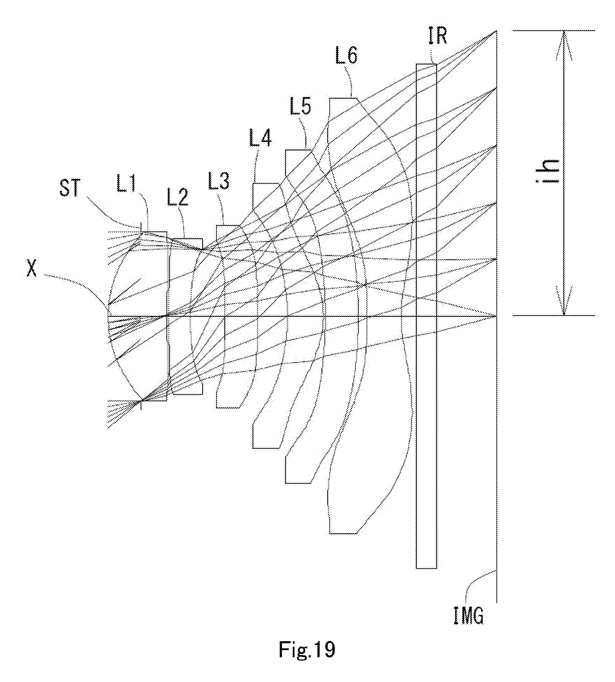
[0066] FIG. 19 is a schematic view showing the general configuration of an imaging lens in Example 10 according to the present invention;
[0067] FIG. 20 shows spherical aberration, astigmatism, and distortion of the imaging lens in Example 10 according to the present invention.
[0068] FIG. 21 is a schematic view showing the general configuration of an imaging lens in Example 11 according to the present invention;
[0069] FIG. 22 shows spherical aberration, astigmatism, and distortion of the imaging lens in Example 11 according to the present invention;
[0070] FIG. 23 is a schematic view showing the general configuration of an imaging lens in Example 12 according to the present invention; and
[0071] FIG. 24 shows spherical aberration, astigmatism, and distortion of the imaging lens in Example 12 according to the present invention.
DETAILED DESCRIPTION OF THE PREFERRED EMBODIMENT
[0072] Hereinafter, the preferred embodiments of the present invention will be described in detail referring to the accompanying drawings.
[0073] FIGS. 1, 3, 5, 7, 9, 11, 13, 15, 17, 19, 21 and 23 are schematic views of the imaging lenses in Examples 1 to 12 according to the embodiments of the present invention, respectively.
[0074] As shown in FIG. 1, the imaging lens according to the present embodiment comprises in order from an object side to an image side, a first lens L1 having positive refractive power and a convex surface facing the object side near an optical axis X, a second lens L2 having the convex surface facing the object side near the optical axis X, a third lens L3, a fourth lens L4, a fifth lens L5, and a sixth lens L6 having negative refractive power and a concave surface facing an image side near the optical axis X.
[0075] A filter IR such as an IR cut filter and a cover glass are arranged between the sixth lens L6 and an image plane IMG (namely, the image plane of an image sensor). The filter IR is omissible.
[0076] By arranging an aperture stop ST on the object side of the first lens L1, correction of aberrations and control of an incident angle of the light ray of high image height to the image sensor become facilitated.
[0077] The first lens L1 has the positive refractive power, and the wide field of view and the low-profileness are achieved by strengthening the refractive power. The shape of the first lens L1 is a meniscus shape having the convex surface facing the object side near the optical axis X, and spherical aberration and distortion are properly corrected.
[0078] The second lens L2 has the negative refractive power, and properly corrects the spherical aberration and chromatic aberration occurred at the first lens L1. A shape of the second lens L2 is the meniscus shape having the convex surface facing the object side near the optical axis X, and the chromatic aberration, the spherical aberration, astigmatism, coma aberration and field curvature are properly corrected.
[0079] The third lens L3 has the negative refractive power, and properly corrects the coma aberration, the astigmatism and the distortion. A shape of the third lens L3 is a biconcave shape having concave surfaces facing the object side and the image side near the optical axis X, and the chromatic aberration can be properly corrected. The refractive power of the third lens L3 may be positive as in Examples 9, 10, 11 and 12 shown in FIGS. 17, 19, 21 and 23. In this case, the low-profileness is more facilitated. A shape of the third lens L3 may be the meniscus shape having the convex surface facing the object side near the optical axis X as in Examples 5, 7, 8, 9 and 12 shown in FIGS. 9, 13, 15, 17 and 23. In this case, such shape is advantageous for properly correcting the astigmatism, the field curvature and the distortion. In addition, a shape of the third lens L3 may be the biconvex shape having the convex surfaces facing the object side and the image side near the optical axis X as in Examples 10 and 11 shown in FIGS. 19 and 21. In this case, the positive refractive powers of both surfaces are advantageous for the low-profileness.
[0080] The fourth lens L4 has the positive refractive power, and maintains the low-profileness and properly corrects the astigmatism, the field curvature and the distortion. A shape of the fourth lens L4 is the meniscus shape having the concave surface facing the object side near the optical axis X, therefore, the light ray incident angle to the fourth lens L4 is appropriately controlled and the chromatic aberration, the spherical aberration, the distortion and the astigmatism are properly corrected.
[0081] The fifth lens L5 has the negative refractive power, and the astigmatism, the field curvature and the distortion are properly corrected. A shape of the fifth lens L5 is the meniscus shape having the convex surface facing the object side near the optical axis X, therefore the coma aberration, the astigmatism, the field curvature and the distortion are properly corrected. A shape of the fifth lens L5 may be the meniscus shape having the concave surface facing the object side near the optical axis X as in Examples 9 and 10 shown in FIGS. 17 and 19. In this case, the light ray incident angle to the fifth lens L5 is appropriately controlled and the coma aberration and the high-order spherical aberration are properly corrected. Furthermore, the fifth lens L5 may have a shape having plane surfaces facing the object side and the image side near the optical axis X as in Example 11 and 12 shown in FIGS. 21 and 23 and substantially having no refractive power near the optical axis X. In this case, the field curvature and the distortion are properly corrected by the aspheric surfaces on both sides without affecting the focal length of the overall optical system of the imaging lens or refractive power distribution of other lenses.
[0082] The sixth lens L6 has the negative refractive power, and the chromatic aberration, the distortion, the astigmatism and the field curvature are properly corrected. A shape of the sixth lens L6 is a meniscus shape having the concave surface facing the image side near the optical axis X, therefore both of the low-profileness and the securing the back focus are realized at the same time. Furthermore, a shape of the sixth lens L6 may have a biconcave shape having concave surfaces facing the object side and the image side near the optical axis X as in Examples 9, 10 and 11 shown in FIGS. 17, 19 and 21. In this case, the negative refractive power of the both surfaces is advantageous for correcting the chromatic aberration.
[0083] The object-side surface of the sixth lens L6 has at least one off-axial pole point, and the field curvature and the distortion are properly corrected. The image-side surface of the sixth lens L6 is formed as the aspheric surface changing to the convex surface at an area apart from the optical axis X. Therefore, the back focus is secured by the negative refractive power near the optical axis X, and the light ray incident angle to the peripheral area is appropriately controlled. Thereby, the field curvature is properly corrected and the light ray incident angle to the image sensor is appropriately controlled.
[0084] Regarding the imaging lens according to the present embodiments, it is preferable that all lenses of the first lens L1 to the sixth lens L6 are single lenses. Configuration only with the single lenses can frequently use the aspheric surfaces. In the present embodiments, both-side surfaces of all lenses are formed as appropriate aspheric surfaces, and the aberrations are favorably corrected. Furthermore, workload for cementing is not required, and manufacturing in low cost becomes realizable.
[0085] The imaging lens according to the present embodiments shows preferable effect by satisfying the below conditional expressions (1) to (18).
-3.00<(D2/f2).times.100<-0.05 (1)
0.25<(T4/f).times.100<1.00 (2)
0.15<vd5/vd6<0.70 (3)
-0.36<f1/f2<0.00 (4)
0.4<(T3/f).times.100<14.0 (5)
-77.0<f2/f<-1.4 (6)
1<|f3|/f<20 (7)
0.1<r1/r2<0.6 (8)
0.5<r3/r4<3.0 (9)
0.4<|r2|/f<2.6 (10)
0.25<r3/f<2.50 (11)
f3456/f<-1.5 (12)
0.4<f1/f4<2.1 (13)
0.4<f4/f<2.0 (14)
10<T2/T4<38 (15)
where vd5: abbe number at d-ray of the fifth lens L5, vd6: abbe number at d-ray of the sixth lens L6, D2: thickness along the optical axis X of the second lens L2, T2: distance along the optical axis X from the image-side surface of the second lens L2 to the object-side surface of the third lens L3, T3: distance along the optical axis X from the image-side surface of the third lens L3 to the object-side surface of the fourth lens L4, T4: distance along the optical axis X from the image-side surface of the fourth lens L4 to the object-side surface of the fifth lens L5, f: focal length of the overall optical system of the imaging lens, f1: focal length of the first lens L1, f2: focal length of the second lens L2, f3: focal length of the third lens L3, f4: focal length of the fourth lens L4, f3456: composite focal length of the third lens L3, the fourth lens L4, the fifth lens L5 and the sixth lens L6, r1: paraxial curvature radius of the object-side surface of the first lens L1, r2: paraxial curvature radius of the image-side surface of the first lens L1, r3: paraxial curvature radius of the object-side surface of the second lens L2, and r4: paraxial curvature radius of the image-side surface of the second lens L2.
[0086] It is not necessary to satisfy the above all conditional expressions, and by satisfying the conditional expression individually, operational advantage corresponding to each conditional expression can be obtained.
[0087] The imaging lens according to the present embodiments shows further preferable effect by satisfying the below conditional expressions (1a) to (15a).
-2.50<(D2/f2).times.100<-0.10 (1a)
0.38<(T4/1).times.100<0.94 (2a)
0.25<vd5/vd6<0.60 (3a)
-0.32<f1/f2<-0.01 (4a)
0.6<(T3/f).times.100<12.0 (5a)
-64.0<f2/f<-2.1 (6a)
1.8<|f3|/f<17.0 (7a)
0.17<r1/r2<0.50 (8a)
0.8<r3/r4<2.5 (9a)
0.6<|r2|/f<2.2 (10a)
0.4<r3/f<2.1 (11a)
-80.0<f3456/f<-2.3 (12a)
0.6<f1/f4<1.7 (13a)
0.55<f4/f<1.65 (14a)
11<T2/T4<32 (15a)
[0088] The signs in the above conditional expressions have the same meanings as those in the paragraph before the preceding paragraph.
[0089] In this embodiment, the aspheric shapes of the surfaces of the aspheric lens are expressed by Equation 1, where Z denotes an axis in the optical axis direction, H denotes a height in a direction perpendicular to the optical axis, R denotes a paraxial curvature radius, k denotes a conic constant, and A4, A6, A8, A10, A12, A14 and A16 denote aspheric surface coefficients.
Z = H 2 R 1 + 1 - ( k + 1 ) H 2 R 2 + A 4 H 4 + A 6 H 6 + A 8 H 8 + A 10 H 10 + A 12 H 12 + A 14 H 14 + A 16 H 16 [ Equation 1 ] ##EQU00001##
[0090] Next, examples of the imaging lens according to this embodiment will be explained. In each example, f denotes the focal length of the overall optical system of the imaging lens, Fno denotes a F-number, w denotes a half field of view, ih denotes a maximum image height, and TTL denotes a total track length. Additionally, i denotes surface number counted from the object side, r denotes a curvature radius, d denotes the distance of lenses along the optical axis (surface distance), Nd denotes a refractive index at d-ray (reference wavelength), and vd denotes an abbe number at d-ray. As for aspheric surfaces, an asterisk (*) is added after surface number i.
Example 1
[0091] The basic lens data is shown below in Table 1.
TABLE-US-00001 TABLE 1 Example 1 Unit mm f = 3.90 Fno = 1.7 .omega.(.degree.) = 38.9 ih = 3.24 TTL = 4.86 Surface Data Surface Curvature Surface Refractive Abbe Number i Radius r Distance d Index Nd Number .nu.d (Object) Infinity Infinity 1 (Stop) Infinity -0.4030 2* 1.5960 0.7038 1.544 55.86 (.nu.d1) 3* 5.1942 0.0250 4* 3.1571 0.2597 1.661 20.37 (.nu.d2) 5* 2.9826 0.3981 6* -7.6760 0.5112 1.661 20.37 (.nu.d3) 7* 46.2555 0.0315 8* -7.7993 0.8810 1.535 55.66 (.nu.d4) 9* -1.5694 0.0237 10* 9.6181 0.4720 1.614 25.58 (.nu.d5) 11* 4.6944 0.2135 12* 3.1943 0.3984 1.535 55.66 (.nu.d6) 13* 1.2385 0.4000 14 Infinity 0.2100 1.517 64.20 15 Infinity 0.4203 Image Plane Infinity Constituent Lens Data Lens Start Surface Focal Length Composite Focal Length 1 2 3.960 f3456 -12.126 2 4 -200.226 3 6 -9.926 4 8 3.505 5 10 -15.495 6 12 -4.071 Aspheric Surface Data Second Surface Third Surface Fourth Surface Fifth Surface Sixth Surface Seventh Surface k 0.000000E+00 0.000000E+00 0.000000E+00 0.000000E+00 0.000000E+00 0.000000E+00 A4 -2.494665E-02 -4.581553E-01 -5.019561E-01 -4.514179E-02 1.438016E-02 -2.181993E-01 A6 8.304486E-02 1.445158E+00 1.697561E+00 -1.454529E-01 -1.123926E+00 3.367773E-01 A8 -1.260111E-01 -2.893413E+00 -3.662439E+00 1.337110E+00 4.313934E+00 -3.629079E-01 A10 3.123637E-02 3.638223E+00 5.122767E+00 -3.932004E+00 -9.720037E+00 3.370235E-01 A12 1.064494E-01 -2.834445E+00 -4.401046E+00 6.044746E+00 1.239320E+01 -2.540359E-01 A14 -1.147413E-01 1.233305E+00 2.101800E+00 -4.811157E+00 -8.403366E+00 1.241646E-01 A16 3.165236E-02 -2.270743E-01 -4.114485E-01 1.587729E+00 2.358892E+00 -2.347958E-02 Eighth Surface Ninth Surface Tenth Surface Eleventh Surface Twelfth Surface Thirteenth Surface k 0.000000E+00 -4.947315E+00 -1.000000E+00 -1.000000E+00 0.000000E+00 -6.732601E+00 A4 -1.431157E-01 -3.578346E-02 1.382275E-01 8.114440E-02 -4.097057E-01 -1.902676E-01 A6 3.142446E-01 -1.018883E-01 -3.827975E-01 -2.250621E-01 2.351973E-01 9.680195E-02 A8 -1.223166E-01 1.515170E-01 3.341578E-01 1.635119E-01 -7.005059E-02 -2.479085E-02 A10 -1.657864E-01 -8.690041E-02 -1.777582E-01 -7.143163E-02 1.224156E-02 3.224974E-03 A12 2.041325E-01 3.666581E-02 5.154788E-02 1.949028E-02 -1.256181E-03 -1.719901E-04 A14 -8.438109E-02 -1.007485E-02 -6.656163E-03 -2.982469E-03 6.939057E-05 -1.412879E-06 A16 1.214161E-02 1.154912E-03 2.328801E-04 1.931160E-04 -1.578511E-06 3.229464E-07
[0092] The imaging lens in Example 1 satisfies conditional expressions (1) to (15) as shown in Table 13.
[0093] FIG. 2 shows spherical aberration (mm), astigmatism (mm), and distortion (%) of the imaging lens in Example 1. The spherical aberration diagram shows the amount of aberration at wavelengths of F-ray (486 nm), d-ray (588 nm), and C-ray (656 nm). The astigmatism diagram shows the amount of aberration at d-ray on a sagittal image surface S (solid line) and on tangential image surface T (broken line), respectively (same as FIGS. 4, 6, 8, 10, 12, 14, 16, 18, 20, 22 and 24).
Example 2
[0094] The basic lens data is shown below in Table 2.
TABLE-US-00002 TABLE 2 Example 2 Unit mm f = 3.90 Fno = 1.7 .omega.(.degree.) = 39.0 ih = 3.24 TTL = 4.91 Surface Data Surface Curvature Surface Refractive Abbe Number i Radius r Distance d Index Nd Number .nu.d (Object) Infinity Infinity 1 (Stop) Infinity -0.4019 2* 1.6350 0.7292 1.544 55.86 (.nu.d1) 3* 5.7021 0.0251 4* 5.2817 0.2100 1.661 20.37 (.nu.d2) 5* 4.7295 0.4860 6* -10.7171 0.5200 1.661 20.37 (.nu.d3) 7* 53.3091 0.0530 8* -5.0641 0.8208 1.535 55.66 (.nu.d4) 9* -1.3275 0.0200 10* 9.3047 0.4402 1.614 25.58 (.nu.d5) 11* 3.1645 0.2478 12* 2.9756 0.3982 1.535 55.66 (.nu.d6) 13* 1.2591 0.4000 14 Infinity 0.2100 1.517 64.20 15 Infinity 0.4224 Image Plane Infinity Constituent Lens Data Lens Start Surface Focal Length Composite Focal Length 1 2 3.961 f3456 -16.204 2 4 -80.668 3 6 -13.461 4 8 3.125 5 10 -8.026 6 12 -4.440 Aspheric Surface Data Second Surface Third Surface Fourth Surface Fifth Surface Sixth Surface Seventh Surface k 0.000000E+00 0.000000E+00 0.000000E+00 0.000000E+00 0.000000E+00 0.000000E+00 A4 2.219251E-02 -2.976772E-01 -3.056814E-01 -3.452550E-02 -1.649320E-01 -2.494229E-01 A6 -1.212770E-01 5.444987E-01 6.379732E-01 -6.735155E-03 3.645910E-01 5.057084E-01 A8 3.701759E-01 -6.287588E-01 -8.156447E-01 3.745740E-01 -1.771822E+00 -6.910521E-01 A10 -6.521270E-01 4.518719E-01 8.136551E-01 -8.620695E-01 4.361607E+00 4.768979E-01 A12 6.415483E-01 -2.364737E-01 -6.468779E-01 9.230198E-01 -6.191618E+00 -1.309076E-01 A14 -3.353906E-01 8.961423E-02 3.539939E-01 -4.606896E-01 4.638928E+00 -1.238421E-02 A16 6.916489E-02 -1.674795E-02 -8.341943E-02 7.676398E-02 -1.432825E+00 1.095139E-02 Eighth Surface Ninth Surface Tenth Surface Eleventh Surface Twelfth Surface Thirteenth Surface k 0.000000E+00 -4.564791E+00 -1.000000E+00 -1.000000E+00 0.000000E+00 -6.518657E+00 A4 -2.560977E-01 -2.327232E-02 1.542401E-01 1.201724E-02 -4.057406E-01 -1.934956E-01 A6 8.167351E-01 -1.168705E-01 -3.737136E-01 -1.418516E-01 2.332138E-01 1.063440E-01 A8 -1.216382E+00 1.748212E-01 3.201396E-01 1.044357E-01 -7.129138E-02 -3.201358E-02 A10 1.061007E+00 -1.188553E-01 -1.690332E-01 -4.287407E-02 1.310337E-02 5.728403E-03 A12 -5.317915E-01 5.464838E-02 5.144540E-02 1.059235E-02 -1.464649E-03 -6.109739E-04 A14 1.411584E-01 -1.503413E-02 -8.221265E-03 -1.446448E-03 9.236738E-05 3.639795E-05 A16 -1.541334E-02 1.694523E-03 5.506661E-04 8.330305E-05 -2.548786E-06 -9.473625E-07
[0095] The imaging lens in Example 2 satisfies conditional expressions (1) to (15) as shown in Table 13.
[0096] FIG. 4 shows the spherical aberration (mm), the astigmatism (mm), and the distortion (%) of the imaging lens in Example 2.
Example 3
[0097] The basic lens data is shown below in Table 3.
TABLE-US-00003 TABLE 3 Example 3 Unit mm f = 3.91 Fno = 1.7 .omega.(.degree.) = 39.0 ih = 3.24 TTL = 4.91 Surface Data Surface Curvature Surface Refractive Abbe Number i Radius r Distance d Index Nd Number .nu.d (Object) Infinity Infinity 1 (Stop) Infinity -0.4148 2* 1.6175 0.7137 1.544 55.86 (.nu.d1) 3* 5.7426 0.0252 4* 5.1349 0.2100 1.661 20.37 (.nu.d2) 5* 4.2356 0.5015 6* -14.9483 0.4384 1.661 20.37 (.nu.d3) 7* 72.0036 0.0504 8* -4.7552 0.9477 1.535 55.66 (.nu.d4) 9* -1.4215 0.0200 10* 4.7700 0.3658 1.614 25.58 (.nu.d5) 11* 2.6400 0.2782 12* 3.0573 0.3993 1.535 55.66 (.nu.d6) 13* 1.2552 0.4000 14 Infinity 0.2100 1.517 64.20 15 Infinity 0.4232 Image Plane Infinity Constituent Lens Data Lens Start Surface Focal Length Composite Focal Length 1 2 3.899 f3456 -19.583 2 4 -40.351 3 6 -18.697 4 8 3.450 5 10 -10.298 6 12 -4.315 Aspheric Surface Data Second Surface Third Surface Fourth Surface Fifth Surface Sixth Surface Seventh Surface k 0.000000E+00 0.000000E+00 0.000000E+00 0.000000E+00 0.000000E+00 0.000000E+00 A4 1.675830E-02 -3.075204E-01 -3.110407E-01 -4.184615E-02 -1.744960E-01 -1.955987E-01 A6 -9.131112E-02 6.868693E-01 7.592557E-01 1.000237E-01 4.125112E-01 3.715015E-01 A8 2.972311E-01 -1.091956E+00 -1.266736E+00 -7.685139E-02 -2.028268E+00 -5.593222E-01 A10 -5.459363E-01 1.232890E+00 1.639565E+00 1.504258E-01 5.004237E+00 4.026639E-01 A12 5.519330E-01 -9.653794E-01 -1.480384E+00 -3.446050E-01 -7.110474E+00 -1.033344E-01 A14 -2.927886E-01 4.459986E-01 7.938588E-01 3.763308E-01 5.324747E+00 -2.033619E-02 A16 6.020633E-02 -8.829163E-02 -1.784782E-01 -1.507638E-01 -1.640728E+00 1.290651E-02 Eighth Surface Ninth Surface Tenth Surface Eleventh Surface Twelfth Surface Thirteenth Surface k 0.000000E+00 -5.119861E+00 -1.000000E+00 -1.000000E+00 0.000000E+00 -6.492679E+00 A4 -1.637552E-01 -7.038125E-02 9.546600E-02 5.588236E-03 -4.164567E-01 -1.977020E-01 A6 5.865762E-01 -4.426055E-02 -3.013795E-01 -1.675713E-01 2.422150E-01 1.105875E-01 A8 -9.429588E-01 9.965855E-02 2.517653E-01 1.360497E-01 -7.382361E-02 -3.312239E-02 A10 8.842064E-01 -6.154976E-02 -1.185440E-01 -6.134956E-02 1.338864E-02 5.821833E-03 A12 -4.704424E-01 2.456451E-02 2.731154E-02 1.631496E-02 -1.462763E-03 -6.040631E-04 A14 1.310370E-01 -6.155751E-03 -1.963429E-03 -2.343932E-03 8.938939E-05 3.465772E-05 A16 -1.497701E-02 6.450635E-04 -1.128505E-04 1.393502E-04 -2.368584E-06 -8.599661E-07
[0098] The imaging lens in Example 3 satisfies conditional expressions (1) to (15) as shown in Table 13.
[0099] FIG. 6 shows the spherical aberration (mm), the astigmatism (mm), and the distortion (%) of the imaging lens in Example 3.
Example 4
[0100] The basic lens data is shown below in Table 4.
TABLE-US-00004 TABLE 4 Example 4 Unit mm f = 3.91 Fno = 1.7 .omega.(.degree.) = 39.0 ih = 3.24 TTL = 4.91 Surface Data Surface Curvature Surface Refractive Abbe Number i Radius r Distance d Index Nd Number .nu.d (Object) Infinity Infinity 1 (Stop) Infinity -0.3300 2* 1.6360 0.7606 1.544 55.86 (.nu.d1) 3* 6.7713 0.0250 4* 5.3935 0.2100 1.661 20.37 (.nu.d2) 5* 3.7807 0.4354 6* -42.5885 0.4772 1.661 20.37 (.nu.d3) 7* 129.0590 0.0587 8* -4.0201 0.9046 1.535 55.66 (.nu.d4) 9* -1.3487 0.0200 10* 4.5977 0.3500 1.614 25.58 (.nu.d5) 11* 2.2123 0.3249 12* 2.8962 0.3900 1.535 55.66 (.nu.d6) 13* 1.2921 0.4000 14 Infinity 0.2100 1.517 64.20 15 Infinity 0.4163 Image Plane Infinity Constituent Lens Data Lens Start Surface Focal Length Composite Focal Length 1 2 3.767 f3456 -28.722 2 4 -20.181 3 6 -48.409 4 8 3.395 5 10 -7.353 6 12 -4.766 Aspheric Surface Data Second Surface Third Surface Fourth Surface Fifth Surface Sixth Surface Seventh Surface k 0.000000E+00 0.000000E+00 0.000000E+00 0.000000E+00 0.000000E+00 0.000000E+00 A4 1.314854E-02 -3.613569E-01 -3.794969E-01 -6.410773E-02 -1.534905E-01 -2.125438E-01 A6 -5.682942E-02 9.936721E-01 1.061752E+00 6.272260E-02 1.877188E-01 4.551382E-01 A8 1.668851E-01 -1.719659E+00 -1.787632E+00 4.529589E-01 -8.541968E-01 -7.959582E-01 A10 -2.768910E-01 1.936687E+00 2.023345E+00 -1.589295E+00 1.720304E+00 7.045416E-01 A12 2.533550E-01 -1.431532E+00 -1.497351E+00 2.427362E+00 -2.069428E+00 -2.884780E-01 A14 -1.210188E-01 6.183792E-01 6.517456E-01 -1.837758E+00 1.281047E+00 2.111336E-02 A16 2.075327E-02 -1.159321E-01 -1.166212E-01 5.702602E-01 -3.099234E-01 1.435418E-02 Eighth Surface Ninth Surface Tenth Surface Eleventh Surface Twelfth Surface Thirteenth Surface k 0.000000E+00 -5.181441E+00 -1.000000E+00 -1.000000E+00 0.000000E+00 -6.330310E+00 A4 -1.864116E-01 -9.314452E-02 4.740399E-02 -6.428117E-02 -3.972425E-01 -1.925412E-01 A6 7.268569E-01 7.195772E-03 -2.529879E-01 -7.909205E-02 2.148717E-01 1.003552E-01 A8 -1.330793E+00 3.639762E-02 2.237765E-01 7.115787E-02 -6.237913E-02 -3.115335E-02 A10 1.427642E+00 -2.514733E-02 -1.255168E-01 -3.013285E-02 1.103730E-02 5.978580E-03 A12 -8.730578E-01 1.758129E-02 4.510762E-02 7.182004E-03 -1.210867E-03 -7.004774E-04 A14 2.810034E-01 -7.665171E-03 -1.041374E-02 -9.062191E-04 7.666617E-05 4.682143E-05 A16 -3.692293E-02 1.180040E-03 1.181161E-03 4.703129E-05 -2.182116E-06 -1.390026E-06
[0101] The imaging lens in Example 4 satisfies conditional expressions (1) to (15) as shown in Table 13.
[0102] FIG. 8 shows the spherical aberration (mm), the astigmatism (mm), and the distortion (%) of the imaging lens in Example 4.
Example 5
[0103] The basic lens data is shown below in Table 5.
TABLE-US-00005 TABLE 5 Example 5 Unit mm f = 3.93 Fno = 1.7 .omega.(.degree.) = 38.9 ih = 3.24 TTL = 4.75 Surface Data Surface Curvature Surface Refractive Abbe Number i Radius r Distance d Index Nd Number .nu.d (Object) Infinity Infinity 1 (Stop) Infinity -0.4898 2* 1.5081 0.6956 1.497 81.56 (.nu.d1) 3* 4.4484 0.0250 4* 2.3172 0.2862 1.661 20.37 (.nu.d2) 5* 2.1650 0.4495 6* 27.6538 0.2200 1.661 20.37 (.nu.d3) 7* 11.2028 0.0488 8* -4.7203 1.0714 1.535 55.66 (.nu.d4) 9* -1.4352 0.0341 10* 7.6514 0.3502 1.614 25.58 (.nu.d5) 11* 4.1444 0.2653 12* 7.2357 0.3938 1.535 55.66 (.nu.d6) 13* 1.4161 0.4000 14 Infinity 0.2100 1.517 64.20 15 Infinity 0.3720 Image Plane Infinity Constituent Lens Data Lens Start Surface Focal Length Composite Focal Length 1 2 4.256 f3456 -14.925 2 4 -198.497 3 6 -28.653 4 8 3.463 5 10 -15.302 6 12 -3.372 Aspheric Surface Data Second Surface Third Surface Fourth Surface Fifth Surface Sixth Surface Seventh Surface k 0.000000E+00 0.000000E+00 0.000000E+00 0.000000E+00 0.000000E+00 0.000000E+00 A4 -4.320831E-02 -2.553746E-01 -2.541814E-01 -2.873361E-02 -7.606895E-02 -1.463918E-01 A6 2.013111E-01 7.794711E-01 8.289962E-01 1.195416E-01 -8.194382E-01 1.057962E-01 A8 -4.827703E-01 -1.620662E+00 -1.941274E+00 -2.887159E-01 2.891252E+00 -6.565240E-01 A10 6.662979E-01 2.199911E+00 2.963705E+00 3.675267E-01 -6.755415E+00 1.409561E+00 A12 -5.281275E-01 -1.859366E+00 -2.752774E+00 -5.155795E-02 8.881318E+00 -1.639228E+00 A14 2.242762E-01 8.731784E-01 1.394164E+00 -3.546526E-01 -6.594661E+00 9.663928E-01 A16 -4.082081E-02 -1.718792E-01 -2.808483E-01 2.582897E-01 2.194995E+00 -2.033226E-01 Eighth Surface Ninth Surface Tenth Surface Eleventh Surface Twelfth Surface Thirteenth Surface k 0.000000E+00 -6.665829E+00 -1.000000E+00 -1.000000E+00 0.000000E+00 -9.684518E+00 A4 1.984946E-02 -2.395451E-01 2.098548E-02 -3.919250E-03 -4.968877E-01 -2.352121E-01 A6 -9.550050E-02 2.123476E-01 -2.836738E-01 -2.193413E-01 3.614903E-01 1.551896E-01 A8 2.228116E-01 -2.065946E-01 2.858493E-01 2.122612E-01 -1.306396E-01 -5.621320E-02 A10 -1.723669E-01 1.829152E-01 -1.616862E-01 -1.100322E-01 2.749315E-02 1.172827E-02 A12 6.275359E-02 -8.603633E-02 4.699812E-02 3.383471E-02 -3.414733E-03 -1.410254E-03 A14 -1.016701E-02 1.958032E-02 -5.725752E-03 -5.737454E-03 2.329653E-04 9.187881E-05 A16 1.307597E-04 -1.812259E-03 1.528488E-04 4.102837E-04 -6.761688E-06 -2.540851E-06
[0104] The imaging lens in Example 5 satisfies conditional expressions (1) to (15) as shown in Table 13.
[0105] FIG. 10 shows the spherical aberration (mm), the astigmatism (mm), and the distortion (%) of the imaging lens in Example 5.
Example 6
[0106] The basic lens data is shown below in Table 6.
TABLE-US-00006 TABLE 6 Example 6 Unit mm f = 3.93 Fno = 1.7 .omega.(.degree.) = 39.0 ih = 3.24 TTL = 4.88 Surface Data Surface Curvature Surface Refractive Abbe Number i Radius r Distance d Index Nd Number .nu.d (Object) Infinity Infinity 1 (Stop) Infinity -0.4479 2* 1.5581 0.6843 1.497 81.56 (.nu.d1) 3* 4.9704 0.0540 4* 2.6119 0.2568 1.661 20.37 (.nu.d2) 5* 2.3920 0.4992 6* -64.7029 0.2321 1.661 20.37 (.nu.d3) 7* 18.3177 0.0376 8* -5.5061 1.1327 1.535 55.66 (.nu.d4) 9* -1.3844 0.0200 10* 5.5299 0.3500 1.614 25.58 (.nu.d5) 11* 3.2266 0.2881 12* 5.6973 0.3930 1.535 55.66 (.nu.d6) 13* 1.3515 0.4000 14 Infinity 0.2100 1.517 64.20 15 Infinity 0.3924 Image Plane Infinity Constituent Lens Data Lens Start Surface Focal Length Composite Focal Length 1 2 4.281 f3456 -23.251 2 4 -80.355 3 6 -21.582 4 8 3.156 5 10 -13.386 6 12 -3.421 Aspheric Surface Data Second Surface Third Surface Fourth Surface Fifth Surface Sixth Surface Seventh Surface k 0.000000E+00 0.000000E+00 0.000000E+00 0.000000E+00 0.000000E+00 0.000000E+00 A4 -9.576577E-04 -8.612158E-02 -1.128938E-01 -1.265846E-02 -1.656441E-01 -1.525781E-01 A6 7.597136E-03 1.067812E-01 1.748749E-01 -9.918292E-02 -1.365393E-01 8.718087E-02 A8 4.878714E-02 1.950668E-02 -2.504269E-01 5.143221E-01 7.598084E-02 -3.461927E-01 A10 -1.577285E-01 -3.033710E-01 2.207419E-01 -1.369087E+00 4.381539E-04 5.951410E-01 A12 2.124231E-01 4.856570E-01 -5.959169E-02 2.015918E+00 -2.747268E-01 -6.148588E-01 A14 -1.331060E-01 -3.528775E-01 -7.148393E-02 -1.602500E+00 4.115225E-02 3.369072E-01 A16 3.225283E-02 1.037860E-01 5.693187E-02 5.329208E-01 1.616786E-01 -6.152292E-02 Eighth Surface Ninth Surface Tenth Surface Eleventh Surface Twelfth Surface Thirteenth Surface k 0.000000E+00 -6.862341E+00 -1.000000E+00 -1.000000E+00 0.000000E+00 -7.995719E+00 A4 -1.040185E-02 -2.179050E-01 3.686707E-02 -6.730511E-03 -4.414291E-01 -2.160280E-01 A6 7.032637E-02 1.542568E-01 -2.864858E-01 -1.998678E-01 2.859566E-01 1.345931E-01 A8 -1.304021E-01 -9.560601E-02 2.846573E-01 1.796475E-01 -9.283490E-02 -4.506725E-02 A10 1.820369E-01 5.808862E-02 -1.617493E-01 -8.715998E-02 1.772127E-02 8.691762E-03 A12 -1.261264E-01 -1.663503E-02 4.978304E-02 2.496474E-02 -2.015461E-03 -9.665006E-04 A14 4.102473E-02 1.151643E-03 -7.474335E-03 -3.901785E-03 1.268660E-04 5.800060E-05 A16 -5.224471E-03 1.226775E-04 4.297330E-04 2.549957E-04 -3.416146E-06 -1.467137E-06
[0107] The imaging lens in Example 6 satisfies conditional expressions (1) to (15) as shown in Table 13.
[0108] FIG. 12 shows the spherical aberration (mm), the astigmatism (mm), and the distortion (%) of the imaging lens in Example 6.
Example 7
[0109] The basic lens data is shown below in Table 7.
TABLE-US-00007 TABLE 7 Example 7 Unit mm f = 3.93 Fno = 1.7 .omega.(.degree.) = 39.0 ih = 3.24 TTL = 4.91 Surface Data Surface Curvature Surface Refractive Abbe Number i Radius r Distance d Index Nd Number .nu.d (Object) Infinity Infinity 1 (Stop) Infinity -0.4558 2* 1.5983 0.6686 1.497 81.56 (.nu.d1) 3* 5.5495 0.1034 4* 2.5398 0.2250 1.661 20.37 (.nu.d2) 5* 2.2368 0.4863 6* 2319.3650 0.2385 1.661 20.37 (.nu.d3) 7* 16.1474 0.0340 8* -6.2979 1.1376 1.535 55.66 (.nu.d4) 9* -1.5003 0.0200 10* 3.8417 0.3500 1.614 25.58 (.nu.d5) 11* 2.7569 0.3298 12* 6.5607 0.3900 1.535 55.66 (.nu.d6) 13* 1.4163 0.4000 14 Infinity 0.2100 1.517 64.20 15 Infinity 0.3847 Image Plane Infinity Constituent Lens Data Lens Start Surface Focal Length Composite Focal Length 1 2 4.276 f3456 -35.834 2 4 -40.279 3 6 -24.610 4 8 3.401 5 10 -18.121 6 12 -3.469 Aspheric Surface Data Second Surface Third Surface Fourth Surface Fifth Surface Sixth Surface Seventh Surface k 0.000000E+00 0.000000E+00 0.000000E+00 0.000000E+00 0.000000E+00 0.000000E+00 A4 1.414196E-02 -5.908402E-02 -1.042727E-01 -4.727647E-02 -2.195640E-01 -1.527542E-01 A6 -6.279461E-02 6.166831E-02 1.028652E-01 -1.204417E-02 2.720215E-01 1.231177E-01 A8 2.124842E-01 -1.264154E-02 -1.688104E-01 8.306197E-02 -1.498241E+00 -4.396790E-01 A10 -3.761985E-01 -7.696124E-02 2.824368E-01 -1.496464E-01 3.579108E+00 7.314785E-01 A12 3.758662E-01 1.380013E-01 -2.976880E-01 1.322184E-01 -4.917173E+00 -7.341920E-01 A14 -1.973559E-01 -1.085873E-01 1.567226E-01 -9.071103E-02 3.299050E+00 3.955091E-01 A16 4.256947E-02 3.567244E-02 -2.059205E-02 3.467685E-02 -8.097551E-01 -7.514232E-02 Eighth Surface Ninth Surface Tenth Surface Eleventh Surface Twelfth Surface Thirteenth Surface k 0.000000E+00 -9.919037E+00 -1.000000E+00 -1.000000E+00 0.000000E+00 -8.549199E+00 A4 6.541012E-03 -2.637794E-01 1.126527E-02 -3.085958E-02 -4.470929E-01 -2.133378E-01 A6 8.080227E-02 2.531796E-01 -2.518394E-01 -1.654612E-01 2.962967E-01 1.330046E-01 A8 -1.797721E-01 -2.102118E-01 2.641382E-01 1.538849E-01 -9.810283E-02 -4.382435E-02 A10 2.269472E-01 1.469179E-01 -1.566773E-01 -7.571827E-02 1.912306E-02 8.335375E-03 A12 -1.446858E-01 -5.870899E-02 5.110349E-02 2.183111E-02 -2.224953E-03 -9.192412E-04 A14 4.491997E-02 1.167322E-02 -8.454110E-03 -3.420349E-03 1.434995E-04 5.495167E-05 A16 -5.486636E-03 -9.258210E-04 5.637976E-04 2.238461E-04 -3.963877E-06 -1.388793E-06
[0110] The imaging lens in Example 7 satisfies conditional expressions (1) to (15) as shown in Table 13.
[0111] FIG. 14 shows the spherical aberration (mm), the astigmatism (mm), and the distortion (%) of the imaging lens in Example 7.
Example 8
[0112] The basic lens data is shown below in Table 8.
TABLE-US-00008 TABLE 8 Example 8 Unit mm f = 3.93 Fno = 1.7 .omega.(.degree.) = 39.0 ih = 3.24 TTL = 4.91 Surface Data Surface Curvature Surface Refractive Abbe Number i Radius r Distance d Index Nd Number .nu.d (Object) Infinity Infinity 1 (Stop) Infinity -0.4614 2* 1.6253 0.6591 1.497 81.56 (.nu.d1) 3* 6.6760 0.1337 4* 2.6379 0.2138 1.661 20.37 (.nu.d2) 5* 2.1310 0.4785 6* 25.8099 0.2200 1.661 20.37 (.nu.d3) 7* 14.7258 0.0926 8* -5.8668 1.0900 1.535 55.66 (.nu.d4) 9* -1.4797 0.0200 10* 3.6758 0.3500 1.614 25.58 (.nu.d5) 11* 2.5817 0.3385 12* 6.6705 0.3900 1.535 55.66 (.nu.d6) 13* 1.4431 0.4000 14 Infinity 0.2100 1.517 64.20 15 Infinity 0.3850 Image Plane Infinity Constituent Lens Data Lens Start Surface Focal Length Composite Focal Length 1 2 4.142 f3456 -198.955 2 4 -20.164 3 6 -52.308 4 8 3.405 5 10 -16.078 6 12 -3.535 Aspheric Surface Data Second Surface Third Surface Fourth Surface Fifth Surface Sixth Surface Seventh Surface k 0.000000E+00 0.000000E+00 0.000000E+00 0.000000E+00 0.000000E+00 0.000000E+00 A4 7.800591E-03 -3.407840E-02 -8.582655E-02 -7.414399E-02 -2.192804E-01 -1.164428E-01 A6 -2.995095E-02 3.452281E-02 4.602065E-02 1.337299E-01 3.279950E-01 -4.351808E-03 A8 1.130016E-01 -2.705391E-02 -4.535713E-02 -5.309232E-01 -1.752863E+00 -2.659374E-01 A10 -2.113084E-01 3.353857E-02 1.421641E-01 1.374112E+00 4.011543E+00 5.940008E-01 A12 2.195444E-01 -3.601320E-02 -2.344296E-01 -2.011554E+00 -5.182123E+00 -5.613685E-01 A14 -1.187062E-01 1.663238E-02 1.767484E-01 1.514661E+00 3.251317E+00 3.504071E-01 A16 2.629057E-02 -4.702911E-05 -4.292545E-02 -4.668060E-01 -7.422448E-01 -5.727064E-02 Eighth Surface Ninth Surface Tenth Surface Eleventh Surface Twelfth Surface Thirteenth Surface k 0.000000E+00 -1.033070E+01 -1.000000E+00 -1.000000E+00 0.000000E+00 -8.436097E+00 A4 4.365146E-02 -2.689348E-01 1.309667E-02 -3.433698E-02 -4.218126E-01 -2.060269E-01 A6 -5.149894E-02 2.589878E-01 -2.562820E-01 -1.602079E-01 2.722397E-01 1.248024E-01 A8 4.288288E-02 -2.146251E-01 2.640474E-01 1.481908E-01 -8.785701E-02 -3.987145E-02 A10 1.432960E-02 1.465054E-01 -1.511793E-01 -7.183349E-02 1.670611E-02 7.373240E-03 A12 -2.821755E-02 -5.730216E-02 4.728609E-02 2.024662E-02 -1.897844E-03 -7.925936E-04 A14 1.111792E-02 1.122004E-02 -7.469936E-03 -3.086935E-03 1.196389E-04 4.625844E-05 A16 -1.454335E-03 -8.767736E-04 4.727198E-04 1.962747E-04 -3.234387E-06 -1.142943E-06
[0113] The imaging lens in Example 8 satisfies conditional expressions (1) to (15) as shown in Table 13.
[0114] FIG. 16 shows the spherical aberration (mm), the astigmatism (mm), and the distortion (%) of the imaging lens in Example 8.
Example 9
[0115] The basic lens data is shown below in Table 9.
TABLE-US-00009 TABLE 9 Example 9 Unit mm f = 3.44 Fno = 1.8 .omega.(.degree.) = 39.3 ih = 2.90 TTL = 3.86 Surface Data Surface Curvature Surface Refractive Abbe Number i Radius r Distance d Index Nd Number .nu.d (Object) Infinity Infinity 1 (Stop) Infinity -0.3919 2* 1.1656 0.6397 1.535 55.66 (.nu.d1) 3* 3.2584 0.0304 4* 6.5160 0.2200 1.650 21.54 (.nu.d2) 5* 3.3618 0.3075 6* 10.1821 0.3377 1.535 55.66 (.nu.d3) 7* 42.1600 0.3701 8* -2.1364 0.3005 1.535 55.66 (.nu.d4) 9* -0.9366 0.0200 10* -4.6623 0.3433 1.650 21.54 (.nu.d5) 11* -5.2630 0.0958 12* -9.5614 0.3000 1.535 55.66 (.nu.d6) 13* 1.3501 0.1508 14 Infinity 0.2100 1.517 64.20 15 Infinity 0.6018 Image Plane Infinity Constituent Lens Data Lens Start Surface Focal Length Composite Focal Length 1 2 3.067 f3456 -24.274 2 4 -10.980 3 6 25.009 4 8 2.868 5 10 -81.077 6 12 -2.191 Aspheric Surface Data Second Surface Third Surface Fourth Surface Fifth Surface Sixth Surface Seventh Surface k 0.000000E+00 0.000000E+00 0.000000E+00 0.000000E+00 0.000000E+00 0.000000E+00 A4 -2.631779E-02 -2.509354E-01 -2.485880E-01 -9.549074E-02 -2.466895E-01 -1.208887E-01 A6 8.956181E-02 -9.292390E-01 -4.844860E-01 1.355343E+00 5.964034E-01 -7.429160E-02 A8 -5.793678E-02 5.020344E+00 4.457739E+00 -5.225218E+00 -4.042058E+00 -4.741214E-01 A10 -3.758986E-01 -9.283742E+00 -9.271641E+00 1.593274E+01 1.170946E+01 1.492990E+00 A12 8.257866E-01 7.783348E+00 8.560745E+00 -2.592894E+01 -1.716099E+01 -2.490921E+00 A14 -5.735678E-01 -2.552656E+00 -2.927530E+00 1.795061E+01 9.905019E+00 2.067112E+00 A16 0.000000E+00 0.000000E+00 0.000000E+00 0.000000E+00 0.000000E+00 -5.970312E-01 Eighth Surface Ninth Surface Tenth Surface Eleventh Surface Twelfth Surface Thirteenth Surface k 0.000000E+00 -3.000000E+00 0.000000E+00 0.000000E+00 0.000000E+00 -1.100000E+01 A4 6.668551E-02 8.395808E-02 1.082630E-01 2.624611E-02 -3.108054E-01 -2.001197E-01 A6 -2.964831E-01 -5.392823E-01 -4.725258E-01 -2.083615E-01 2.619533E-01 1.728182E-01 A8 9.671528E-01 1.395428E+00 8.952806E-01 3.559073E-01 -1.085665E-01 -1.106089E-01 A10 -1.562108E+00 -1.453700E+00 -9.692357E-01 -3.109144E-01 2.791881E-02 4.463578E-02 A12 1.252321E+00 7.488013E-01 5.579658E-01 1.403916E-01 -4.569106E-03 -1.065804E-02 A14 -4.786551E-01 -1.904327E-01 -1.579464E-01 -3.096426E-02 4.379449E-04 1.353879E-03 A16 6.987180E-02 1.900546E-02 1.734364E-02 2.647354E-03 -1.860861E-05 -6.972694E-05
[0116] The imaging lens in Example 9 satisfies conditional expressions (1) to (15) as shown in Table 13.
[0117] FIG. 18 shows the spherical aberration (mm), the astigmatism (mm), and the distortion (%) of the imaging lens in Example 9.
Example 10
[0118] The basic lens data is shown below in Table 10.
TABLE-US-00010 TABLE 10 Example 10 Unit mm f = 3.44 Fno = 2.0 .omega.(.degree.) = 39.3 ih = 2.80 TTL = 3.87 Surface Data Surface Curvature Surface Refractive Abbe Number i Radius r Distance d Index Nd Number .nu.d (Object) Infinity Infinity 1 (Stop) Infinity -0.3307 2* 1.1656 0.5915 1.535 55.66 (.nu.d1) 3* 3.2584 0.0200 4* 4.2192 0.2200 1.650 21.54 (.nu.d2) 5* 2.8917 0.3502 6* 64.3687 0.3323 1.535 55.66 (.nu.d3) 7* -28.0162 0.3040 8* -1.9365 0.3653 1.535 55.66 (.nu.d4) 9* -0.8541 0.0200 10* -3.6746 0.3331 1.650 21.54 (.nu.d5) 11* -5.2942 0.0884 12* -9.0064 0.3454 1.535 55.66 (.nu.d6) 13* 1.3243 0.1508 14 Infinity 0.2100 1.517 64.20 15 Infinity 0.6084 Image Plane Infinity Constituent Lens Data Lens Start Surface Focal Length Composite Focal Length 1 2 3.089 f3456 -14.015 2 4 -15.119 3 6 36.545 4 8 2.556 5 10 -20.099 6 12 -2.134 Aspheric Surface Data Second Surface Third Surface Fourth Surface Fifth Surface Sixth Surface Seventh Surface k 0.000000E+00 0.000000E+00 0.000000E+00 0.000000E+00 0.000000E+00 0.000000E+00 A4 -1.022505E-02 -6.870573E-01 -6.217360E-01 -3.810617E-02 -2.275473E-01 -1.438132E-01 A6 2.356933E-02 1.318411E+00 1.527953E+00 7.970939E-01 3.697978E-01 9.149466E-03 A8 7.281789E-02 -9.087701E-02 -4.406743E-01 -1.796880E+00 -3.341046E+00 -1.003509E+00 A10 -5.384696E-01 -3.800909E+00 -3.538117E+00 4.732877E+00 1.086985E+01 2.470956E+00 A12 9.675580E-01 5.361136E+00 5.811253E+00 -7.977381E+00 -1.758402E+01 -3.197994E+00 A14 -7.247154E-01 -2.420149E+00 -2.722500E+00 7.291796E+00 1.138492E+01 2.003472E+00 A16 0.000000E+00 0.000000E+00 0.000000E+00 0.000000E+00 0.000000E+00 -2.874541E-01 Eighth Surface Ninth Surface Tenth Surface Eleventh Surface Twelfth Surface Thirteenth Surface k 0.000000E+00 -3.000000E+00 0.000000E+00 0.000000E+00 0.000000E+00 -1.100000E+01 A4 3.092851E-02 7.469268E-02 1.631644E-01 -1.689672E-02 -3.053348E-01 -1.838253E-01 A6 6.038460E-02 -3.792828E-01 -5.773575E-01 -1.522919E-01 2.629008E-01 1.539175E-01 A8 -2.825179E-01 8.990079E-01 1.027874E+00 3.456524E-01 -1.154200E-01 -1.006508E-01 A10 1.400840E-01 -8.283808E-01 -1.018327E+00 -3.338282E-01 3.276455E-02 4.158624E-02 A12 1.082234E-01 3.386280E-01 5.132409E-01 1.569316E-01 -6.087204E-03 -1.012698E-02 A14 -8.986417E-02 -4.906978E-02 -1.195106E-01 -3.547820E-02 6.702436E-04 1.308355E-03 A16 1.744251E-02 -1.458128E-03 9.539280E-03 3.103870E-03 -3.273933E-05 -6.843487E-05
[0119] The imaging lens in Example 10 satisfies conditional expressions (1) to (15) as shown in Table 13.
[0120] FIG. 20 shows the spherical aberration (mm), the astigmatism (mm), and the distortion (%) of the imaging lens in Example 10.
Example 11
[0121] The basic lens data is shown below in Table 11.
TABLE-US-00011 TABLE 11 Example 11 Unit mm f = 3.36 Fno = 1.9 .omega.(.degree.) = 40.4 ih = 2.90 TTL = 3.93 Surface Data Surface Curvature Surface Refractive Abbe Number i Radius r Distance d Index Nd Number .nu.d (Object) Infinity Infinity 1 (Stop) Infinity -0.3792 2* 1.2242 0.5914 1.497 81.55 (.nu.d1) 3* 3.2654 0.1744 4* 4.5104 0.2200 1.650 21.54 (.nu.d2) 5* 3.2913 0.2377 6* 11.4566 0.3561 1.535 55.66 (.nu.d3) 7* -20.5659 0.2138 8* -1.8909 0.3500 1.535 55.66 (.nu.d4) 9* -0.9940 0.0200 10* Infinity 0.2750 1.650 21.54 (.nu.d5) 11* Infinity 0.1382 12* -8.9115 0.4500 1.535 55.66 (.nu.d6) 13* 1.4807 0.1508 14 Infinity 0.2100 1.517 64.20 15 Infinity 0.6172 Image Plane Infinity Constituent Lens Data Lens Start Surface Focal Length Composite Focal Length 1 2 3.595 f3456 -177.234 2 4 -20.158 3 6 13.811 4 8 3.449 5 10 Infinity 6 12 -2.339 Aspheric Surface Data Second Surface Third Surface Fourth Surface Fifth Surface Sixth Surface Seventh Surface k 0.000000E+00 0.000000E+00 0.000000E+00 0.000000E+00 0.000000E+00 0.000000E+00 A4 2.853323E-03 -6.542153E-02 -2.346937E-01 -1.445645E-01 -1.056966E-01 -9.367614E-02 A6 9.722830E-03 1.115535E-01 4.000772E-01 1.885260E-01 -3.779418E-01 1.686798E-01 A8 -1.741557E-02 -4.093871E-01 -1.425189E+00 -5.925904E-01 1.204380E+00 -8.543157E-01 A10 7.896126E-02 9.059203E-01 3.460904E+00 2.526849E+00 -2.751107E+00 1.244950E+00 A12 -8.265374E-02 -1.047643E+00 -4.179792E+00 -4.030044E+00 3.544737E+00 -1.452755E+00 A14 4.084531E-02 4.400629E-01 1.919045E+00 2.493209E+00 -1.713108E+00 1.389702E+00 A16 0.000000E+00 0.000000E+00 0.000000E+00 0.000000E+00 0.000000E+00 -5.285055E-01 Eighth Surface Ninth Surface Tenth Surface Eleventh Surface Twelfth Surface Thirteenth Surface k 0.000000E+00 -3.000000E+00 0.000000E+00 0.000000E+00 0.000000E+00 -1.100000E+01 A4 -2.908666E-03 6.878398E-02 2.449628E-01 2.164858E-01 -9.559675E-02 -1.230986E-01 A6 1.042669E+00 1.825134E-01 -5.556753E-01 -4.458299E-01 -3.573676E-02 5.582625E-02 A8 -2.136300E+00 -1.721635E-01 3.287377E-01 2.712478E-01 8.617697E-02 -1.146591E-02 A10 1.771914E+00 -7.702910E-03 -9.215944E-02 -7.211561E-02 -4.258342E-02 -1.115224E-03 A12 -6.770531E-01 6.895284E-02 3.137494E-02 7.372614E-03 9.839882E-03 8.189923E-04 A14 1.077886E-01 -3.043831E-02 -1.227632E-02 1.476141E-04 -1.116036E-03 -1.158143E-04 A16 -4.022856E-03 3.995977E-03 1.864776E-03 -5.108027E-05 4.985992E-05 5.325158E-06
[0122] The imaging lens in Example 11 satisfies conditional expressions (1) to (15) as shown in Table 13.
[0123] FIG. 22 shows the spherical aberration (mm), the astigmatism (mm), and the distortion (%) of the imaging lens in Example 11.
Example 12
[0124] The basic lens data is shown below in Table 12.
TABLE-US-00012 TABLE 12 Example 12 Unit mm f = 3.47 Fno = 1.8 .omega.(.degree.) = 39.2 ih = 2.90 TTL = 3.93 Surface Data Surface Curvature Surface Refractive Abbe Number i Radius r Distance d Index Nd Number .nu.d (Object) Infinity Infinity 1 (Stop) Infinity -0.4116 2* 1.1656 0.6700 1.439 94.95 (.nu.d1) 3* 3.2584 0.0323 4* 2.4999 0.2200 1.650 21.54 (.nu.d2) 5* 2.2840 0.3256 6* 7.1913 0.3076 1.535 55.66 (.nu.d3) 7* 13.3005 0.2437 8* -2.0572 0.3377 1.535 55.66 (.nu.d4) 9* -1.1708 0.0200 10* Infinity 0.2750 1.650 21.54 (.nu.d5) 11* Infinity 0.1618 12* 52.8885 0.4500 1.535 55.66 (.nu.d6) 13* 1.4558 0.1508 14 Infinity 0.2100 1.517 64.20 15 Infinity 0.6010 Image Plane Infinity Constituent Lens Data Lens Start Surface Focal Length Composite Focal Length 1 2 3.769 f3456 -17.156 2 4 -67.970 3 6 28.770 4 8 4.485 5 10 Infinity 6 12 -2.808 Aspheric Surface Data Second Surface Third Surface Fourth Surface Fifth Surface Sixth Surface Seventh Surface k 0.000000E+00 0.000000E+00 0.000000E+00 0.000000E+00 0.000000E+00 0.000000E+00 A4 8.863280E-03 -2.704228E-01 -2.474858E-01 -6.197325E-02 -1.698988E-01 -9.159046E-02 A6 -1.410589E-01 2.542842E-01 2.855587E-01 4.321159E-01 9.625543E-03 1.353374E-01 A8 5.800478E-01 7.555125E-01 5.367667E-01 -1.892535E+00 -4.083891E-01 -1.205936E+00 A10 -1.281237E+00 -2.506911E+00 -1.616293E+00 6.925819E+00 4.810476E-01 3.022889E+00 A12 1.395876E+00 2.466285E+00 1.239330E+00 -1.165431E+01 -1.954338E-02 -4.806486E+00 A14 -6.265311E-01 -8.611065E-01 -1.685844E-01 7.696204E+00 -1.241528E-01 4.232884E+00 A16 0.000000E+00 0.000000E+00 0.000000E+00 0.000000E+00 0.000000E+00 -1.429458E+00 Eighth Surface Ninth Surface Tenth Surface Eleventh Surface Twelfth Surface Thirteenth Surface k 0.000000E+00 -3.000000E+00 0.000000E+00 0.000000E+00 0.000000E+00 -1.100000E+01 A4 2.198821E-02 1.159443E-01 2.907981E-01 2.071839E-01 -2.981961E-01 -1.577371E-01 A6 6.632746E-01 -1.255641E-01 -7.384701E-01 -4.717640E-01 1.672173E-01 8.470233E-02 A8 -1.243639E+00 2.494593E-01 7.088927E-01 3.801695E-01 -1.884700E-02 -2.783221E-02 A10 8.065024E-01 -1.763941E-01 -4.839720E-01 -1.881558E-01 -1.204049E-02 4.587396E-03 A12 -1.890639E-01 1.121539E-02 2.408469E-01 6.286589E-02 4.949415E-03 -2.356925E-04 A14 4.038676E-02 2.839229E-02 -6.863161E-02 -1.237241E-02 -7.391617E-04 -4.023743E-05 A16 -1.973331E-02 -7.525058E-03 7.925794E-03 1.032907E-03 4.119562E-05 5.595620E-06
[0125] The imaging lens in Example 12 satisfies conditional expressions (1) to (15) as shown in Table 13.
[0126] FIG. 24 shows the spherical aberration (mm), the astigmatism (mm), and the distortion (%) of the imaging lens in Example 12.
[0127] In table 13, values of conditional expressions (1) to (15) related to the Examples 1 to 12 are shown.
TABLE-US-00013 TABLE 13 Conditional expression Example1 Example2 Example3 Example4 Example5 Example6 (1) (D2/f2) .times. 100 -0.13 -0.26 -0.52 -1.04 -0.14 -0.32 (2) (T4/f) .times. 100 0.61 0.51 0.51 0.51 0.87 0.51 (3) .nu.d5/.nu.d6 0.46 0.46 0.46 0.46 0.46 0.46 (4) f1/f2 -0.02 -0.05 -0.10 -0.19 -0.02 -0.05 (5) (T3/f) .times. 100 0.81 1.36 1.29 1.50 1.24 0.96 (6) f2/f -51.32 -20.68 -10.31 -5.16 -50.50 -20.45 (7) |f3|/f 2.54 3.45 4.78 12.37 7.29 5.49 (8) r1/r2 0.31 0.29 0.28 0.24 0.34 0.31 (9) r3/r4 1.06 1.12 1.21 1.43 1.07 1.09 (10) |r2|/f 1.33 1.46 1.47 1.73 1.13 1.27 (11) r3/f 0.81 1.35 1.31 1.38 0.59 0.66 (12) f3456/t -3.11 -4.15 -5.00 -7.34 -3.80 -5.92 (13) f1/f4 1.13 1.27 1.13 1.11 1.23 1.36 (14) f4/f 0.90 0.80 0.88 0.87 0.88 0.80 (15) T2/T4 16.78 24.30 25.07 21.77 13.19 24.96 Conditional expression Example7 Example8 Example9 Example10 Example11 Example12 (1) (D2/f2) .times. 100 -0.56 -1.06 -2.00 -1.46 -1.09 -0.32 (2) (T4/f) .times. 100 0.51 0.51 0.58 0.58 0.60 0.58 (3) .nu.d5/.nu.d6 0.46 0.46 0.39 0.39 0.39 0.39 (4) f1/f2 -0.11 -0.21 -0.28 -0.20 -0.18 -0.06 (5) (T3/f) .times. 100 0.87 2.36 10.75 8.83 6.36 7.02 (6) f2/f -10.25 -5.13 -3.19 -4.39 -6.00 -19.59 (7) |f3|/f 6.26 13.32 7.26 10.61 4.11 8.29 (8) r1/r2 0.29 0.24 0.36 0.36 0.37 0.36 (9) r3/r4 1.14 1.24 1.94 1.46 1.37 1.09 (10) |r2|f 1.41 1.70 0.95 0.95 0.97 0.94 (11) r3/f 0.65 0.67 1.89 1.23 1.34 0.72 (12) f3456/f -9.12 -50.66 -7.05 -4.07 -52.76 -4.94 (13) f1/f4 1.26 1.22 1.07 1.21 1.04 0.84 (14) f4/f 0.87 0.87 0.83 0.74 1.03 1.29 (15) T2/T4 24.32 23.93 15.38 17.51 11.88 16.28
[0128] When the imaging lens according to the present invention is adopted to a product with the camera function, contribution is made to the wide field of view, the low-profileness and the low F-number of the camera and high performance thereof is achieved.
DESCRIPTION OF REFERENCE NUMERALS
[0129] ST: aperture stop, [0130] L1: first lens, [0131] L2: second lens, [0132] L3: third lens, [0133] L4: fourth lens, [0134] L5: fifth lens, [0135] L6: sixth lens, [0136] ih: maximum image height, [0137] IR: filter, and [0138] IMG: image plane.
* * * * *
D00000
D00001
D00002
D00003
D00004
D00005
D00006
D00007
D00008
D00009
D00010
D00011
D00012

D00013

D00014

D00015

D00016

D00017

D00018

D00019
D00020

D00021

D00022

D00023

D00024


XML
uspto.report is an independent third-party trademark research tool that is not affiliated, endorsed, or sponsored by the United States Patent and Trademark Office (USPTO) or any other governmental organization. The information provided by uspto.report is based on publicly available data at the time of writing and is intended for informational purposes only.
While we strive to provide accurate and up-to-date information, we do not guarantee the accuracy, completeness, reliability, or suitability of the information displayed on this site. The use of this site is at your own risk. Any reliance you place on such information is therefore strictly at your own risk.
All official trademark data, including owner information, should be verified by visiting the official USPTO website at www.uspto.gov. This site is not intended to replace professional legal advice and should not be used as a substitute for consulting with a legal professional who is knowledgeable about trademark law.