Metallic Burner Components
Crowe; Jeffrey ; et al.
U.S. patent application number 16/314879 was filed with the patent office on 2019-10-10 for metallic burner components. This patent application is currently assigned to NOVA Chemicals (International) S.A.. The applicant listed for this patent is NOVA Chemicals (International) S.A.. Invention is credited to Leslie Wilfred Benum, Eric Clavelle, Jeffrey Crowe, Vasily Simanzhenkov.
| Application Number | 20190309943 16/314879 |
| Document ID | / |
| Family ID | 59071033 |
| Filed Date | 2019-10-10 |


| United States Patent Application | 20190309943 |
| Kind Code | A1 |
| Crowe; Jeffrey ; et al. | October 10, 2019 |
METALLIC BURNER COMPONENTS
Abstract
The present disclosure seeks to provide a method to design a metallic burner component for use in industrial processes such as cracking, reforming and steam generation for which the burner component is exposed to high furnace temperatures. The burner component comprises a series of cooling channels and internal baffling to direct the flow of one or more fuel and oxidant over the portions of the burner exposed to the high furnace temperatures. The present disclosure also provides the resulting burner.
| Inventors: | Crowe; Jeffrey; (Calgary, CA) ; Clavelle; Eric; (Calgary, CA) ; Benum; Leslie Wilfred; (Red Deer, CA) ; Simanzhenkov; Vasily; (Calgary, CA) | ||||||||||
| Applicant: |
|
||||||||||
|---|---|---|---|---|---|---|---|---|---|---|---|
| Assignee: | NOVA Chemicals (International)
S.A. Fribourg CH |
||||||||||
| Family ID: | 59071033 | ||||||||||
| Appl. No.: | 16/314879 | ||||||||||
| Filed: | June 1, 2017 | ||||||||||
| PCT Filed: | June 1, 2017 | ||||||||||
| PCT NO: | PCT/IB2017/053240 | ||||||||||
| 371 Date: | January 3, 2019 |
Related U.S. Patent Documents
| Application Number | Filing Date | Patent Number | ||
|---|---|---|---|---|
| 62359748 | Jul 8, 2016 | |||
| Current U.S. Class: | 1/1 |
| Current CPC Class: | F23D 14/125 20130101; F23D 14/48 20130101; F23D 14/66 20130101; F23N 1/025 20130101; F23D 14/32 20130101; F23N 2225/16 20200101; F23D 14/22 20130101; F23D 2214/00 20130101; F23D 14/78 20130101 |
| International Class: | F23D 14/12 20060101 F23D014/12; F23D 14/22 20060101 F23D014/22; F23D 14/32 20060101 F23D014/32; F23D 14/78 20060101 F23D014/78; F23D 14/48 20060101 F23D014/48; F23N 1/02 20060101 F23N001/02 |
Claims
1. A method to determine the need for one or more of heat conducting channels, fins, protuberances on the internal surface of a fluid fired burner, or internal baffles, the burner operating at temperatures of not less than 600.degree. C., comprising at least one metal component having a thickness T and a planar uninsulated surface directly facing (forming part of) the furnace and internal baffles within the burner modifying the flow of one or more oxidant and fuel and an internal having a grid of one or more heat conducting channels, fins, or protuberances, or internal baffles, forming part of the burner wherein one or more of oxidant and fuel flow over said one or more heat conducting channels fins, protuberances on the internal surface of said metal and remove heat from the surface comprising forming a virtual or material model of said burner and determining using one or more methods comprising computational fluid dynamics, burner testing, pilot plant testing and commercial trials to determine if the burner operates at temperatures below its distortion temperature.
2. The method according to claim 1, comprising computational fluid dynamics method comprising simulation of a burner under equilibrium operating conditions of a furnace comprising: a. calculating the heat flux [in W/m.sup.2 K] from the furnace through the surface of the metal component; b. calculating the convective heat transfer from the internal surface of the metal component to said one or more of oxidant and fuel; c determining an equilibrium temperature of the metal component at operating conditions of the furnace; d. comparing the calculated equilibrium temperature of the metal component to the distortion temperature of the metal component; e. if the distortion temperature of the metal component is less than 20.degree. C. below the calculated equilibrium temperature of the metal component modifying one or more of: i) modifying the heat conducting channels, fins, protuberances dimension and density on the internal surface of said metal component; and ii) the internal baffles therefor modifying the velocity of gas and heat transfer coefficient on the internal surface of said metal component; f) reiterating steps a) through e) until the calculated temperature of the metal component is at least 20.degree. C. lower than the distortion temperature of the metal component.
3. The method according to claim 2 once a step f has been satisfied further modifying one or more of the heat conducting channels, fins, protuberances dimension and density, or size, location and number of the internal baffles, while meeting the criterion of step f) to minimize the manufacturing cost.
4. The method according to claim 3, further comprising modifying the flow rate of oxidant and fuel to determine a safe operating window for said burner.
5. The method according to claim 1, wherein the fuel is natural gas.
6. The method according to claim 1, wherein the oxidant is selected from air and mixtures of oxygen and an inert gas.
7. The method according to claim 1 wherein the burner is a wall burner.
8. The method according to claim 1, wherein the burner is a top downward directed burner.
9. The method according to claim 1 wherein the burner is a floor burner.
10. A burner for a chemical reactor prepared according to claim 1.
11. A burner for a boiler prepared according to claim 1.
12. A burner for a heater prepared according to claim 1.
13. A chemical reformer having one or more burner according to claim 10.
14. A boiler having one or more burners according to claim 11.
15. A superheater having one or more burners according to claim 12.
16. A chemical cracker having one or more burners according to claim 10.
17. A chemical refiner having one or more burners according to claim 10.
18. A method according to claim 1, comprising one or more of burner testing, pilot plant testing and commercial trials comprising: a. manufacturing one or more burner components or the burner per se from a metal stable at temperatures 700.degree. C. to about 1350.degree. C. having for one or more of heat conducting channels, fins, protuberances of a selected dimension and density, and one or more internal baffles of a selected size and location; b. testing the burner or burner components in one or more of burner testing, pilot plant testing and commercial trials at anticipated operating temperatures and various flow conditions of the fuel and oxidant over said one or more of heat conducting channels, fins, protuberances, and internal baffles to determine if the temperature of the burner or components under the test conditions is less than 20.degree. C. below the heat distortion temperature of the metal; c. if the temperature of the burner or components under the test conditions is less than 20.degree. C. below the heat distortion temperature of the metal manufacturing a new more burner components or the burner having one or more modifications to dimensions of the heat the conducting channels, fins, protuberances and density the heat the conducting channels, fins, protuberances, size, location and number of internal baffles to improve the heat transfer properties thereof; d. repeating steps a through c until the heat distortion temperature of the burner or components is more than 20.degree. C. below the heat distortion temperature of the metal.
Description
FIELD
[0001] The present disclosure relates to the design of metallic components for use in burners for stationary industrial applications in which the metal components are directly exposed to a high temperature of not less than 600.degree. C. Such burners are applicable in many applications including chemical process such as cracking, reforming, refining and non chemical applications such as heating and power generation such as super heaters.
BACKGROUND
[0002] The cracking of paraffins such as ethane to olefins such as ethylene is energy intensive. The paraffin passes through tubes or coils in a furnace with flue gasses heated up to about 1200.degree. C. The internal walls of the furnace are refractory material which radiate heat to the process coils. The walls are heated by a series of burners in the floor or walls or both. The temperature of the walls may reach temperature in the range from 700.degree. C. to 1350.degree. C., typically 800.degree. C. to 1200.degree. C.
[0003] Currently, parts of the burner in the interior of the furnace are manufactured with a refractory material. This makes the burners heavy. Additionally, the refractory or ceramic tends to be brittle and can break during operation.
[0004] British patent 1,480,150 discloses an improvement relating to high temperature burners in which a metallic double walled quarl having an inner and outer surface and providing a closed chamber surrounds the burner. A cooling medium passes through the quarl to keep the burner at a lower temperature. The patents teaches the cooling medium could be air being fed to the burner or exhaust gasses from combustion. The reference teaches away from the present disclosure as a double walled quarl is not used.
[0005] The paper Development of Ultra Compact Low NOx Burner for Heating Furnace in the Proceedings of the 1998 International Gas Research Conference by A. Omori of Osaka Gas Co., Ltd. pages 269-276 discloses a metal burner. The burner does not have channels in the interior metal burner walls to pass air over the wall and cool the burner. Further the burner is designed to provide a vortex flow of air to the flame to increase the surface area and reducing the flame temperature. Such a reduction in flame temperature may not be desirable.
[0006] United States Patent application 20100021853 published Jan. 28, 2010 in the name of Bussman assigned to John Zink Company LLC. Teaches a burner to produce low NOx emissions. In the figures the burners are tiles (e.g. ceramic or refractory) in which a significant amount of the burner is made of such materials. In contrast the burners of the present disclosure comprise less than 20 wt % of ceramic or refractory, preferably no ceramic or refractory. Additionally, is ceramic or refractory is used it is over coated on the outside of the metal.
[0007] U.S. Pat. No. 8,220,269 issued Jul. 17, 2012 from an application filed Sep. 30, 2008 discloses a combustor for a gas turbine engine. There is a baffle 9 in the combustion zone. Air may be introduced behind the baffle which helps to cool the baffle. There is no hint or suggestion of any type of channeling on the back of the baffle to help cool it.
[0008] The present disclosure seeks to provide a method to calculate the required heat removal from burner surfaces directly exposed to high furnace temperatures to keep the component below its distortion temperature. The heat removal requirements are used to determine the density and dimension of cooling channels and internal baffles to direct the flow of at least one or more of the fuel and the oxidant flow over the burner surfaces.
BRIEF DESCRIPTION OF THE DRAWINGS
[0009] FIG. 1 is a schematic drawing of a floor burner design used for the CFD (computational fluid dynamics) or experiment/demonstration.
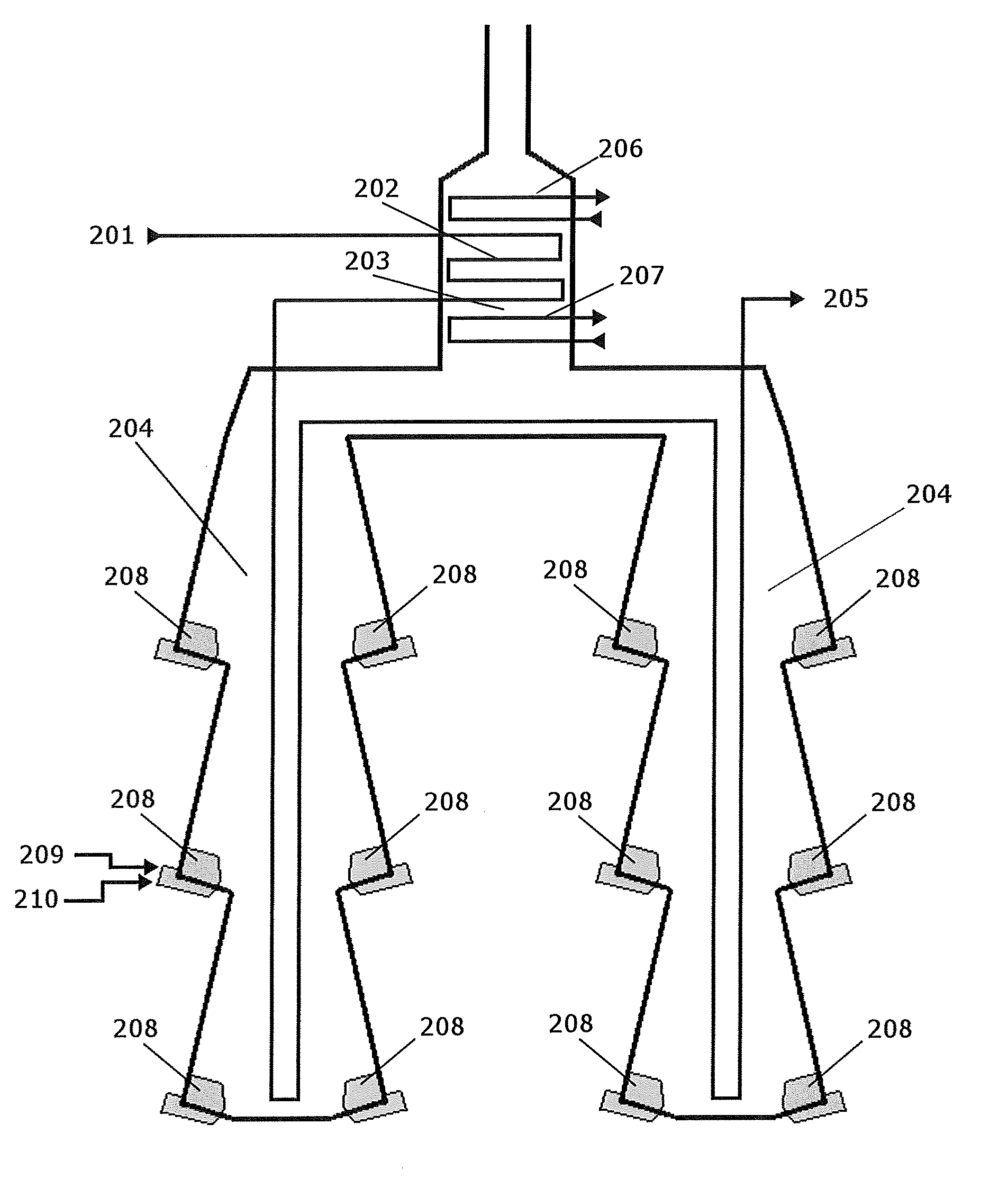
[0010] FIG. 2 is a schematic drawing of a cracking furnace.
[0011] FIG. 3 is a grey scale of the burner of FIG. 1 showing the calculated temperature distribution of the burner simulated using CFD analysis.
SUMMARY
[0012] The present disclosure provides a method to determine the need for one or more of heat conducting channels, fins, protuberances on the internal surface of a fluid fired burner, or internal baffles, the burner operating at temperatures of not less than 600.degree. C., comprising at least one metal component having a thickness T and a planar uninsulated surface directly facing (forming part of) the furnace and internal baffles within the burner modifying the flow of one or more oxidant and fuel and an internal having a grid of one or more heat conducting channels, fins, or protuberances, or internal baffles, forming part of the burner wherein one or more of oxidant and fuel flow over said one or more heat conducting channels, fins, protuberances on the internal surface of said metal and remove heat from the surface comprising forming a virtual or material model of said burner and determining using one or more methods comprising computational fluid dynamics, burner testing, pilot plant testing and commercial trials to determine if the burner operates at temperatures below its distortion temperature.
[0013] A further embodiment comprises a computational fluid dynamics method comprising simulation of a burner under equilibrium operating conditions of a furnace comprising:
[0014] a. calculating the heat flux [in W/m.sup.2 K] from the furnace through the surface of the metal component;
[0015] b. calculating the convective heat transfer from the internal surface of the metal component to said one or more of oxidant and fuel;
[0016] c determining an equilibrium temperature of the metal component at operating conditions of the furnace;
[0017] d. comparing the calculated equilibrium temperature of the metal component to the distortion temperature of the metal component;
[0018] e. if the distortion temperature of the metal component is less than 20.degree. C. below the calculated equilibrium temperature of the metal component modifying one or more of: [0019] i) modifying the heat conducting channels, fins, protuberances dimension and density on the internal surface of said metal component; and [0020] ii) the internal baffles
[0021] therefor modifying the velocity of gas and heat transfer coefficient on the internal surface of said metal component;
[0022] f) reiterating steps a) through e) until the calculated temperature of the metal component is at least 20.degree. C. lower than the distortion temperature of the metal component.
[0023] In a further embodiment once step f has been satisfied further modifying one or more of the heat conducting channels, fins, protuberances dimension and density, or size, location and number of the internal baffles, while meeting the criterion of step f) to minimize the manufacturing cost.
[0024] In a further embodiment further comprising modifying the flow rate of oxidant and fuel to determine a safe operating window for said burner.
[0025] In a further embodiment the fuel is natural gas.
[0026] In a further embodiment the oxidant is selected from air and mixtures of oxygen and an inert gas.
[0027] In a further embodiment the burner is a wall burner.
[0028] In a further embodiment the burner is a top downward directed burner.
[0029] In a further embodiment the burner is a floor burner.
[0030] In a further embodiment a burner for a chemical reactor is prepared as above.
[0031] In a further embodiment a burner for a boiler is prepared as above.
[0032] In a further embodiment a burner for a heater is prepared as above.
[0033] A further embodiment provides a chemical reformer having one or more burner as above.
[0034] A further embodiment provides a boiler having one or more burners as above.
[0035] A further embodiment provides a superheater having one or more burners as above.
[0036] A further embodiment provides a chemical cracker having one or more burners as above.
[0037] A further embodiment provides a chemical refiner having one or more burners as above.
[0038] In a further embodiment there is provided a method as above, comprising one or more of burner testing, pilot plant testing and commercial trials comprising:
[0039] a. manufacturing one or more burner components or the burner per se from a metal stable at temperatures 700.degree. C. to about 1350.degree. C. having for one or more of heat conducting channels, fins, protuberances of a selected dimension and density, and one or more internal baffles of a selected size and location;
[0040] b. testing the burner or burner components in one or more of burner testing, pilot plant testing and commercial trials at anticipated operating temperatures and various flow conditions of the fuel and oxidant over said one or more of heat conducting channels, fins, protuberances, and internal baffles to determine if the temperature of the burner or components under the test conditions is less than 20.degree. C. below the heat distortion temperature of the metal;
[0041] c. if the temperature of the burner or components under the test conditions is less than 20.degree. C. below the heat distortion temperature of the metal manufacturing a new more burner components or the burner having one or more modifications to dimensions of the heat the conducting channels, fins, protuberances and density the heat the conducting channels, fins, protuberances, size, location and number of internal baffles to improve the heat transfer properties thereof;
[0042] d. repeating steps a through c until the heat distortion temperature of the burner or components is more than 20.degree. C. below the heat distortion temperature of the metal.
DETAILED DESCRIPTION
[0043] Other than in the operating examples or where otherwise indicated, all numbers or expressions referring to quantities of ingredients, reaction conditions, etc. used in the specification and claims are to be understood as modified in all instances by the term "about." Accordingly, unless indicated to the contrary, the numerical parameters set forth in the following specification and attached claims are approximations that can vary depending upon the properties that the present disclosure desires to obtain. At the very least, and not as an attempt to limit the application of the doctrine of equivalents to the scope of the claims, each numerical parameter should at least be construed in light of the number of reported significant digits and by applying ordinary rounding techniques.
[0044] Notwithstanding that the numerical ranges and parameters setting forth the broad scope of the disclosure are approximations, the numerical values set forth in the specific examples are reported as precisely as possible. Any numerical values, however, inherently contain certain errors necessarily resulting from the standard deviation found in their respective testing measurements.
[0045] Also, it should be understood that any numerical range recited herein is intended to include all sub-ranges subsumed therein. For example, a range of "1 to 10" is intended to include all sub-ranges between and including the recited minimum value of 1 and the recited maximum value of 10; that is, having a minimum value equal to or greater than 1 and a maximum value of equal to or less than 10. Because the disclosed numerical ranges are continuous, they include every value between the minimum and maximum values. Unless expressly indicated otherwise, the various numerical ranges specified in this application are approximations.
[0046] All compositional ranges expressed herein are limited in total to and do not exceed 100 percent (volume percent or weight percent) in practice. Where multiple components can be present in a composition, the sum of the maximum amounts of each component can exceed 100 percent, with the understanding that, and as those skilled in the art readily understand, that the amounts of the components actually used will conform to the maximum of 100 percent.
[0047] As used in this specification, and as it relates to the burner material, substantially metal or substantially metallic, metal and metallic all mean, relative to the total construction of the burner not less than 80% of the burner is metallic and the balance is an optional ceramic over coating on limited external surfaces of the burner as described below. In other words, the burner has no more than 20 wt. % of ceramic or refractory, or no more than 10% or no more than 5%, of ceramic or refractory.
[0048] As used in this specification, cooling channels are machined into the internal surface of the burner, the dimensions of the cooling channels refers to the width and height of the cooling channels. The width of the cooling channels is determined at the base of the cooling channel. The height of the cooling channel (ribs) refers to the height of the wall of the cooling channel above the base of the channel. However, if walls of the cooling channel are not perpendicular to the metal component then it refers to the height from the outer tip of the wall to the base of the cooling channel.
[0049] As used in this specification, fins refer to thin ribbons of metal adhered to the inner surface of the burner, the dimensions of the cooling fins refers to the thickness and height of the cooling fins above the surface of the metal.
[0050] As used in this specification, protuberances refer to small discrete surface modification to increase surface area and turbulence at the surface.
[0051] As used in this specification, baffles refer to metal plates internal to the burner that are used to modify the flow path and velocity of one or more oxidant or fuel over surfaces exposed to high furnace temperatures.
[0052] The density of the cooling channels, fins, protuberances or combinations thereof means the number of channels fins or array of protuberances per unit length transverse to the channels fins or array of protuberances (e.g. 5 channels per cm.) in those areas where the channels are present. This is distinct from the surface area coverage of the cooling channels. For example if only half of the internal surface of the metal component has cooling channels fins or protuberances, the channels fins or protuberances would have a different dimension than for channels covering the entire surface of the metal component. The fabrication costs for these different designs would differ so that in some embodiments the channel, fin, protuberance or protuberance array design or combinations thereof and surface coverage (either total or segregated by the type of heat conductive structure) is optimized to reduce manufacturing cost.
[0053] There is a significant amount of prior relating to cooling of burner tips directly exposed to the furnace. In some embodiments, this art requires some sort of "swirling" vane to direct gas passing out of the nozzle across the surface of the nozzle. There does not appear to be any art relating to providing a metal component such as a planar piece or sheet exposed directly to the furnace, without insulation (e.g. a refractory) with cooling channels, fins, or protuberances, or combinations thereof on the surface not exposed to the furnace (e.g. the reverse or internal side).
[0054] As used herein planar refers to the degree of curvature of an element. But the current disclosure is not limited by the shape or geometry of the sides of the enclosure (e.g. box). While planar surfaces are exemplified, embodiments where the sides of the enclosure are curved or wavy are also envisioned.
[0055] In some embodiments the fuel is predominantly a fluid fuel, for example a gas such as natural gas. In some embodiments the fuel could be a liquid hydrocarbon for example a saturated C.sub.4-10 aliphatic or cyclic hydrocarbon. The fuel is not a solid particulate such as pulverized coal.
[0056] In some embodiments the oxidant comprises gaseous oxygen, for example air but it may also comprise mixtures of oxygen and inert gases such as nitrogen. The mixtures may comprise up to about 60 wt. % of inert gas, for example from 60 to 40 wt. % of inert gas.
[0057] The burners of the present disclosure comprise a chamber upstream from the exit to the furnace through which one or more of the oxidant and the fuel mix pass before entering the furnace. The chamber comprises one or more metal components having one or more faces or surfaces which are directly exposed to the furnace. The opposite side of the metal component faces the interior of the chamber. In accordance with the present disclosure the heat conducting channels, fins or protuberances or combinations thereof are provided on the inward facing side of the metal component through which one or more of the oxidant and fuel pass removing heat from the metal component.
[0058] However the issue is determining by calculation (e.g. CFD) or experiments (burner testing, pilot plant trials or plant trials) or combinations thereof the dimension and density of channels, fins, protuberances or combinations thereof to provide the appropriate amount of cooling so that the part does not distort or degrade (soften or melt) under the conditions of use. In some embodiments the temperature of the metal component should be kept at least 20.degree. C. below the distortion or softening temperature of the metal.
[0059] In one embodiment the first step in the present disclosure is to make a computer model of the burner in question and particularly the chamber and the metal component(s) which are to be directly exposed to the furnace without an insulation covering. The computer model may be generated by any known design software used in CAD/CAM applications. In preparing the model as a starting point the sides of the metal component directly exposed to the furnace should be free of channels. The opposite side (e.g. inside the chamber) may be free of heat conducting channels, fins, or protuberances or combinations thereof or have heat conducting channels, fins, protuberances or combinations thereof having a size, density and surface coverage based on an estimate of an experienced operator. The CAD/CAM model of the interior of the burner should be free of baffles.
[0060] In some embodiments a starting point for the modeling may include the following.
[0061] The longitudinal channels, if present, may have a height to width ratio from 0.1 to 2 in some embodiments from 0.5 to 2, in some embodiments from 0.5 to 1. The ribs may have a height from 4 to 25 mm, or from 8 to 22 mm, in some instances from 10 to 20 mm.
[0062] The fins may have dimensions and spacing comparable to the longitudinal channels. They may have a height form about 4 to 25 mm, or from 8 to 22 mm, in some instances form 10 to 20 mm and a thickness from 2 to 20 mm, in some embodiments from 5 to 1.5 cm and be spaced apart 2 mm to 2 cm, in some instances from 5 mm to 1.5 cm.
[0063] The fins may have a number of cross sectional shapes, such as rectangular, square, triangular or trapezoidal. A trapezoidal shape may not be entirely intentional, but may arise from the manufacturing process, for example when it is too difficult or costly to manufacture (e.g. cast or machine) a triangular cross section.
[0064] In some embodiments the fin may be cast as part of the metal surface or be welded to the metal surface.
[0065] The protuberances are closed solids.
The protuberance may have geometrical shape, having a relatively large external surface that contains a relatively small volume, such as for example tetrahedrons, pyramids, cubes, cones, a section through a sphere (e.g. hemispherical or less), a section through an ellipsoid, a section through a deformed ellipsoid (e.g. a tear drop) etc. Some useful shapes for a protuberance include:
[0066] a tetrahedron (pyramid with a triangular base and 3 faces that are equilateral triangles);
[0067] a Johnson square pyramid (pyramid with a square base and sides which are equilateral triangles);
[0068] a pyramid with 4 isosceles triangle sides;
[0069] a pyramid with isosceles triangle sides (e.g. if t is a four faced pyramid the base may not be a square it could be a rectangle or a parallelogram);
[0070] a section of a sphere (e.g. a hemi sphere or less);
[0071] a section of an ellipsoid (e.g. a section through the shape or volume formed when an ellipse is rotated through its major or minor axis);
[0072] a section of a tear drop (e.g. a section through the shape or volume formed when a non uniformly deformed ellipsoid is rotated along the axis of deformation); and
[0073] a section of a parabola (e.g. section though the shape or volume formed when a parabola is rotated about its major axis--a deformed hemi- (or less) sphere), such as e.g. different types of delta-wings.
[0074] The spacing and height of the protuberances is comparable to that for fins. They may have a height form about 4 to 25 mm, or from 8 to 22 mm, in some instances form 10 to 20 mm and a thickness from 2 to 20 mm, in some embodiments from 5 to 15 cm and be spaced apart 2 mm to 2 cm, in some instances from 5 mm to 1.5 cm.
[0075] The protuberances may also be cast on to the internal surface of the metal. In some embodiments the protuberances form an array. In some embodiments the array is symmetrical, for example they may be in parallel rows (linear array) or with the protuberances in adjacent rows offset by the array spacing (diamond type array)
[0076] The channels, fins, protuberances or combinations thereof may cover from about 15 to 100%, in some embodiments from 25 to 100%, in some embodiments from 60 to 100% of the internal surface area of the flow path. When the ribs or channels cover less than 100% of the internal surface area of the flow path the ribs or channels form a continuous series of parallel ribs or channels at least on the internal surface of the portions of the burner exposed to the cracking furnace.
[0077] In some of embodiments the burner may have baffles that span between 50 to 100% of the burner width and reduce the flow area adjacent to surfaces exposed to high furnace temperatures by 20 to 70%.
[0078] In some embodiments there is provided a burner wherein there is a descending baffle depending from a region not more than 10% forward of the forward lip of said one or more outlets for at least a gaseous oxidant, to the forward lip of said one or more outlets for said one or more gaseous oxidants, said baffle descending inside the upper metal section of the burner from 50 to 90% of the height of the front face of said burner; and extending laterally across the inner surface of the burner from 100 to 75% of the width of the face of said burner, said descending baffle being positioned so that there are substantially equal openings (as used herein substantially equal openings means a variation in height that is less than 10%, or for example less than 5%, or less than 2%) on each side of the descending baffle relative to the side walls of the metal upper section and where necessary said descending baffle having one or more circular channels there through to permit one or more fuel supply lines to pass there through.
[0079] In a further embodiment there is provided a burner further comprising an ascending baffle extending forward from the upper wall of said lower metal flow passage into from 45 to 85% of the open area in the chamber of a metal upper section.
[0080] In a further embodiment there is provided a burner wherein said ascending baffle extending forward from the upper wall of said lower metal flow passage is bent in its forward section up towards the open top to provide an upwards facing ascending baffle parallel to the inner front wall of upper section and where required the upward extending section of said ascending baffle having one or more circular channels there through to permit one or more fuel supply lines to pass there through.
[0081] In a further embodiment there is provided a burner wherein said ascending baffle extending forward from the upper wall of said lower metal flow passage further comprises on the surface facing the inner front wall of upper section a series of parallel longitudinal internal ribs to direct the flow of said at least a gaseous oxidant over the internal surface of said substantially metallic flow passage.
[0082] And in some embodiments both the ascending and descending baffles may be present.
[0083] The metallic walls may have a thickness from 4 to 25 mm, or from 8 to 22 mm, in some instances from 10 to 20 mm.
[0084] In some embodiments the burner design or components thereof may be fabricated in a size form test burner to commercial plant size and experimentally tested using burner test facilities, pilot plant facilities or in a plant trial. The resistance to heat distortion of the fabricated burner are evaluated and modification may be made to the burner to improve the resistance to distortion. The testing of the modified burner would be an iterative process to achieve a suitable design.
[0085] In some embodiments the model of the metal component is then used in a computational fluid dynamic model of the burner in operation. Input data includes the flow rate and composition of the oxidant and fuel, the furnace geometry, and the process duty. There is a balance between the convective cooling of the fuel and oxidant flowing through the burner relative to the heat release of the combusting fuel. The convective cooling flow rate is interdependent with the heat release rate, fuel composition and typical excess air, which results in a wet molar concentration of oxygen between 1% and 10%. The required heat release of the burner and the flow rate of oxidant and fuel will define the range of sizes of the burner. This range will be further defined by the range of velocities of oxidant and fuel velocities required for cooling. And the maximum practical pressure drop of the fuel and oxidant as it flows through the burner. The flow rate of fuel and oxidant can be calculated as needed by a person of ordinary skill in the art.
[0086] The output of the simulation includes the conductive, convective and radiative heat transfer throughout the furnace and burner. In some embodiments the heat of combustion of the fuel is considered as the flow rate will increase the convective heat transfer to the fluid flowing over the channels but it will also increase the heat and temperature in the furnace. The model should calculate the equilibrium temperature of the furnace and the equilibrium temperature of the metal part. The model will then compare the equilibrium temperature of the metal part to a predetermined temperature such as a specified temperature differential (e.g. 10.degree. C., to 40.degree. C.) below the softening temperature or heat distortion temperature. Potentially the melting temperature could be used but it is too close to failure of the part. There is no safety margin.
[0087] If the model determines the equilibrium temperature is the required differential below the softening temperature then the model need not be run further. If the temperature is too close to the heat distortion temperature the dimensions, density, and surface coverage of the channels as well as the internal baffles are modified and the equilibrium temperature is compared to the required temperature (e.g. the distortion temperature -20.degree. C.). The process is reiterated for each change in the channels dimensions, density and surface coverage until a satisfactory equilibrium temperatures is obtained (e.g. the distortion temperature -20.degree. C.).
[0088] In some embodiments after the appropriate equilibrium temperature is obtained the metal surface may be further modeled to obtain a more economic pattern for the channels and/or a more mechanically stable pattern for the channels.
[0089] The chamber may be of any shape. In some embodiments the chamber has at least one planar face exposed to the furnace. The chamber maybe selected from one or more of the following shapes: an N sided prism where N is a whole number greater that 4 (e.g. 5, 6, 7, 8) although in some instances N is an even number greater than 4. (hexagonal prism, octagonal prism etc.) The chamber may comprise a combination of shapes a rectangular prism (N is 4) or a triangular prism N is 3. Spheres and tubes are generally not preferred shapes for the chamber. The chamber typically has an inlet on one side (planar face) and an outlet on an opposite was or a top.
[0090] In some embodiments, it is desirable to have a turbulent flow through the chamber. In some instances there may be one or more internal baffles within the chamber to increase turbulence of the flow. The turbulent flow also helps with heat transfer from the channels to the fluid flowing through the chamber.
[0091] The metallic components directly exposed to the furnace used in the burner should be mechanically stable at temperatures from about from about 700.degree. C. to about 1350.degree. C., or from about 850.degree. C. to about 1200.degree. C., or from 850.degree. C. to 1100.degree. C. The metal components may be made from any high temperature steel such as stainless steel selected from wrought stainless, austenitic stainless steel and HP, HT, HU, HW and HX stainless steel, heat resistant steel, and nickel based alloys. The coil pass may be a high strength low alloy steel (HSLA); high strength structural steel or ultra high strength steel. The classification and composition of such steels are known to those skilled in the art.
[0092] In one embodiment the stainless steel, for example heat resistant stainless steel, comprises from 13 to 50, or 20 to 50, or from 20 to 38 weight % of chromium. The stainless steel may further comprise from 20 to 50, or from 25 to 50, or from 25 to 48, or from about 30 to 45 weight % of Ni. The balance of the stainless steel may be substantially iron.
[0093] The disclosed embodiments may also be used with nickel and/or cobalt based extreme austentic high temperature alloys (HTAs). In some embodiments the alloys comprise a major amount of nickel or cobalt. In some embodiments the high temperature nickel based alloys comprise from about 50 to 70, or from about 55 to 65 weight % of Ni; from about 20 to 10 weight % of Cr; from about 20 to 10 weight % of Co; and from about 5 to 9 weight % of Fe and the balance one or more of the trace elements noted below to bring the composition up to 100 weight %. In some embodiments the high temperature cobalt based alloys comprise from 40 to 65 weight % of Co; from 15 to 20 weight % of Cr; from 20 to 13 weight % of Ni; less than 4 weight % of Fe and the balance one or more trace elements as set out below and up to 20 weight % of W. The sum of the components adding up to 100 weight %.
[0094] In some embodiments the steel may further comprise a number of trace elements including at least 0.2 weight %, up to 3 weight %, or for example 1.0 weight %, up to 2.5 weight %, or not more than 2 weight % of manganese; from 0.3 to 2, or for example 0.8 to 1.6, or for example less than 1.9 weight % of Si; less than 3, or less than 2 weight % of titanium, niobium (for example less than 2.0, or less than 1.5 weight % of niobium) and all other trace metals; and carbon in an amount of less than 2.0 weight %. The trace elements are present in amounts so that the composition of the steel totals 100 weight %
[0095] The burners as described above may be mounted in the wall of the furnace, could be floor mounted or ceiling mounted (e.g. as in a reformer). The refractory lining in the wall, floor or ceiling, as the case may be, has an opening through which the burner fits and then a refractory and cement are used to close the opening through which the burner was fitted. The burner is also attached to the external supports (frame) for the furnace and the external ducts to supply oxidant, for example air, to the burner. Also the fuel supply lines are connected to the fuel supply, for example, natural gas.
[0096] The metallic burners also comprise ancillary equipment such as pilot lights, and the fuel feed there for joining members for duct works and any mechanical oxidant flow controllers as well as instrumentation.
[0097] The present disclosure is illustrated by the following demonstration.
Demonstration
[0098] One embodiment of the present disclosure will now be demonstrated with reference to FIGS. 1, 2 and 3. FIG. 2 shows a simple schematic of Foster-Wheeler pyrolysis furnace such as used for cracking ethane to ethylene. In a cracker such as the ethylene cracker shown in FIG. 2, the feed stock 201 (a mixture of ethane and steam) enters a coil 202 passing through the exhaust portion of the 203 typically referred to as the convection section of the furnace. The feed is pre-heated in the convection section to a controlled and specific temperature. In some embodiments, steam is also heated in the convection section in a separate coil 207. In some embodiments, boiler feed water is also heated in the convection section in a separate coil 206. The coil 202 with the feed stock 201 passes through the radiant section 204 of the furnace before it exits 205 at which point it may be rapidly quenched to a lower temperature. The coil 202 passes through the radiant section of the furnace 204 it is exposed to the heat generated by the burners 208. The furnace shown in FIG. 2 displays a cracking furnace configuration with two radiant sections with the coil passing through both radiant sections. There are numerous other configurations including a furnace with a single radiant section.
[0099] Computational fluid dynamics (CFD) has been used previously to model the operation of the radiant section of a NOVA Chemicals ethane cracker. In some embodiments the operation of this section of this particular pyrolysis furnace has pre-heated combustion air at 215.degree. C. air and fuel composed of a mixture of 60% molar fraction hydrogen and 40% molar fraction natural gas at a pre-heated temperature of 130.degree. C. The burners within the furnace are commercially available low-NOX burners constructed of refractory typically used in high temperature furnaces. The single burner heat release rate is approximately 5 MMBtu/hr (1.5 MW) with the flue gas wet oxygen molar concentration at 2%. Real plant data and CFD model results have been compared including but not limited to the surface temperature of the process coils, surface temperature of the refractory burners, flue gas exit temperature and process coil heat transfer rates. A comparison of the modeled vs. plant operating measurements was found to be sufficiently close (within 10%) such that it could be used for the prediction of plant performance in a practical manner.
[0100] This validation work was used to define model requirements and settings by the inventors to predict the performance of a burner designed using metal as a material of construction instead of refractory material in accordance with the present disclosure. FIG. 2 shows a profile view of a Foster-Wheeler style pyrolysis furnace with the radiant section 204 and the locations of burners 208. FIG. 3 shows the surface temperature as predicted by CFD of a burner (such as shown in FIG. 1) designed in accordance with this patent and operating at conditions equal to described in the paragraph above. The temperature scale has a range selected to show temperatures between 500.degree. C. and 1000.degree. C. Temperatures below or above this range are shown at the extremes of the scale. FIG. 3 shows that for this example burner the surface temperature is no higher than 900.degree. C. which is below the distortion temperature of metals that would be used for burner construction. This shows that there is a balance of heat transfer between the firing rate of the burner and the internal cooling rate induced by the combustion air and the design of the metal burner.
* * * * *
D00000
D00001
D00002
D00003
XML
uspto.report is an independent third-party trademark research tool that is not affiliated, endorsed, or sponsored by the United States Patent and Trademark Office (USPTO) or any other governmental organization. The information provided by uspto.report is based on publicly available data at the time of writing and is intended for informational purposes only.
While we strive to provide accurate and up-to-date information, we do not guarantee the accuracy, completeness, reliability, or suitability of the information displayed on this site. The use of this site is at your own risk. Any reliance you place on such information is therefore strictly at your own risk.
All official trademark data, including owner information, should be verified by visiting the official USPTO website at www.uspto.gov. This site is not intended to replace professional legal advice and should not be used as a substitute for consulting with a legal professional who is knowledgeable about trademark law.