Electric Submersible Pump Dual Gas And Sand Separator
TODD; Jared Michael ; et al.
U.S. patent application number 16/462913 was filed with the patent office on 2019-10-10 for electric submersible pump dual gas and sand separator. The applicant listed for this patent is Halliburton Energy Services, Inc.. Invention is credited to Michael A. MURRAY, Wesley John NOWITZKI, Randy S. ROBERTS, David Linn SELF, Jared Michael TODD.
| Application Number | 20190309768 16/462913 |
| Document ID | / |
| Family ID | 62839686 |
| Filed Date | 2019-10-10 |

| United States Patent Application | 20190309768 |
| Kind Code | A1 |
| TODD; Jared Michael ; et al. | October 10, 2019 |
ELECTRIC SUBMERSIBLE PUMP DUAL GAS AND SAND SEPARATOR
Abstract
An electric submersible pump (ESP) dual gas and sand separator is described. An ESP system includes a dual gas and sand separator having a fluid flow pathway including an upward turn and a downward turn, the upward turn separating solids from a fluid flowing through the pathway and the downward turn separating gas from the fluid, the dual separator including a sand sump below the fluid flow pathway. The separator includes tubing that extends below the ESP assembly, at least a portion of the tubing including two concentric pipes. A dual gas and sand separating method includes causing pumped fluid to turn from upwards to downwards and then upwards again in a tortious pathway below the ESP assembly before the fluid travels into a centrifugal pump intake, and collecting solids that separate out of the multiphase fluid in a solid sump coupled below the tortious pathway.
| Inventors: | TODD; Jared Michael; (Edmond, OK) ; MURRAY; Michael A.; (Claremore, OK) ; MURRAY; Michael A.; (Claremore, OK) ; NOWITZKI; Wesley John; (Tulsa, OK) ; ROBERTS; Randy S.; (Tulsa, OK) ; SELF; David Linn; (Laurel, MS) | ||||||||||
| Applicant: |
|
||||||||||
|---|---|---|---|---|---|---|---|---|---|---|---|
| Family ID: | 62839686 | ||||||||||
| Appl. No.: | 16/462913 | ||||||||||
| Filed: | January 11, 2018 | ||||||||||
| PCT Filed: | January 11, 2018 | ||||||||||
| PCT NO: | PCT/US2018/013269 | ||||||||||
| 371 Date: | May 21, 2019 |
Related U.S. Patent Documents
| Application Number | Filing Date | Patent Number | ||
|---|---|---|---|---|
| 62444927 | Jan 11, 2017 | |||
| Current U.S. Class: | 1/1 |
| Current CPC Class: | F04D 29/426 20130101; F04D 13/10 20130101; E21B 43/38 20130101; F04D 29/708 20130101; E21B 43/128 20130101 |
| International Class: | F04D 29/70 20060101 F04D029/70; F04D 13/10 20060101 F04D013/10; F04D 29/42 20060101 F04D029/42; E21B 43/38 20060101 E21B043/38 |
Claims
1. An electric submersible pump (ESP) assembly comprising: a tubular shroud separating a housing of the ESP assembly from a well casing, the tubular shroud extending between a base of a centrifugal pump and a location below the ESP assembly, the tubular shroud sealed from well fluid ingress at the centrifugal pump base; a stinger hanging below the tubular shroud, the stinger comprising: an annular jacket, the annular jacket comprising a plurality of inlet openings and coupled to a sand sump below the annular jacket, a pipe inwards of the annular jacket, the pipe open at a top end and a bottom end of the pipe, a space above the inlet openings and between an inner diameter of the annular jacket and an outer diameter of the pipe sealed from upward fluid flow, and an inside of the pipe fluidly coupled to an inner diameter of the tubular shroud.
2. The ESP assembly of claim 1, wherein the tubular shroud and stinger define a production fluid pathway that extends through the plurality of inlet openings in the stinger, continues downward between the inner diameter of the annular jacket and the outer diameter of the pipe, turns at the bottom end of the pipe and flows upward through the inside of the pipe, continues upward through the inner diameter of the tubular shroud, enters the pump intake and then continues into the centrifugal pump.
3. The ESP assembly of claim 2, wherein the ESP assembly comprises an induction motor encased in a motor housing, wherein the production fluid flows between an outside of the motor housing and the inner diameter of the tubular shroud as the production fluid continues upward through the inner diameter of the tubular shroud on the way to the pump intake.
4. The ESP assembly of claim 2, wherein gas separates out of the production fluid when the production fluid continues downward between the inner diameter of the annular jacket and the outer diameter of the pipe.
5. The ESP assembly of claim 4, wherein the gas exits the stinger and enters a casing annulus through a top row of the plurality of inlet openings.
6. The ESP assembly of claim 2, wherein sand separates out of the production fluid when the production fluid turns at the bottom end of the pipe, and the sand collects in the sand sump.
7. The ESP assembly of claim 1, wherein the bottom end of the pipe is chamfered.
8. The ESP assembly of claim 1, wherein the plurality of openings comprise two offset rows of slots.
9. An electric submersible pump (ESP) system comprising: a dual gas and sand separator, the dual gas and sand separator hanging below a downhole ESP assembly from a shroud; the shroud surrounding an inlet section of a centrifugal pump of the ESP assembly; the dual gas and sand separator comprising a stinger, the stinger comprising a plurality of concentric pipes and a sand sump hanging below an outer pipe of the plurality of concentric pipes.
10. The ESP system of claim 9, wherein the outer pipe of the plurality of concentric pipes comprises at least one inlet opening extending through a wall of the outer pipe.
11. The ESP system of claim 10, wherein the at least one inlet opening comprises two rows of offset slots.
12. The ESP system of claim 10, wherein the dual gas and sand separator is configured such that fluid flows through the at least one opening and downwards towards the sand sump, turns at the bottom of an inner pipe of plurality of concentric pipes and flows upward through the inside of the inner pipe.
13. The ESP system of claim 12, further comprising multiphase fluid flowing through the dual gas and sand separator, and wherein gas separates from the multiphase fluid as it flows downward towards the sand sump and sand separates from the multiphase fluid as the fluid turns upwards at the bottom of the inner pipe.
14. The ESP system of claim 13, wherein the sand collects in the sand sump.
15. The ESP system of claim 9, wherein an inside of an inner pipe of the plurality of concentric pipes is fluidly coupled to an inlet of a centrifugal pump in a downstream direction from the inside of the inner pipe towards the inlet of the centrifugal pump.
16. An electric submersible pump (ESP) system comprising a dual gas and sand separator suspended below an ESP assembly, the dual gas and sand separator having portions defining a fluid flow pathway comprising a 180.degree. upward turn and a 180.degree. downward turn, the 180.degree. upward turn configured to separate solids from a fluid flowing through the pathway and the 180.degree. downward turn configured to separate gas from the fluid flowing through the pathway, the dual gas and sand separator comprising a solid collection sump below the portions defining the fluid flow pathway.
17. The ESP system of claim 16, wherein the dual gas and sand separator comprises an inner tube fluidly coupled to an intake of a centrifugal pump of the ESP assembly.
18. The ESP system of claim 16, wherein the solid collection sump extends between twenty and five hundred feet in length.
19. The ESP system of claim 16, wherein the dual gas and sand separator comprises a shroud, a stinger secured below the shroud and the solid collection sump secured below the stinger.
20. An electric submersible pump (ESP) dual gas and sand separation method comprises: pumping a multiphase fluid downhole in a well to bring the multiphase fluid to a well surface; causing the fluid to make a turn from upwards to downwards and a subsequent turn from downwards to upwards in a tortious pathway below the ESP assembly before the multiphase fluid travels into a centrifugal pump intake; and collecting solids that separate out of the multiphase fluid in a collection receptacle below the tortious pathway.
21. The ESP dual gas and sand separating method of claim 20, wherein the turn from upwards to downwards separates gas from the multiphase fluid, and wherein the subsequent turn from downwards to upwards separates the solids from the multiphase fluid.
Description
BACKGROUND
1. Field of the Invention
[0001] Embodiments of the invention described herein pertain to the field of submersible pump assemblies. More particularly, but not by way of limitation, one or more embodiments of the invention enable an electric submersible pump dual gas and sand separator.
2. Description of the Related Art
[0002] When pressure within a well, such as an oil or water well, is not enough to force fluid out of the well, submersible pump assemblies are used to artificially lift fluid to the surface. A typical vertical electric submersible pump (ESP) assembly consists of, from bottom to top, an electrical motor, seal section, pump intake and centrifugal pump, which are all connected together with shafts. Centrifugal pumps accelerate a working fluid through stages of rotating impellers, which are keyed to the rotatable pump shaft. The electrical motor supplies torque to the shafts, which provides power to turn the centrifugal pump. The electrical motor is generally connected to a power source located at the surface of the well using a motor lead cable. The entire assembly is placed into the well inside a casing. The casing separates the submersible pump assembly from the well formation. Perforations in the casing allow well fluid to enter the casing. These perforations are generally below the motor and are advantageous for cooling the motor if it can be arranged that fluid is drawn passed the outside of the motor as it makes it way from the perforations up to the pump intake.
[0003] Many underground formations also contain well-born solids, such as consolidated and unconsolidated sand. Induced hydraulic fracturing or hydrofracking, commonly known as fracking, may also cause solids such as proppant to be deposited into well bore formations in the form of "frac" material. Whether the solids are naturally present or consist of frac material, the hydrocarbon laden fluid must pass through those solids on its way to the pump intake, and ultimately to the surface. While the pump is in operation, the hydrocarbon fluid can carry the solids through the pump components. Such well-born solids may have severe abrasive effects on the submersible pump components and increase the wear during use. Abrasive wear to the pump causes inefficiency in its operation, such as by undesirably eroding tight clearances. In addition, sand can also plug pump pathways and openings, such as intake filters, which can lead to pump starvation, overheating and failure.
[0004] Care must be taken to avoid the damage caused by solids in the produced well fluid. In the case of an ESP, a failure of the pump or any support components in the pump assembly can be catastrophic as it means a delay in well production and having to remove the pump from the well for repairs. A submersible pump system capable of removing abrasive solids from produced fluids would be an advantage in all types of submersible assemblies.
[0005] Another challenge to economic and efficient ESP operation is pumping gas laden fluid. For example, formations with oil often also contain natural gas. When pumping gas laden fluid, the gas may separate from the denser fluid due to the pressure differential created when the pump is in operation. If there is a sufficiently high gas volume fraction, typically about 10% or more, the pump may experience a decrease in efficiency and decrease in capacity or head (slipping). If gas continues to accumulate on the suction side of the impeller it may entirely block the passage of other fluid through the centrifugal pump. When this occurs the pump is said to be "gas locked" since proper operation of the pump is impeded by the accumulation of gas. As a result, careful attention to gas management in submersible pump systems is needed in order to improve the production of gas laden fluid from subsurface formations.
[0006] Currently in wells with gas laden fluid, attempts are made to remove gas either using shrouds or gas separators. Shrouds redirect the flow of well fluid to induce gas to break away from the liquid before the fluid enters the inlet to the pump. Gas separators, on the other hand, sometimes serve as the pump intake in gassy wells. Gas separators attempt to separate gas and liquid by spinning the fluid before it continues to the pump. In wells with high solid content, slotted screens are employed around the pump intake ports in an attempt to remove the solids before they enter the pump. These screens frequently become clogged or include slots that are too large to remove smaller solid particles.
[0007] A problem that arises in wells having high concentrations of both gas and solids is that, in addition to the aforementioned problems, the solids reduce the effectiveness of the gas handling equipment. For example, in assemblies employing an inverted shroud for gas separation, the shroud can fill with sand, plugging the inlet to the pump. Further, current equipment designed to separate gas from well fluid is distinct from equipment employed to separate solids. Incorporating two pieces of specialized equipment for both gas and solid removal into an ESP assembly adds to the cost and complexity of the pump assembly.
[0008] It would be an advantage for submersible pump assemblies operating in both gaseous and solid-laden environments to have dual gas and solid separation capability. Therefore, there is a need for an improved electric submersible pump dual gas and sand separator.
SUMMARY
[0009] Embodiments described herein generally relate to an electric submersible pump (ESP) dual gas and sand separator. An ESP dual gas and sand separator is described.
[0010] An illustrative embodiment of an ESP assembly includes a tubular shroud separating a housing of the ESP assembly from a well casing, the tubular shroud extending between a base of a centrifugal pump and a location below the ESP assembly, the tubular shroud sealed from well fluid ingress at the centrifugal pump base, a stinger hanging below the tubular shroud, the stinger including an annular jacket, the annular jacket including a plurality of inlet openings and coupled to a sand sump below the annular jacket, a pipe inwards of the annular jacket, the pipe open at a top end and a bottom end of the pipe, a space above the inlet openings and between an inner diameter of the annular jacket and an outer diameter of the pipe sealed from upward fluid flow, and an inside of the pipe fluidly coupled to an inner diameter of the tubular shroud. In some embodiments, the tubular shroud and stinger define a production fluid pathway that extends through the plurality of inlet openings in the stinger, continues downward between the inner diameter of the annular jacket and the outer diameter of the pipe, turns at the bottom end of the pipe and flows upward through the inside of the pipe, continues upward through the inner diameter of the tubular shroud, enters the pump intake and then continues into the centrifugal pump. In certain embodiments, the ESP assembly includes an induction motor encased in a motor housing, wherein the production fluid flows between an outside of the motor housing and the inner diameter of the tubular shroud as the production fluid continues upward through the inner diameter of the tubular shroud on the way to the pump intake. In some embodiments, gas separates out of the production fluid when the production fluid continues downward between the inner diameter of the annular jacket and the outer diameter of the pipe. In certain embodiments, the gas exits the stinger and enters a casing annulus through a top row of the plurality of inlet openings. In some embodiments, sand separates out of the production fluid when the production fluid turns at the bottom end of the pipe, and the sand collects in the sand sump. In certain embodiments, the bottom end of the pipe is chamfered. In some embodiments, the plurality of openings include two offset rows of slots.
[0011] An illustrative embodiment of an electric submersible pump (ESP) system includes a dual gas and sand separator, the dual gas and sand separator hanging below a downhole ESP assembly from a shroud, the shroud surrounding an inlet section of a centrifugal pump of the ESP assembly, the dual gas and sand separator including a stinger, the stinger including a plurality of concentric pipes and a sand sump hanging below an outer pipe of the plurality of concentric pipes. In some embodiments, the outer pipe of the plurality of concentric pipes includes at least one inlet opening extending through a wall of the outer pipe. In certain embodiments, the at least one inlet opening includes two rows of offset slots. In some embodiments, the dual gas and sand separator is configured such that fluid flows through the at least one opening and downwards towards the sand sump, turns at the bottom of an inner pipe of plurality of concentric pipes and flows upward through the inside of the inner pipe. In certain embodiments, the ESP system further includes multiphase fluid flowing through the dual gas and sand separator, and wherein gas separates from the multiphase fluid as it flows downward towards the sand sump and sand separates from the multiphase fluid as the fluid turns upwards at the bottom of the inner pipe. In some embodiments, the sand collects in the sand sump. In certain embodiments, an inside of an inner pipe of the plurality of concentric pipes is fluidly coupled to an inlet of a centrifugal pump in a downstream direction from the inside of the inner pipe towards the inlet of the centrifugal pump.
[0012] An illustrative embodiment of an electric submersible pump (ESP) system includes a dual gas and sand separator suspended below an ESP assembly, the dual gas and sand separator having portions defining a fluid flow pathway including a 180.degree. upward turn and a 180.degree. downward turn, the 180.degree. upward turn configured to separate solids from a fluid flowing through the pathway and the 180.degree. downward turn configured to separate gas from the fluid flowing through the pathway, the dual gas and sand separator including a solid collection sump below the portions defining the fluid flow pathway. In some embodiments, the dual gas and sand separator includes an inner tube fluidly coupled to an intake of a centrifugal pump of the ESP assembly. In certain embodiments, the solid collection sump extends between twenty and five hundred feet in length. In some embodiments, the dual gas and sand separator includes a shroud, a stinger secured below the shroud and the solid collection sump secured below the stinger.
[0013] An illustrative embodiment of an electric submersible pump (ESP) dual gas and sand separation method includes pumping a multiphase fluid downhole in a well to bring the multiphase fluid to a well surface, causing the fluid to make a turn from upwards to downwards and a subsequent turn from downwards to upwards in a tortious pathway below the ESP assembly before the multiphase fluid travels into a centrifugal pump intake, and collecting solids that separate out of the multiphase fluid in a collection receptacle below the tortious pathway. In some embodiments, the first turn from upwards to downwards separates gas from the multiphase fluid, and the subsequent turn from downwards to upwards separates the solids from the multiphase fluid.
[0014] In further embodiments, features from specific embodiments may be combined with features from other embodiments. For example, features from one embodiment may be combined with features from any of the other embodiments. In further embodiments, additional features may be added to the specific embodiments described herein.
BRIEF DESCRIPTION OF THE DRAWINGS
[0015] Advantages of the present invention may become apparent to those skilled in the art with the benefit of the following detailed description and upon reference to the accompanying drawings in which:
[0016] FIG. 1 is a perspective view of an exemplary submersible pump assembly with a dual gas and sand separator of illustrative embodiments and illustrating an exemplary flow path of lifted fluid.
[0017] FIG. 2 is a perspective view of a stinger and sand sump of an illustrative embodiment.
[0018] FIG. 3A is a perspective view of a stinger of an illustrative embodiment.
[0019] FIG. 3B is cross sectional view across line 3B-3B of FIG. 3A of a stinger of an illustrative embodiment.
[0020] FIG. 3C is an enlarged view of a stinger top of an illustrative embodiment of the stinger of FIG. 3B.
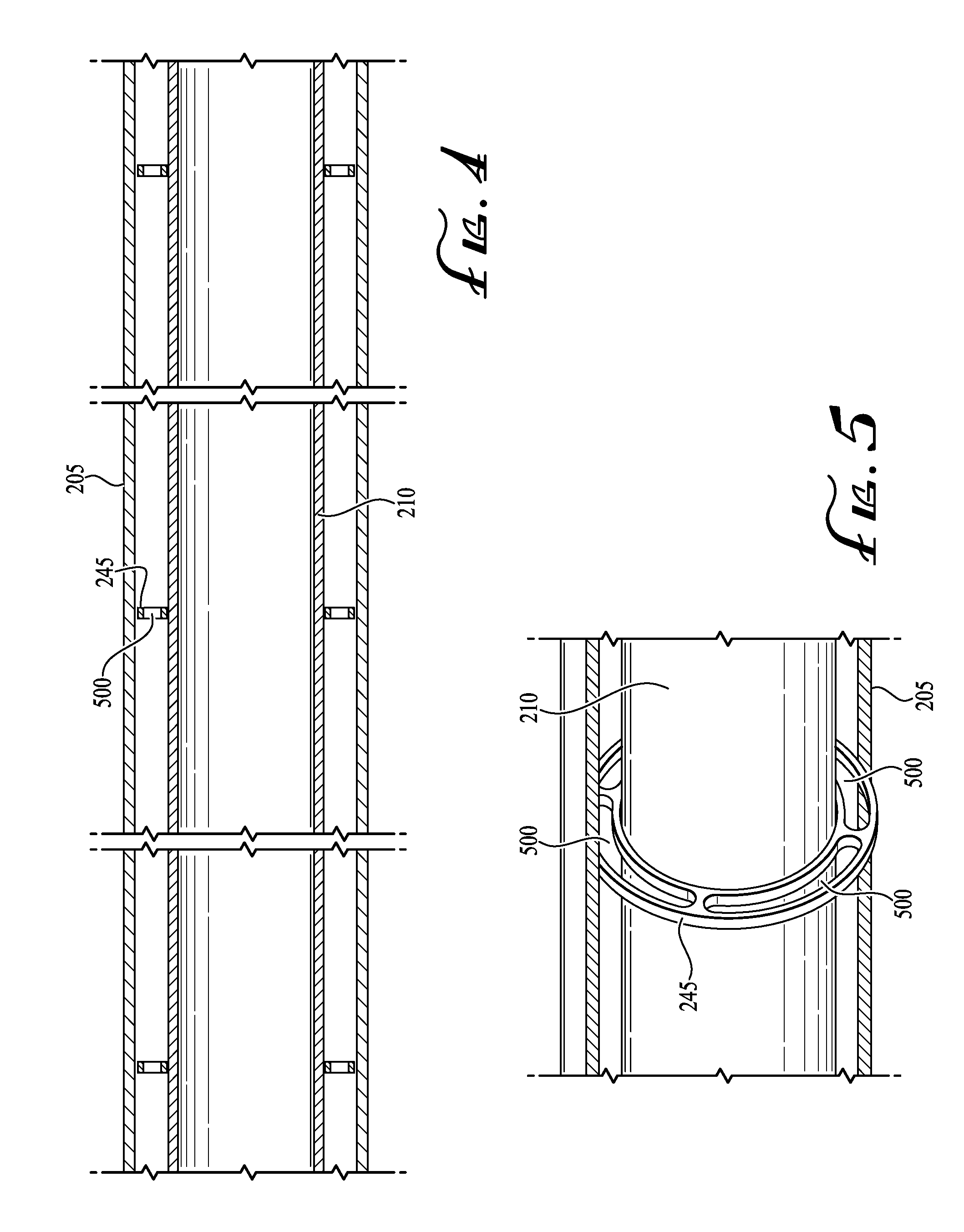
[0021] FIG. 4 is an enlarged view of the bearing supports of FIG. 3B of a dual gas and sand separator of an illustrative embodiment.
[0022] FIG. 5 is a perspective view of a bearing support of a dual gas and sand separator of an illustrative embodiment.
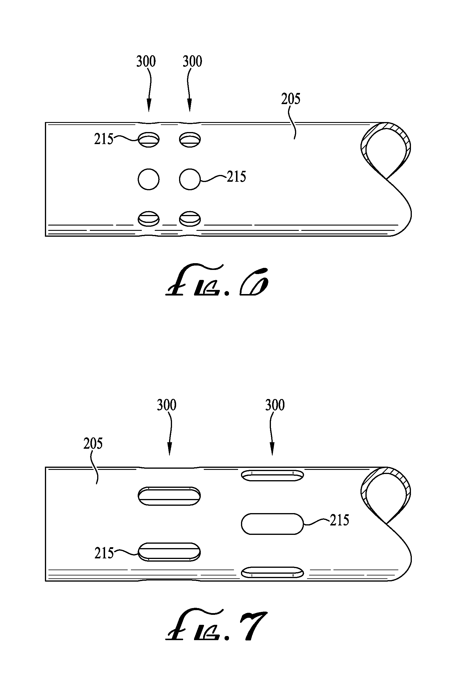
[0023] FIG. 6 is a perspective view of a system inlet of an illustrative embodiment having exemplary round inlet openings.
[0024] FIG. 7 is a perspective view of a system inlet of an illustrative embodiment having exemplary offset rows of slots of an illustrative embodiment.
[0025] While the invention is susceptible to various modifications and alternative forms, specific embodiments thereof are shown by way of example in the drawings and may herein be described in detail. The drawings may not be to scale. It should be understood, however, that the embodiments described herein and shown in the drawings are not intended to limit the invention to the particular form disclosed, but on the contrary, the intention is to cover all modifications, equivalents and alternatives falling within the scope of the present invention as defined by the appended claims.
DETAILED DESCRIPTION
[0026] An electric submersible pump (ESP) dual gas and sand separator will now be described. In the following exemplary description, numerous specific details are set forth in order to provide a more thorough understanding of embodiments of the invention. It will be apparent, however, to an artisan of ordinary skill that the present invention may be practiced without incorporating all aspects of the specific details described herein. In other instances, specific features, quantities, or measurements well known to those of ordinary skill in the art have not been described in detail so as not to obscure the invention. Readers should note that although examples of the invention are set forth herein, the claims, and the full scope of any equivalents, are what define the metes and bounds of the invention.
[0027] As used in this specification and the appended claims, the singular forms "a", "an" and "the" include plural referents unless the context clearly dictates otherwise. Thus, for example, reference to a "pipe" includes one or more pipes.
[0028] "Coupled" refers to either a direct connection or an indirect connection (e.g., at least one intervening connection) between one or more objects or components. The phrase "directly attached" means a direct connection between objects or components.
[0029] As used in this specification and the appended claims, "downstream" with respect to a downhole ESP assembly refers to the longitudinal direction towards the wellhead. As used herein, the "top" of a component refers to the downstream-most side of the component.
[0030] As used in this specification and the appended claims, "upstream" refers to the longitudinal direction deeper into the well and/or away from the wellhead. As used herein, the "bottom" of a component refers to the upstream-most side of the component.
[0031] As used in this specification and the appended claims, the terms "solid," "solids," "debris" and "sand" refer interchangeably to sand, rocks, rock particles, dirt, soils, slurries, proppant and any other non-liquid, non-gaseous matter found in the fluid being pumped by an artificial lift pumping system.
[0032] As used in this specification and the appended claims, the term "sand sump" refers to a pit, hollow, receptacle and/or low lying place that serves as a repository for sand separated from fluid being drawn into the ESP pump of illustrative embodiments.
[0033] So as not to obscure the invention, illustrative embodiments are primarily described herein in terms of a downhole ESP assembly. However, the invention is not so limited and may be equally employed in other types of pumps, artificial lift and/or fluid moving applications where it is desirable to separate both gas and solid from liquid prior to the multiphase fluid's entry into the pump and/or fluid mover.
[0034] Illustrative embodiments of the invention described herein provide a dual gas and sand separator for an ESP downhole assembly. Illustrative embodiments may separate at least a portion of both gas and sand from well fluid prior to the fluid's entry into the ESP's centrifugal pump. Illustrative embodiments may store sand in a manner that may prevent the sand from plugging the intake of the ESP pump and/or may avoid flushing of separated sand back into the casing annulus. By reducing sand and gas entering the pump, illustrative embodiments may reduce the likelihood of gas locking, reduce abrasive damage to the pump and/or reduce clogging of pump filters and openings. Illustrative embodiments may be simple and inexpensive to implement since illustrative embodiments may be employed in a single separator component, and the constituent parts such as piping may be readily available to ESP providers and may be premanufactured.
[0035] Illustrative embodiments may include a closed shroud around an ESP assembly inside the well casing. The shroud may be secured to the ESP assembly at the pump base and sealed from the ingress of well fluid at the shroud's upper attachment point to the pump. The shroud may extend from the pump base to below the ESP assembly, below the ESP motor and downhole sensors. A stinger of illustrative embodiments may be attached below the shroud. The stinger may include two concentric pipes. The inner pipe may have a chamfered upstream (bottom) end and an inside that is fluidly coupled to the inside of the shroud and the inlet to the ESP's centrifugal pump. The outer pipe (jacket) may have a wall with openings proximate the top for fluid entry and/or gas exit, and include a bottom portion and/or be coupled to a sand sump. The space between the outer diameter of the inner pipe and the inner diameter of the jacket may be sealed to block fluid flow between the stinger and the shroud in the space.
[0036] During operation of the ESP assembly of illustrative embodiments, fluid may enter casing perforations and travel into the system inlet openings in the stinger jacket. Once the fluid enters the openings in the jacket, it may fall downwards inside the jacket, a portion of gas breaking out of the fluid at the turn downwards. The break out gas may exit the stinger through the openings in the stinger jacket and enter the casing annulus. The lifted fluid may continue to travel downwards between the inner pipe and jacket, until it reaches the bottom of the inner pipe and/or a hole in the inner pipe. At the bottom of the inner pipe, the fluid may turn from flowing downwards to flowing upwards, and flow upwards inside the inner pipe. At the turn from downwards to upwards, solids may separate out of the fluid and fall downwards into the sand sump coupled below the jacket. After turning upwards, the well fluid may then travel upwards into the inside of the inner pipe, then pass into the inside of the shroud between the outer diameter of the ESP housing and the inner diameter of the shroud, until it reaches the pump intake. The fluid may then enter the pump intake and continue into the pump with both a lower gas and a lower solid content than fluid entering the casing. As the fluid passes the motor, it may cool the motor.
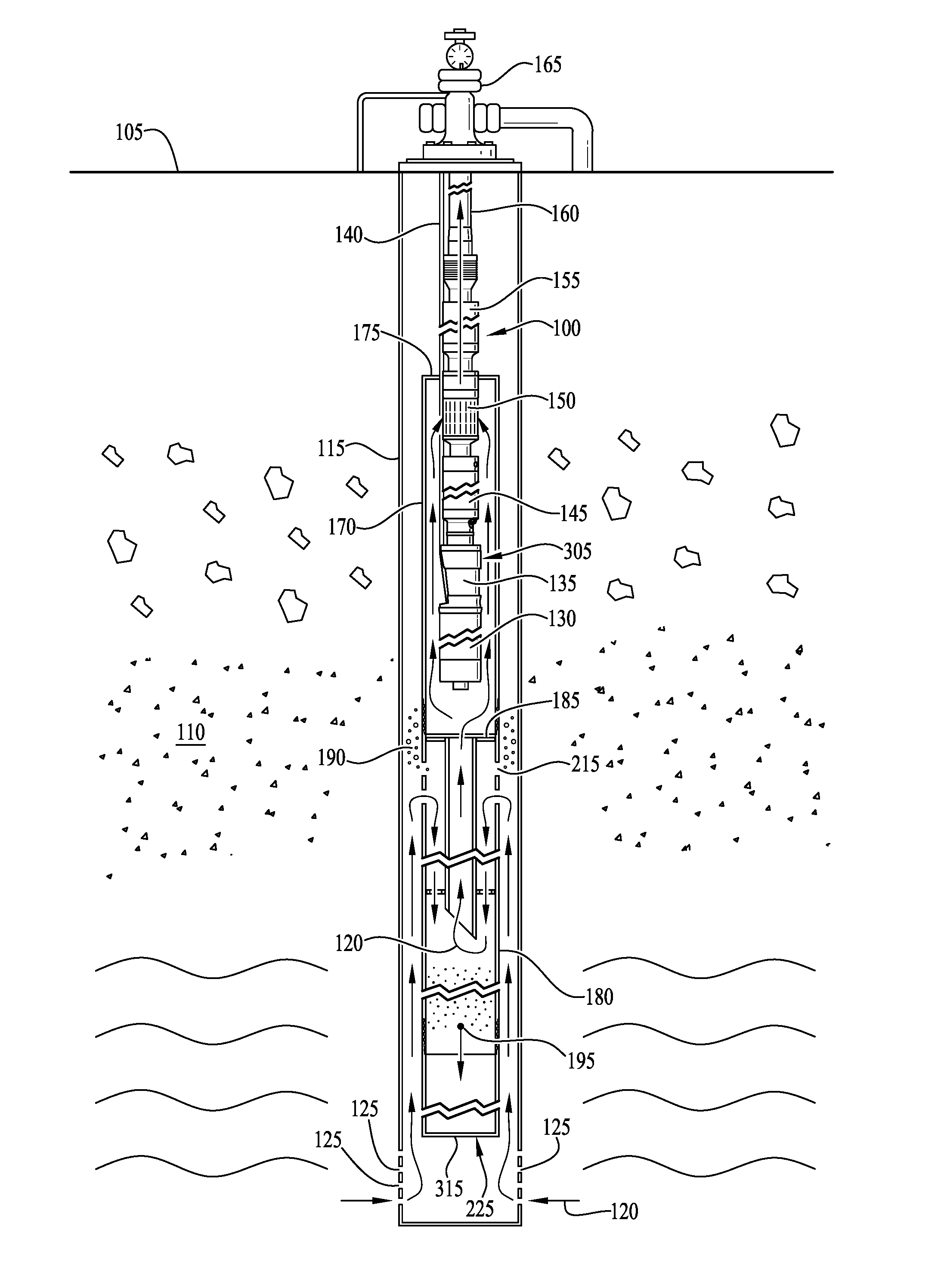
[0037] FIG. 1 is an illustrative embodiment of an electric submersible pump (ESP) assembly with dual gas and sand separator of an illustrative embodiment. ESP assembly 100 may be located downhole in a well below surface 105. The well may, for example, be several hundred or a few thousand feet deep. ESP assembly 100 may be vertical or may be slightly curved, bent and/or angled, depending on well direction, although it is currently preferred that the ESP assembly be arranged generally in a vertical direction to maximize the separation benefits of illustrative embodiments. The well may be an oil well, water well, and/or well containing other hydrocarbons, such as natural gas, and/or another production fluid. ESP assembly 100 may be separated from underground formation 110 by well casing 115. In an exemplary embodiment, casing 115 may be six, seven or nine inches in diameter, or another similar diameter. Production fluid (lifted fluid) 120 may enter well casing 115 through casing perforations 125. Casing perforations 125 may be either above or below ESP assembly 100 and/or ESP intake 150. In the embodiment shown in FIG. 1, casing perforations 125 are below ESP assembly 100 and below ESP intake 150.
[0038] ESP assembly 100 may include downhole sensors 130 which may detect, measure and/or provide information regarding motor revolution rate, discharge pressure, vibration in one, two, or three axes, intake pressure, discharge pressure, gauge temperature, and/or other operating conditions to a user interface, variable speed drive controller and/or data collection computer and/or programmable logic controller (PLC) on surface 105. Pump flow rate may be inferred from differential pressures when a discharge pressure transducer is included. ESP motor 135 may be an induction motor, such as a two-pole, three phase squirrel cage induction motor. Components of ESP assembly 100 may be encased in ESP housing 305, which housing 305 may define the outer diameter of one or more components of ESP assembly 100. Power cable 140 may provide power to ESP motor 135 and/or carry data from downhole sensors 130 to surface 105. Downstream of motor 135 may be motor protector (seal section) 145, ESP intake 150, multi-stage centrifugal ESP pump 155 and production tubing 160. Motor protector 145 may serve to equalize pressure and keep the motor oil separate from well fluid 120. ESP intake 150 may include intake ports and/or a slotted screen, and serve as the intake for production fluid 120 into centrifugal ESP pump 155. ESP pump 155 may be a multi-stage centrifugal pump including stacked impeller and diffuser stages. Other components of ESP assemblies may also be included in ESP assembly 100, such as a tandem charge pump (not shown) located between centrifugal ESP pump 155 and intake 150. Shafts of motor 135, motor protector 145, ESP intake 150 and ESP pump 155 may be connected together (i.e., splined) and be rotated by shaft of motor 135. Production tubing 160 may carry production fluid 120 from the discharge of ESP pump 155 towards wellhead 165.
[0039] ESP assembly 100 may include shroud 170. Shroud top 175 may be sealed around ESP assembly 100 above ESP intake 150, such as at the base of ESP pump 155 or on production tubing 160, such that production fluid 120 may not enter ESP pump 155 except from the inside of shroud 170. Shroud top 175 may be attached by a split clamp secured around the base of ESP pump 155, ESP pump 155 and/or production tubing 160. The clamp may seal shroud top 175 from well fluid ingress and provide a sealed opening through which power cable 140 may extend so as to reach motor 135 below. Shroud 170 may extend from shroud top 175 to below downhole sensors 130, below motor 135 and/or below the lowermost (upstream most) component of ESP assembly 100. In some embodiments, shroud 170 may extend at least about five feet below the bottom-most component of ESP assembly 100, depending on the depth of the well, extending below ESP motor 135 and/or below downhole sensors 130.
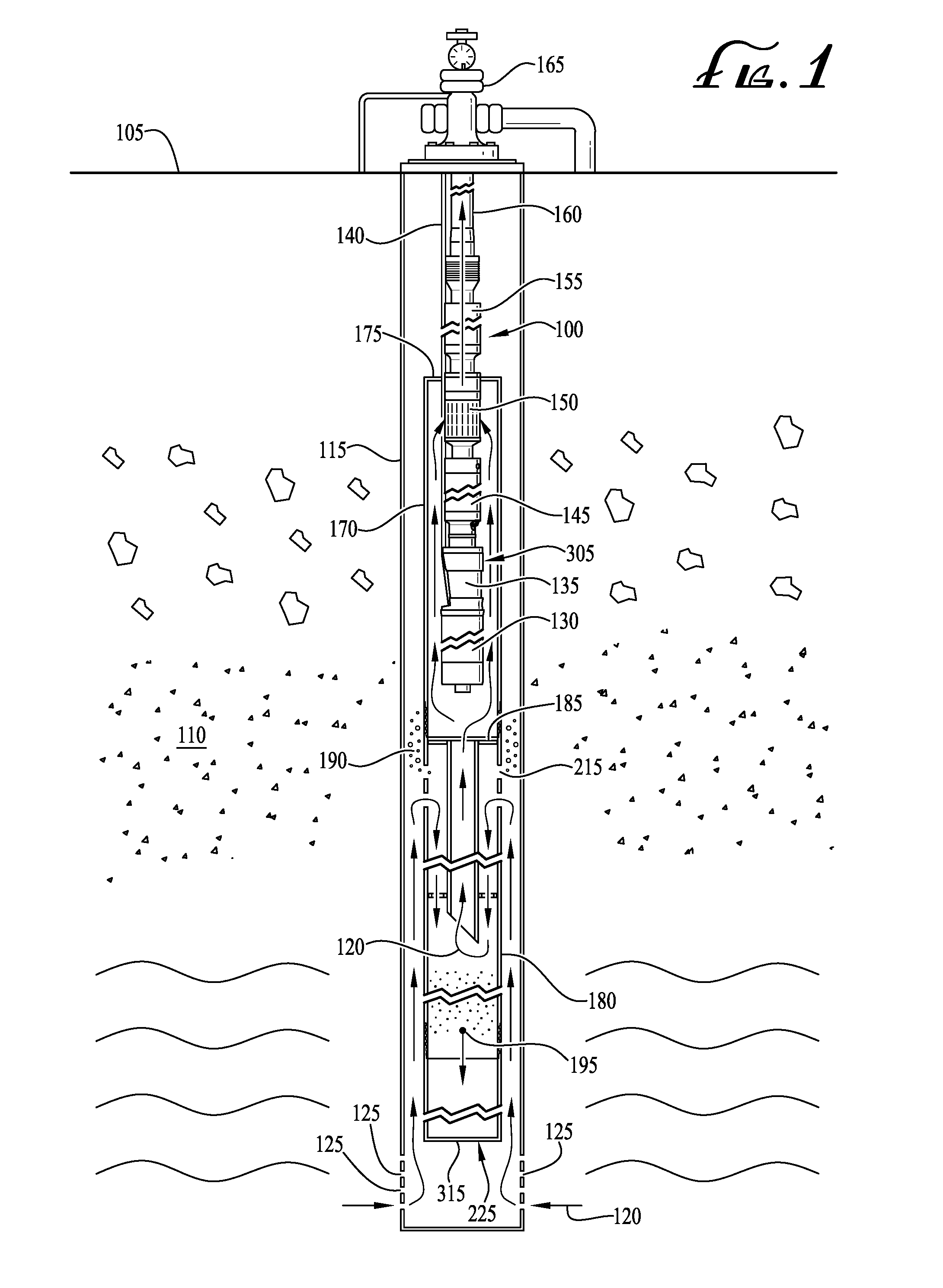
[0040] Stinger 180 may be attached to shroud bottom 185 of shroud 170. A stinger of illustrative embodiments is illustrated in FIG. 2. Stinger 180 may be secured to shroud bottom 185 by top threads 200, screws, bolts or another attachment means known to those of skill in the art of ESPs. Stinger 180 may extend about twenty to forty feet below shroud bottom 185, depending on the depth of the well in which ESP assembly 100 is placed. Stinger 180 may include two and/or at least two concentric pipes and/or tubes: outer pipe (jacket) 205 and inner pipe 210. Outer pipe 205 may have a larger diameter than inner pipe 210 and surround inner pipe 210 with a space between them. Outer pipe 205 and inner pipe 210 may both be hollow to create pathways for fluid flow both inside and outside the pipes 205, 210.
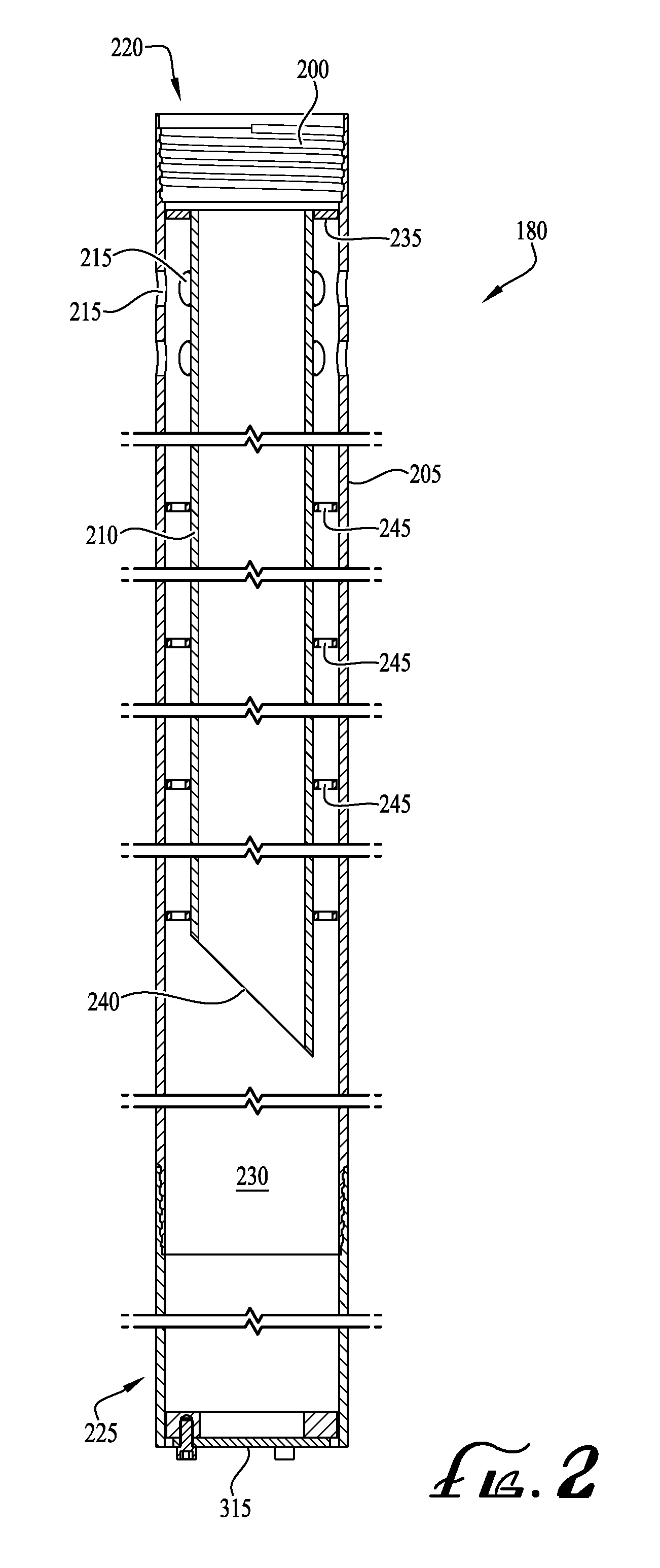
[0041] Turning to FIG. 3C, FIG. 6 and FIG. 7, the top portion of outer pipe 205 may be a system inlet and/or system inlet portion, section and/or piece and include inlet openings 215. Inlet openings 215 may be proximate stinger top 220, such as within 3.0 inches, 5.0 inches, 6.0 inches, 1.0 foot or another similar distance from stinger top 220, and may be slots, circular openings, square openings, oval openings or another shape of opening. FIG. 6 illustrates exemplary round inlet openings 215, and FIG. 7 illustrates exemplary slotted inlet openings 215. Inlet openings 215 may be arranged in one, two or more rows 300. Where there are multiple rows 300 of openings 215, openings 215 in adjacent rows 300 may be offset from one another as illustrated in FIG. 7. In an illustrative embodiment, there may be six slot-shaped openings 215 per row 300, with slots in adjacent rows 300 evenly spaced apart and rotated 30.degree., for example. Inlet openings 215 may assist gas separation, such as separation of natural gas from oil or other fluid hydrocarbons. Where two or more rows 300 of openings 215 are employed, a lower row of slots 215 may allow for fluid entry, and an upper row of offset openings 215 may allow for separated gas to exit jacket 205 rather than build up on the inside of the inlet piece (the top portion 220 of outer pipe 205). In some embodiments, where inlet openings 215 are non-circular in shape, for example slots, the slots may be slanted and/or tilted from longitudinal.
[0042] In some embodiments, sand sump 225 may be attached below, coupled to and/or may form a closed bottom of stinger 180. Referring to FIG. 2 and FIG. 3A, sand sump 225 may be a blind piece threaded on stinger bottom threads 310 and/or attached to the bottom of stinger 180. Sand sump 225 may be closed on a bottom end and may form solid collection receptacle 230 for sand and/or other solids falling from inside stinger 180. The bottom end of sand sump 225 may include and/or be formed by cap 315 to prevent sand from falling back into the casing annulus. In certain embodiments, sand sump 225 may be a length of tube and/or pipe threaded, bolted and/or attached to the bottom of stinger 180. Sand sump 225 may be a collection receptacle, repository and/or reservoir between twenty and five-hundred feet long that may collect sand that falls out of lifted production fluid 120 and keep the sand from moving into the casing annulus.
[0043] The space at stinger top 220 above inlet openings 215 and between inner pipe 210 and outer pipe 205, may be sealed from well fluid 120. Plate 235 may be welded on and/or between the inner diameter of jacket 205 and the outer diameter of inner pipe 210 to form the seal to well fluid. Plate 235 may be disc shaped with a central opening so as to surround inner pipe 210 and securely block the area between inner pipe 210 and outer pipe 205 at and/or proximate the connection between shroud 170 and stinger 180 and/or between inner pipe 210 and outer pipe 205 above inlet openings 215. Plate 235 may prevent production fluid 120 located between inner pipe 210 and outer pipe 205 from moving upwards inside of shroud 170, and instead force this production fluid 120 to flow downwards between inner pipe 210 and outer pipe 205 before turning upwards inside of inner pipe 210.
[0044] Inner pipe 210 may be smaller in diameter and shorter in length than outer pipe 205, for example inner pipe 210 may be about two inches shorter, five inches shorter, ten inches shorter than outer pipe 205, or another similar length difference. Inner pipe 210 may hang below and/or be welded and/or attached to plate 235 on an upper end and/or side of inner pipe 210, and may have open bottom end 240 and/or may have a hole for fluid entry on a bottom portion and/or lower side. Inner pipe 210 bottom end 240 may be chamfered, slanted, stepped and/or angled, such as at a 30.degree., 45.degree. or 60.degree. angle, or another similar angle. Chamfered bottom end 240 may create a void and keep bottom end 240 unblocked from debris as the debris accumulates in solid collection receptacle 230 and/or sand sump 225. Supports 245 may be distributed and/or spaced along the length of outer pipe 205, between inner pipe 210 and outer pipe 215. Referring to FIG. 3B, FIG. 4 and FIG. 5, supports 245 may be bearings with apertures 500 that allow production fluid 120 to flow through supports 245 without impeding flow rate. Supports 245 may, for example, be spaced every 10 feet or every 15 feet, as needed to provide support for the long, thin stinger 180.
[0045] Pipes for shroud 170, stinger 180 and/or sand sump 225 may be sections of twenty-foot-long pipe and/or tubing that is threaded, bolted and/or otherwise attached together to achieve the desired length. Sections of pipe having other lengths may also be employed depending on the supplies that are readily available to those in the ESP industry.
[0046] Shroud 170 and stinger 180 may form a fluid flow pathway for production fluid 120 that induces both gas and solid to separate out of lifted fluid 120 as lifted fluid 120 enters casing 115 and travels from perforations 125 to ESP intake 150. Returning to FIG. 1, lifted fluid 120, which may contain gas (such as natural gas) and solid (such as sand, rock, dirt and/or other debris), may enter casing perforations 125. If, as shown in FIG. 1, perforations 125 are below ESP assembly 100, lifted fluid 120 may enter perforations 125 and travel upwards between well casing 115 and the outer diameter of sand sump 225 and/or the outer diameter of outer pipe (jacket) 205 towards system inlet openings 215. When lifted fluid 120 reaches inlet openings 215 in jacket 205, lifted fluid 120 may enter system inlet openings 215 and turn from flowing upwards to flowing downwards. Making a 180.degree. turn or about a 180.degree. turn, lifted fluid 120 may travel downwards between the inner diameter of jacket 205 and the outer diameter of inner pipe 210. As lifted fluid 120 makes its turn from flowing upwards to downwards, gas bubbles 190 may break out of lifted fluid 120. Where two or more rows 300 of system inlet openings 215 are employed, denser (gas poor) lifted fluid 120 may primarily enter the lower or lowest row, while less dense, gas rich fluid may primarily exit from the uppermost row of openings 215. Lifted fluid 120 may flow downward until it reaches bottom end 240 of inner pipe 210. At bottom end 240, lifted fluid 120 may turn 180.degree. from flowing downwards to flowing upwards inside inner pipe 210. As lifted fluid 120 makes its turn from downwards to upwards, sand and/or solids 195 may fall out of lifted fluid 120 and drop into solid collection receptacle 230 and/or sand sump 225, which may catch and confine solids 195. Production fluid 120 may then continue up along the inside of inner pipe 210, flow into the inside of shroud 170, along the outside of motor housing 305 to cool ESP motor 130. Lifted fluid 120 may continue to flow between the housing 305 of ESP assembly 100 and the inner diameter of shroud 170 to ESP intake 150. At ESP intake 150, lifted fluid 120 may enter ESP pump 155 and be carried through production tubing 160 to surface 105.
[0047] Using the system of illustrative embodiments, production fluid 120 entering ESP pump 155 and/or flowing through production tubing 160 may have lower gas and lower solid content than fluid entering casing perforations 125, as a result of the tortuous pathway provided by stinger 180 and shroud 170. As lifted fluid 120 turns, gravity may assist heavier phases to travel downward, while lighter phases travel upward, serving to separate the solid, liquid and gas. In this manner, higher concentrations of desirable liquid such as oil or other liquid hydrocarbons may travel through pump 155 to the exclusion of undesirable gas and solid, decreasing the risk of gas locking, plugging or abrasive damage from gas and solid.
[0048] If perforations 125 are above ESP intake 150, lifted fluid 120 may enter casing perforations 125 and travel downwards between well casing 115 and shroud 170 until lifted fluid 120 reaches system inlet openings 215 in stinger 180. As production fluid 120 travels downwards from casing perforations 125 to inlet openings 215, gas 190 may separate out of lifted fluid 120, and then continue through the flow pathway inside stinger 180 as described above. Lifted fluid may pass housing 305 of motor before entering pump intake 150, which may keep motor 135 cool.
[0049] Shroud 170 may be steel or another strong, non-corrosive material and capable of supporting several hundred feet of shroud 170, stinger 180 and sand sump 225. Supports 245 may be bearings including apertures 500 large enough so as not to impede flow rate of production fluid 120.
[0050] An electric submersible pump (ESP) dual gas and sand separator has been described. Further modifications and alternative embodiments of various aspects of the invention may be apparent to those skilled in the art in view of this description. Accordingly, this description is to be construed as illustrative only and is for the purpose of teaching those skilled in the art the general manner of carrying out the invention. It is to be understood that the forms of the invention shown and described herein are to be taken as the presently preferred embodiments. Elements and materials may be substituted for those illustrated and described herein, parts and processes may be reversed, and certain features of the invention may be utilized independently, all as would be apparent to one skilled in the art after having the benefit of this description of the invention. Changes may be made in the elements described herein without departing from the scope and range of equivalents as described in the following claims. In addition, it is to be understood that features described herein independently may, in certain embodiments, be combined.
* * * * *
D00000
D00001
D00002
D00003
D00004
D00005
D00006
XML
uspto.report is an independent third-party trademark research tool that is not affiliated, endorsed, or sponsored by the United States Patent and Trademark Office (USPTO) or any other governmental organization. The information provided by uspto.report is based on publicly available data at the time of writing and is intended for informational purposes only.
While we strive to provide accurate and up-to-date information, we do not guarantee the accuracy, completeness, reliability, or suitability of the information displayed on this site. The use of this site is at your own risk. Any reliance you place on such information is therefore strictly at your own risk.
All official trademark data, including owner information, should be verified by visiting the official USPTO website at www.uspto.gov. This site is not intended to replace professional legal advice and should not be used as a substitute for consulting with a legal professional who is knowledgeable about trademark law.