Cam Follower Assembly
Ali Khan; Maqsood Rizwan ; et al.
U.S. patent application number 15/945052 was filed with the patent office on 2019-10-10 for cam follower assembly. The applicant listed for this patent is GM GLOBAL TECHNOLOGY OPERATIONS LLC. Invention is credited to Maqsood Rizwan Ali Khan, Kenneth J. Veenstra.
| Application Number | 20190309658 15/945052 |
| Document ID | / |
| Family ID | 67991937 |
| Filed Date | 2019-10-10 |


| United States Patent Application | 20190309658 |
| Kind Code | A1 |
| Ali Khan; Maqsood Rizwan ; et al. | October 10, 2019 |
CAM FOLLOWER ASSEMBLY
Abstract
An improved cam follower includes a lifter body, a spring seat, a tower, a spring and an anti-rotation member defining at least one interference rib. The lifter body may engage with a cam via a rolling member. The lifter body defines a longitudinal axis, a first open end, and a second end. The spring seat which defines a spring seat opening may be disposed at the first open end of the lifter body. The tower which includes an upper flange may be couples a pushrod to the lifter body. The spring may be disposed between the spring seat and the upper flange of the tower. The anti-rotation member may be disposed proximate to the first open end of the lifter body and includes an outer surface and an inner surface with an interference rib integral to the inner surface which engages with an upper region of the lifter body.
| Inventors: | Ali Khan; Maqsood Rizwan; (Rochester Hills, MI) ; Veenstra; Kenneth J.; (Jenison, MI) | ||||||||||
| Applicant: |
|
||||||||||
|---|---|---|---|---|---|---|---|---|---|---|---|
| Family ID: | 67991937 | ||||||||||
| Appl. No.: | 15/945052 | ||||||||||
| Filed: | April 4, 2018 |
| Current U.S. Class: | 1/1 |
| Current CPC Class: | F01L 1/14 20130101; F01L 1/2422 20130101; F01L 2305/00 20200501; F01L 1/146 20130101; F01L 2307/00 20200501; F01L 2001/467 20130101; F01L 2301/00 20200501; F01L 2305/02 20200501; F01L 13/0005 20130101 |
| International Class: | F01L 1/14 20060101 F01L001/14 |
Claims
1. An improved cam follower for a vehicle engine comprising: a lifter body operatively configured to engage with a cam via a rolling member, the lifter body defining a longitudinal axis, a lifter body diameter, a first open end, and a second end; a spring seat disposed at the first open end of the lifter body, the spring seat defining a spring seat opening; a tower operatively configured to couple a pushrod to the lifter body, the tower being disposed in a pin housing through the spring seat opening at the first open end of the lifter body, the tower having an upper flange; a spring disposed between the spring seat and the upper flange of the tower; and an anti-rotation member disposed proximate to the first open end of the lifter body, the anti-rotation member having an outer surface and an inner surface with an interference rib integral to the inner surface which engages with an upper region of the lifter body.
2. The improved cam follower as defined in claim 1 wherein the interference rib is substantially parallel to the longitudinal axis of the lifter body.
3. The improved cam follower as defined in claim 1 wherein the interference rib is substantially perpendicular to the longitudinal axis of the lifter body.
4. The improved cam follower as defined in claim 2 wherein the rolling member is affixed to the lifter body at the second end.
5. The improved cam follower as defined in claim 3 wherein the rolling member is affixed to the lifter body at the second end.
6. The improved cam follower as defined in claim 4 wherein a planar surface is defined on the interior surface of the anti-rotation member proximate to a lower end of the anti-rotation member.
7. The improved cam follower as defined in claim 5 wherein a planar surface is defined on the interior surface of the anti-rotation member proximate to a lower end of the anti-rotation member.
8. The improved cam follower as defined in claim 6 wherein the interference rib is over-molded onto the planar surface.
9. The improved cam follower as defined in claim 7 wherein the interference rib is over-molded onto planar surface.
10. The improved cam follower as defined in claim 6 wherein the lifter body defines a compatible planar surface being configured to engage with the planar surface of the anti-rotation member.
11. The improved cam follower as defined in claim 7 wherein the lifter body defines a compatible planar surface being configured to engage with the planar surface of the anti-rotation member.
12. The improved cam follower as defined in claim 10 wherein the interference rib deforms upon actuation of lifter body and roller onto the cam during an initial operation of the vehicle engine.
13. The improved cam follower as defined in claim 11 wherein the interference rib deforms upon actuation of lifter body and roller onto the cam during an initial operation of the vehicle engine.
14. An anti-rotation member for guiding a cam follower in a vehicle engine, the anti-rotation member comprising: an outer surface; an inner surface; and an interference rib integral to the inner surface, the interference rib being configured to deform and retain a first open end of a lifter body when the first open end of the lifter body engages with the interference rib.
15. The anti-rotation member as defined in claim 14 wherein the interference rib is over-molded onto the inner surface.
16. The anti-rotation member as defined in claim 14 wherein the interference rib is injection molded simultaneously with the inner surface and the outer surface.
Description
TECHNICAL FIELD
[0001] The present disclosure relates to cam followers and more particularly directed to a cam follower assembly for maintaining the position of lifter body relative to a camshaft.
BACKGROUND
[0002] Hydraulic valve lifters and solid valve lifters, for use in internal combustion engines, are well known in the engine art. A valve lifter of this type, engaging a camshaft lobe at one end and a push-rod or valve stern at the other end, slides reciprocally in a bore of the engine block. The lifter, typically assembled from the top side of the engine block, engages a camshaft lobe via a camshaft follower end which preferably includes a roller. Unless suitably constrained by an anti-rotation guide, a roller follower lifter may rotate radially in its bore during reciprocation, thereby undesirably misaligning its roller follower from the associated cam lobe.
[0003] Lifter anti-rotation guides in the prior art are positioned on and secured to the top side surface of the engine block adjacent the lifter bore. When fastened to the engine block above the lifter, a closely-fitting aperture in the anti-rotation guide snuggly surrounds an end of the lifter exposed above the engine block opposite the roller follower end. Within the anti-rotation guide aperture, a flat ("plastic shear") is generally defined on the inner surface of the guide aperture which mates with a similar feature on the lifter body of lifter to hold the lifter inside of the anti-rotation guide during the assembly process and to also prevent the lifter from rotating about its longitudinal axis during reciprocation engine operation. Typically, a lifter is installed into the anti-rotation guide as a sub-assembly, and then this subassembly is then installed onto the top side of the engine.
[0004] During the assembly and engine operation processes, the lifter must be positioned properly within the anti-rotation guide so that the roller of the lifter is properly aligned with the cam once this subassembly is attached to the engine. In the event the roller of the lifter is misaligned relative to the cam, it is understood that undesirable, premature degradation at the roller-cam interface may occur. As noted above, plastic guide shears are generally defined within the anti-rotation guide aperture in the form of a flat surface on the inner wall of the anti-rotation guide. However, such guide shears do not always maintain the lifter in position and when a lifter inadvertently falls out of the traditional anti-rotation guide, the risk of improperly orienting the lifter is heightened when the lifter is re-inserted into the guide later in the assembly process.
[0005] Accordingly, there is a need to improve the anti-rotation guides for lifters so that a lifter is maintained within the anti-rotation guide throughout the assembly process and properly aligned with the cam associated with the lifter when the lifter and anti-rotation guide is installed on an engine.
SUMMARY
[0006] The present disclosure provides an improved cam follower for a vehicle engine which maintains the position of the lifter within the guide throughout the assembly process so that the lifter guide's roller is properly aligned with the cam thereby reducing the risk of cam spalling or premature failure at the interface between the cam and the roller.
[0007] In one embodiment, the improved cam follower includes a lifter body, a spring seat, a tower, a spring and an anti-rotation member having one or more interference ribs. The anti-rotation of member of the present disclosure includes an upper end and a lower end, and may further include an outer surface and an inner surface with one or more interference ribs integral to the inner surface. The one or more interference ribs may be defined on an inner surface of the anti-rotation member proximate to the lower end. The interference rib is configured to abut the lifter body when the lifter body is inserted inside of the anti-rotation member. It is also understood that the interference rib(s) may deform upon insertion of the lifter body within the anti-rotation member, or the interference rib(s) may deform when the engine is operating and the lifter body reciprocates relative to the camshaft. In yet another embodiment, the interference rib(s) may simply disintegrate such that at least a portion of the interference rib falls off when the lifter body is inserted or when the engine is operating and the lifter body reciprocates relative to the camshaft. Under this circumstance, a small amount of the interference rib may go into the engine oil without disrupting the engine's operation.
[0008] The interference rib(s) or dimple may protrude from the inner surface of the anti-rotation member by a depth which falls in the range of 1 mm to 5 mm wherein the interference rib may be integral to the anti-rotation member via an injection molding process, or in yet another non-limiting, optional arrangement, the interference rib is integral to the anti-rotation member via an over-molding process. It is also understood that each interference rib may have a width which may fall in a range of about 1 mm to 5 mm. It is understood that the interference rib or dimple may come in various shapes. Regardless, the interference rib or dimple may be any raised feature which may deform or disintegrate as described.
[0009] While each anti-rotation member may include as few as one interference rib, an anti-rotation member of the present disclosure may, but not necessarily include a plurality of interference ribs in various regions of the inner surface. The inner surface of the anti-rotation member may vary such that the inner surface includes at least one flat region and at least one curved region 39. Regardless, the interference rib of the present disclosure may be integral to either a flat region or a curved region 39 of the inner surface.
[0010] The lifter body may be disposed along the longitudinal axis wherein the lifter body includes a first open end, and a second end. The lifter body may engage with a cam via a rolling member affixed to the second end. A spring seat may be disposed at the first open end of the lifter body wherein the spring seat defines a spring seat opening which supports the tower. An example, non-limiting tower may be implemented to couple a pushrod to the lifter body. The tower may also include an upper flange such that a spring may be disposed between the spring seat and the upper flange of the tower. As shown in FIGS. 2C-2D, the tower may, but not necessarily, be disposed in a pin housing through the spring seat opening at the first open end of the lifter body. The pin housing is disposed within the lifter body such that the pin housing, the tower, the lifter body and the aperture of the anti-rotation member are aligned with the longitudinal axis.
[0011] A lifter body of the present disclosure may be inserted into the lower end of the anti-rotation member such that the first open end of the lifter body engages with the lower end of the anti-rotation member with the interference ribs abutting the lifter body. wherein. As shown, the interference rib(s) are configured to engage with an upper region of the lifter body so as to prevent the lifter body from falling out of the anti-rotation member during the assembly process. Moreover, the interference ribs are configured to prevent the lifter body from rotating out of position within the anti-rotation member. As indicated earlier, the roller (rolling member) of the lifter body needs to be aligned with the roller's associated cam in order to prevent premature damage/failure at the cam. It is understood that "proper alignment" between the rolling member and the cam should be construed to mean that the each of the rolling member and the cam are centered and aligned with the longitudinal axis of the lifter body.
[0012] The cam follower assembly of the present disclosure may include one or more interference ribs which are substantially parallel to the longitudinal axis. In yet another example, non-limiting improved cam follower of the present disclosure, the assembly of the present disclosure may include one or more interference ribs which are substantially perpendicular to the longitudinal axis, or the interference rib(s) may also be disposed at an angle relative to the longitudinal axis of each lifter body/guide aperture.
[0013] An example, non-limiting cam follower assembly of the present disclosure may include a planar surface (or flat region) which is defined on the interior surface of the anti-rotation member proximate to a lower end of the anti-rotation member. As shown, the interference rib may be defined on the planar surface such that the interference rib may be over-molded onto the planar surface or the interference rib may injection molded as the planar surface and the remainder of the anti-rotation member is injection molded. The interference rib or dimple may be formed from the same polymeric material as the anti-rotation member or it may be formed from a different polymeric material or a wax.
[0014] When the interference rib(s) is/are formed on a planar surface (or flat region) of the anti-rotation member, it is understood that the lifter body may define a compatible planar surface which is configured to engage with and mate with the planar surface of the anti-rotation member. Alternatively, the interference rib(s) may be formed on a curved surface 39 (or curved region 39) of the anti-rotation member. Regardless of whether the interference rib(s) is/are formed on a flat region or a curved region 39, the interference rib(s) are configured to prevent the lifter body from falling out of the anti-rotation member's opening during the assembly process and also to prevent the lifter body from rotating out of position within the anti-rotation member's opening--so that the roller member is properly aligned with the roller' member's associated cam. Accordingly, the interference rib(s) may deform upon initial insertion of the lifter body into the anti-rotation member's opening at a pre-determined insertion force, or the interference rib(s) may deform upon actuation of lifter body and roller onto the cam during an initial operation of the vehicle engine.
[0015] In yet another embodiment of the present disclosure, an anti-rotation member is provided such that the anti-rotation member includes an outer surface, an inner surface and an interference rib integral to the inner surface. The interference rib may be configured to deform and retain a first open end of a lifter body when the first open end of the lifter body engages with the interference rib. In one non-limiting example arrangement, the interference rib(s) may be over-molded onto the inner surface. In yet another non-limiting example arrangement, the interference rib(s) may be injection molded simultaneously with the inner surface and the outer surface.
[0016] The present disclosure and its particular features and advantages will become more apparent from the following detailed description considered with reference to the accompanying drawings.
BRIEF DESCRIPTION OF THE DRAWINGS
[0017] These and other features and advantages of the present disclosure will be apparent from the following detailed description, best mode, claims, and accompanying drawings in which:
[0018] FIG. 1 is a cross sectional view of the cam follower assembly according to the present disclosure wherein the cam follower assembly is disposed within an engine block and operable to enable the valve to open and close.
[0019] FIG. 2A is a front view of an example, non-limiting cam follower assembly according to the present disclosure.
[0020] FIG. 2B is a rear view of an example, non-limiting cam follower assembly according to the present disclosure.
[0021] FIG. 2C is a front cross-sectional view of an example, non-limiting cam follower assembly according to the present disclosure.
[0022] FIG. 2D is a rear cross-sectional view of an example, non-limiting cam follower assembly according to the present disclosure.
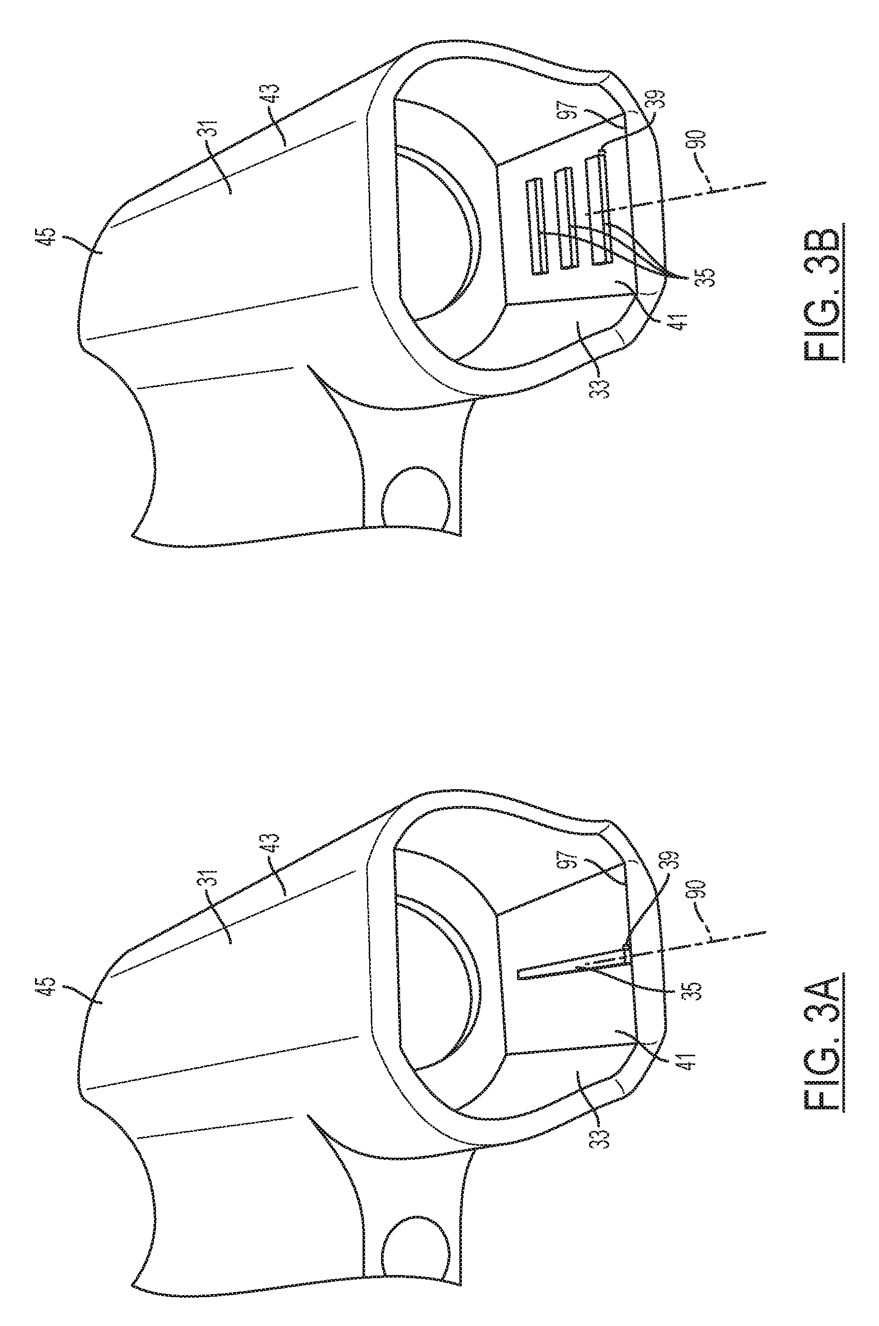
[0023] FIG. 3A is a bottom view of an example, non-limiting anti-rotation member according to the present disclosure
[0024] FIG. 3B is a bottom view of another example, non-limiting anti-rotation member according to the present disclosure
[0025] FIG. 4 is a perspective view of an example, non-limiting cam follower assembly according to various embodiments of the present disclosure.
[0026] Like reference numerals refer to like parts throughout the description of several views of the drawings.
DETAILED DESCRIPTION
[0027] Reference will now be made in detail to presently preferred compositions, embodiments and methods of the present disclosure, which constitute the best modes of practicing the present disclosure presently known to the inventors. The figures are not necessarily to scale. However, it is to be understood that the disclosed embodiments are merely exemplary of the present disclosure that may be embodied in various and alternative forms. Therefore, specific details disclosed herein are not to be interpreted as limiting, but merely as a representative basis for any aspect of the present disclosure and/or as a representative basis for teaching one skilled in the art to variously employ the present disclosure.
[0028] Except in the examples, or where otherwise expressly indicated, all numerical quantities in this description indicating amounts of material or conditions of reaction and/or use are to be understood as modified by the word "about" in describing the broadest scope of the present disclosure. Practice within the numerical limits stated is generally preferred. Also, unless expressly stated to the contrary: percent, "parts of," and ratio values are by weight; the description of a group or class of materials as suitable or preferred for a given purpose in connection with the present disclosure implies that mixtures of any two or more of the members of the group or class are equally suitable or preferred; the first definition of an acronym or other abbreviation applies to all subsequent uses herein of the same abbreviation and applies mutatis mutandis to normal grammatical variations of the initially defined abbreviation; and, unless expressly stated to the contrary, measurement of a property is determined by the same technique as previously or later referenced for the same property.
[0029] It s also to be understood that this present disclosure is not limited to the specific embodiments and methods described below, as specific components and/or conditions may, of course, vary. Furthermore, the terminology used herein is used only for the purpose of describing particular embodiments of the present disclosure and is not intended to be limiting in any way.
[0030] It must also be noted that, as used in the specification and the appended claims, the singular form "a," "an," and "the" comprise plural referents unless the context clearly indicates otherwise. For example, reference to a component in the singular is intended to comprise a plurality of components.
[0031] The term "comprising" is synonymous with "including," "having," "containing," or "characterized by." These terms are inclusive and open-ended and do not exclude additional, un-recited elements or method steps.
[0032] The phrase "consisting of" excludes any element, step, or ingredient not specified in the claim. When this phrase appears in a clause of the lifter body 14 of a claim, rather than immediately following the preamble, it limits only the element set forth in that clause; other elements are not excluded from the claim as a whole.
[0033] The phrase "consisting essentially of" limits the scope of a claim to the specified materials or steps, plus those that do not materially affect the basic and novel characteristic(s) of the claimed subject matter.
[0034] The terms "comprising", "consisting of", and "consisting essentially of" can be alternatively used. Where one of these three terms is used, the presently disclosed and claimed subject matter can include the use of either of the other two terms.
[0035] Throughout this application, where publications are referenced, the disclosures of these publications in their entireties are hereby incorporated by reference into this application to more fully describe the state of the art to which this present disclosure pertains.
[0036] The following detailed description is merely exemplary in nature and is not intended to limit the present disclosure or the application and uses of the present disclosure. Furthermore, there is no intention to be bound by any theory presented in the preceding background or the following detailed description.
[0037] The present disclosure provides an improved cam follower assembly 10 for a vehicle engine 54 which enables increased lost motion range of the roller thereby reducing the risk of cam spalling. With reference to FIG. 1, a cross sectional view of the cam follower assembly 10 of the present invention is shown. The cam follower assembly 10 is disposed within an engine block 12 and operable to enable the valve 48 to open and close against a combustion chamber 50 via the rocker arm 28 and push-rods 22.
[0038] Referring again to FIG. 1, the cam follower assembly 10 is part of a cam 60 in head 56 arrangement in an internal combustion engine 54. A cam 60 of a camshaft is rotatably mounted within the head 56 of the engine 54 as is commonly known in the art. A valve 48 having a valve stem 52 extends from cylinder head 56 toward the rocker arm 28 as is also commonly known in the art. A coiled spring (not shown) biases the valve 48 stem 52 upward in the closed position. The rocker arm 28 is pivotally mounted within the head 56 of the engine as is also commonly known in the art. A first end 30 of the rocker arm 28 engages a top portion of the valve 48 stem 52. A lash adjuster is also provided to adjust valve 48 clearance. In the embodiment shown in FIG. 1, cam follower assembly 10 is mounted within a bore of the head 56 of the engine 54 between the cam 60 and a second end 20 of the rocker arm 28. As the cam 60 rotates the cam follower assembly 10 is forced upwards to engage the second end 20 of the rocker arm 28 causing the rocker arm 28 to pivot and displace the first end 30 of the rocker arm 28 downward to open the valve 48. The hydraulic cam follower assembly 10 may be disposed between the cam 60 and rocker arm 28 to provide zero lash adjustment. The basic arrangement for the position of the valve 48, combustion chamber 50 and cam shaft 124 is generally known in the art. The present invention is directed to the improved structure of the cam follower assembly 10 to support reduced cam spalling while meeting packaging requirements in such a layout.
[0039] Pitting is generally known as a surface fatigue phenomenon which occurs in the concentrated rolling and sliding contact area on the cam lobe 60 in the region where the roller 64 makes contact. Due to the high stresses between the two members as the contact area for the cam lobe 60 surface geometry changes against the roller 64, particles may break out of affected areas, leaving cam lobe 60 surfaces pockmarked with scattered holes. As the pitting progresses to a macro level, a cam lobe spalling condition may occur where the pits on the cam lobe 60 surface coalesce and form irregular craters, cavities and cracks. Cam lobe spalling may occur at 60 degrees from the top of the nose whereas sliding wear may be concentrated at the top of the nose of the cam lobe 60. The large particles that pits produce may be caught in the oil filter or settle at the bottom of the sump. Moreover, when cam lobe spalling occurs, this condition may present operational issues for the combustion chamber 50. Therefore, in order to significantly reduce the cam lobe spalling issue, a cam lobe follower assembly 10 is provided in the present disclosure which allows for an increased range of motion thereby, when combined with a rocker arm with reduced "cam lift to valve lift" ratio, relieving the excessively high concentration of stresses between the roller 64 and the cam lobe 60.
[0040] With reference again to FIG. 1, FIG. 2A thru 2D the cam follower assembly 10 of the present invention includes a lifter body 14 and a tower 26 positioned within a first open end of the lifter body bore 92. Preferably the lifter body 14 and the tower 26 associated with the lifter body 14 are seated in a portion of the head 56 of the engine 54 conventionally suited for hydraulic cam followers. The upper or first open end 18 of the cam follower assembly 10 is adapted to engage the second end 20 of the rocker arm 28 via a pushrod 22. As shown, the pushrod 22 is disposed within a bore 24 of the tower 26 such that the tower 26 and lifter body 14 engage the second end 20 of the rocker arm 28. A primary spring 32 is disposed in spring recess 34 defined by an upper flange 36 of the tower 26, the tower side wall 40, and the spring seat 38. It is further understood that an anti-rotation member 80 may surround this the primary spring 32 and the first open end 18 of the cam follower assembly 10. The primary spring 32 is operatively configured to bias the pushrod 22 and its associated combustion chamber 50 valve 48 into an extended position. A locking member 46 may be further provided to lock the pushrod 22 in the extended position (FIG. 2C) for normal activated operation of the cam follower assembly 10. During normal operation, where the valve 48 (FIG. 1) and locking member 46 (FIG. 3A) is activated as shown in FIG. 3A, the cam 60 causes the cam follower assembly 10 together with the pushrod 22 to move up and down in a reciprocating manner to engage the rocker arm 28 and reciprocatingly operate the valve 48. FIG. 1 shows the cam follower assembly 10 and valve 48 in a closed position.
[0041] However, when the valve 48 (FIG. 1) and locking member 46 (FIGS. 2C and 2D) are not activated, the locking member 46 is stowed in a retracted position (as shown in FIG. 2D) enabling roller 64 and the lifter body 14 to slide up the longitudinal axis 90 toward the tower 26, pin housing 62 and the lifter body 14 as the cam lobe 60 geometry changes as the camshaft rotates. That is, the force exerted by the cam lobe 60 against the roller 64 overcomes the biasing force provided by the primary spring 32 when the locking member 46 is deactivated as shown in FIG. 2D such that the roller 64 and lifter body housing 14 may slide upward relative to the pin housing 62 and tower 26. Accordingly, the position of the pushrod 22 is not affected, and therefore, the combustion chamber valve 48 is not actuated despite the cam lobe 60 engaging the roller 64.
[0042] With further reference to the roller 64 in FIGS. 2A-2D, a roller 64 may be rotatably mounted to a second end 88 of the lifter body 14 of the cam follower assembly 10 and engages a portion of the cam lobe 60 to provide a rolling interface there between. However, as indicated, as the cam 60 rotates the cam follower assembly 10 and pushrod 22 are forced upward and the rocker arm 28 pivots and the valve 48 opens when the locking member 46 is actuated given that the cam follower does not "absorb" the movement/force applied by the cam lobe 60. Therefore, when the locking member 46 is actuated, the entire cam follower assembly 10 together with the pushrod 22 is urged in the upward most position as the roller 64 engages the highest portion of the cam 60. Consequently, the rocker arm 28 pivots clockwise and the valve stem 52 is forced downward to open the valve 48. As the cam lobe 60 continues to rotate, the valve 48 is then allowed to close by virtue of the biasing force of the spring (not shown) in the cylinder head.
[0043] However, when the valve 48 is to be deactivated, the locking member 46 disengages with the inner surface of the lifter body 14, as shown in FIG. 2D, to allow the pushrod 22 to recede within the bore 24 of the tower 26 and lifter body 14 to take up the cam 60 lift so that the valve 48 is not opened. As can be seen in FIG. 2D, the roller 64 may engage the cam 60 (not shown) at its highest point which causes upward movement of the roller 64 in comparison to FIG. 3C. However, the rocker arm 28 and valve 48 of FIG. 1 shall remain in the closed position when the locking member 46 of the lifter body 14 is deactivated. It is understood that, in this example, pressurized oil may be selectively supplied to the locking member 46 to disengage the locking member 46 from the lifter body 14 thereby releasing the pushrod 22/pin housing 62/tower subsystem 52 relative to the lifter body 14 and thus permitting the pushrod 22 to move deeper within the bore of the lifter body 14. As the cam 60 urges the lifter body 14 upward, the pushrod 22 remains substantially stationary relative to the cylinder head 56. Accordingly, when the locking member 46 is disengaged (or deactivated), the lifter body 14 and roller 64 rides upward relative to the tower 26 and pin housing 62 such that the pushrod 22 recesses further within the bore 24 when the highest point of the cam lobe 60 engages with the roller or rolling member 64. The spring biases the pushrod 22 upward relative to the lifter body 14 to engage the second end 20 of the rocker arm 28. Similarly, a primary spring 32 urges the lifter body 14 and roller 64 downward to maintain constant contact with the cam 60.
[0044] Due to issues with respect to cam spalling at the roller 64 interface, the cam follower assembly 10 must be properly aligned at the roller 64-cam 60 interface. FIG. 2A is a front view of a prior art cam follower. FIG. 2B is a rear view of a prior art cam follower 10 where the anti-rotation member 80 is shown in phantom. It is understood that the upon assembly and in operation, the anti-rotation member 80 engages only with the platform 47 (FIG. 2B) defined on the rear side of the lifter body 14 when assembled as part of a traditional cam follower assembly 10. It is desirable to require a certain insertion force to install the cam follower into the anti-rotation member 80 so that the cam follower stays in its proper position (rotationally and linearly) when the sub-assembly of the anti-rotation member 80 and lifter body 14 are put together and when the sub-assembly is mated to the engine.
[0045] As previously noted, plastic guide shears in a traditional anti-rotation member (not shown) are defined on the inner surface of a traditional anti-rotation member which engage with a platform defined on the lifter body (not shown) of a traditional cam follower assembly (not shown). However, despite this interface, cam followers have been known to fall out of the anti-rotation members during the subassembly process and the assembly process of mating the subassembly to the engine. As a result, there is a risk for the roller of the cam follower to be misaligned with the cam when the cam follower is re-inserted into a traditional anti-rotation member.
[0046] With reference to FIGS. 3A-3B and 4, an improved cam follower assembly 10 is provided. The improved cam follower includes a lifter body 14, a spring seat 38, a tower 26, a spring 32 and an anti-rotation member 80 having one or more interference ribs 35. It is understood that the interference rib(s) 35 or dimple(s) 35 may come in various shapes. Regardless, the interference rib 35 or dimple 35 may be any raised feature which may deform or disintegrate as described. The anti-rotation member 80 of the present disclosure may further include an upper end 45 and a lower end 43, and my further includes an outer surface 31 and an inner surface 33 with one or more interference ribs integral to the inner surface 33. The one or more interference ribs may be defined on an inner surface 33 of the anti-rotation member 80 proximate to the lower end 43. The interference rib 35 is configured to abut an upper region 51 (FIGS. 2A-2B) of a lifter body 14 when the lifter body 14 is inserted inside of the anti-rotation member 80. It is also understood that the interference rib(s) 35 may deform upon insertion of the lifter body 14 within the anti-rotation member 80, or the interference rib(s) 35 may deform when the engine is operating and the lifter body 14 reciprocates relative to the camshaft.
[0047] Referring again to FIGS. 3A-3B, the interference rib(s) 35 may protrude from the inner surface 33 of the anti-rotation member 80 by a distance/depth 39 (FIGS. 3A-3B) which falls in the range of about 1 mm to about 5 mm (and/or a width 37 shown in FIGS. 2A and 2B which falls in the range of about 1 mm to about 5 mm) wherein the interference rib 35 may be integral to the anti-rotation member 80 via an injection molding process, or in yet another non-limiting, optional arrangement, the interference rib 35 is integral to the anti-rotation member 80 via an over-molding process. While each anti-rotation member 80 may include as few as one interference rib 35. an anti-rotation member 80 of the present disclosure may, but not necessarily include a plurality of interference ribs 35 in various regions of the inner surface 33. The inner surface 33 of the anti-rotation member 80 may vary such that the inner surface 33 includes at least one flat region and at least one curved region 39. Regardless, the interference rib 35 of the present disclosure may be integral to either a flat region or a curved region 39 of the inner surface 33.
[0048] With reference now to 2C and 2D, an example, non-limiting lifter body 14 is shown which may be implemented as part of the cam follower assembly 10 of the present disclosure. The lifter body 14 may be disposed along the longitudinal axis 90 wherein the lifter body 14 includes a first open end 44, and a second end 88. The lifter body 14 may engage with a cam via a rolling member 64 affixed to the second end 88. A spring seat 38 may be disposed at the first open end of the lifter body 14 wherein the spring seat 38 defines a spring seat opening 84 which supports the tower 26. As shown in the non-limiting example of FIGS. 2C and 2D, an example, non-limiting tower 26 may be implemented to couple a pushrod to the lifter body 14. The tower 26 may also include an upper flange 36 such that a spring may be disposed between the spring seat 38 and the upper flange 36 of the tower 26. As shown in FIGS. 2C-2D, the tower 26 may, but not necessarily, be disposed in a pin housing 62 through the spring seat opening 84 at the first open end of the lifter body 14. The pin housing 62 is disposed within the lifter body 14 such that the pin housing 62, the tower 26, the lifter body 14 and the aperture of the anti-rotation member 80 are aligned with the longitudinal axis 90.
[0049] As shown in FIG. 4, lifter body 14 may be inserted into the lower end 43 of the anti-rotation member 80 such that the first open end of the lifter body 14 engages with the lower end 43 of the anti-rotation member 80 with the interference ribs abutting the lifter body 14. wherein. As shown, the interference rib(s) 35 are configured to engage with an upper region of the lifter body 14 so as to prevent the lifter body 14 from falling out of the anti-rotation member 80 during the assembly process. Moreover, the interference ribs are configured to prevent the lifter body 14 from rotating out of position within the anti-rotation member 80. As indicated earlier, the roller (rolling member 64) of the lifter body 14 needs to be properly aligned with the roller's associated cam in order to prevent premature damage/failure at the cam. Again, it is understood that "proper alignment" between the rolling member 64 and the cam 60 should be construed to mean that the each of the rolling member 64 and the cam 60 are centered and aligned with longitudinal axis 90. See FIG. 2A.
[0050] Referring now to FIGS. 3A and 4, an example, non-limiting improved cam follower assembly 10 of the present disclosure may include one or more interference ribs which are substantially parallel to the longitudinal axis 90. Alternatively, with reference to FIG. 3B, another example, non-limiting improved cam follower of the present disclosure may include one or more interference ribs which are substantially perpendicular to the longitudinal axis 90. While not shown, the interference rib of the present disclosure may also be disposed at an angle relative to the longitudinal axis 90 of each lifter/guide aperture.
[0051] Referring now to FIGS. 3A and 3B, an example, non-limiting cam follower may include a planar surface 41 (or flat region 41) which is defined on the interior surface of the anti-rotation member 80 proximate to a lower end 43 of the anti-rotation member 80. As shown, the interference rib 35 may be defined on the planar surface 41 such that the interference rib 35 may be over-molded onto the planar surface 41 or the interference rib 35 may injection molded as the planar surface 41 and the remainder of the anti-rotation member 80 is injection molded. The anti-rotation member 80 and the interference rib(s) 35 may, but not necessarily, be formed from material such as Nylon 66 with 32% glass, or other like material. In the event the interference rib 35 is overmolded onto the anti-rotation member 80, the interference rib 35 may be formed from another polymeric material which may or may not have a higher modulus of elasticity. In yet another non-limiting option, the interference rib 35 may be formed from a wax like material which is molded onto the inner surface 33.
[0052] When the interference rib(s) 35 is/are formed on a planar surface 41 (or flat region 41) of the anti-rotation member 80, it is understood that the lifter body 14 may define a compatible planar surface 47 (as shown in FIG. 2B) which is configured to engage with and mate with the planar surface 41 of the anti-rotation member 80. Alternatively, the interference rib(s) 35 may be formed on a curved surface 39 (or curved region 39) of the anti-rotation member 80 as shown in FIG. 2B. Regardless of whether the interference rib(s) 35 is/are formed on a flat region 41 or a curved region 39, the interference rib(s) 35 are configured to prevent the lifter body 14 from falling out of the anti-rotation member's opening 97 during the assembly process and also to prevent the lifter body 14 from rotating out of position within the anti-rotation member's opening 97--so that the roller member is properly aligned with the roller member's associated cam 60. Regardless of whether the interference rib(s) 35 are defined on a curved region or on a flat region 41 of the anti-rotation member 80, the interference rib(s) 35 may deform upon initial insertion of the lifter body 14 into the anti-rotation member's opening 97. Alternatively, the interference rib(s) 35 may deform upon actuation of lifter body 14 and roller onto the cam 60 during an initial operation of the vehicle engine.
[0053] In yet another embodiment of the present disclosure, an anti-rotation member 80 may include an outer surface 31, an inner surface 33 and an interference rib 35 integral to the inner surface 33. The interference rib 35 may be configured to deform and retain a first open end 44 of a lifter body 14 when the first open end 44 of the lifter body 14 engages with the interference rib 35. In one non-limiting example arrangement, the interference rib(s) 35 may be over-molded onto the inner surface 33. In yet another non-limiting example arrangement, the interference rib(s) 35 may be injection molded simultaneously with the inner surface 33 and the outer surface 31.
[0054] With reference to FIGS. 3A-3D, the improved cam follower 10 includes a lifter body 14. The lifter body 14 may come in various forms. However, in the example of FIGS. 2C-2D, the lifter body 14 may include a spring seat 38 and a primary spring 32 made from steel. The example primary spring 32 of FIGS. 2A-2D may have a specified spring constant.
[0055] FIG. 3A is a front view of an example, non-limiting cam follower assembly 10 of the present disclosure where the anti-rotation member 80 shown in phantom while FIG. 3B is a rear view of the cam follower assembly 10 in FIG. 3A. As shown, the lifter body 14 defines a first open end 44, and a second end 88. The spring seat 38 may define a spring seat opening 84. The spring seat 38 may be affixed to the first open end 44 of the lifter body 14. The tower 26 may be disposed in a pin housing 62 through the spring seat opening 84 at the first open end 44 of the lifter body 14. The tower 26 further includes an upper flange 36 and a spring which abuts the upper flange 36 at a first spring end 78. The second spring end 76 abuts the spring seat 38. The anti-rotation member 80 accordingly may be coupled to the lifter body 14 via the spring seat 38.
[0056] With reference to the non-limiting example lifter body 14 of FIGS. 2C-2D, the pin housing 62 may support the push rod seat 63 within the lifter body 14, and the lifter body 14 be fixed relative to the tower 26. However, as shown in FIGS. 2C-2D, the lifter body 14 moves relative to the pin housing 62 and tower 26. As shown, the pin housing 62 may be affixed to a second end 86 of the tower 26. The pin housing 62 may also be disposed entirely within the lifter body 14 such that the pin housing 62 may slide relative to the lifter body 14 depending on whether the locking member 46 is engaged (as shown in FIG. 2C) or disengaged (as shown in FIG. 2D). When the locking member 46 is engaged into the locking recesses 47 defined in the interior wall of the lifter body 14, the first open end 61 of the pin housing 62 may be disposed proximate to or adjacent to the first open end 44 of the lifter body 14 as shown in FIG. 2C. However, when the locking member 46 is disengaged from the lifter body 14, the lifter body 14 and roller 64 of the cam follower 10 may slide relative to the pushrod 22 and pin housing 62 which remain stationary.
[0057] With further reference to the non-limiting example lifter body 14 shown in FIGS. 2A-2D, the example primary spring 32 may include a first spring end 78 and a second spring end 76. The first spring end 78 abuts an upper flange 36 of the tower 26 at a first spring end 78 and abuts the spring seat 38 at a second spring end 76 upon assembly. The spring recess 34 is therefore defined by the tower side wall 40, the upper flange 36, and the spring seat 38, and the spring recess 34 is configured to retain the primary spring 32 as described above for the improved cam follower assembly 10. Therefore, the second spring end 76 (shown in FIG. 2A) is supported by the spring seat 38.
[0058] While at least one exemplary embodiment has been presented in the foregoing detailed description, it should be appreciated that a vast number of variations exist. It should also be appreciated that the exemplary embodiment or exemplary embodiments are only examples, and are not intended to limit the scope, applicability, or configuration of the disclosure in any way. Rather, the foregoing detailed description will provide those skilled in the art with a convenient road map for implementing the exemplary embodiment or exemplary embodiments. It should be understood that various changes can be made in the function and arrangement of elements without departing from the scope of the disclosure as set forth in the appended claims and the legal equivalents thereof.
* * * * *
D00000
D00001
D00002
D00003
D00004
D00005
XML
uspto.report is an independent third-party trademark research tool that is not affiliated, endorsed, or sponsored by the United States Patent and Trademark Office (USPTO) or any other governmental organization. The information provided by uspto.report is based on publicly available data at the time of writing and is intended for informational purposes only.
While we strive to provide accurate and up-to-date information, we do not guarantee the accuracy, completeness, reliability, or suitability of the information displayed on this site. The use of this site is at your own risk. Any reliance you place on such information is therefore strictly at your own risk.
All official trademark data, including owner information, should be verified by visiting the official USPTO website at www.uspto.gov. This site is not intended to replace professional legal advice and should not be used as a substitute for consulting with a legal professional who is knowledgeable about trademark law.